Page 2689 of 5267

TRANSMISSION ADAPTER
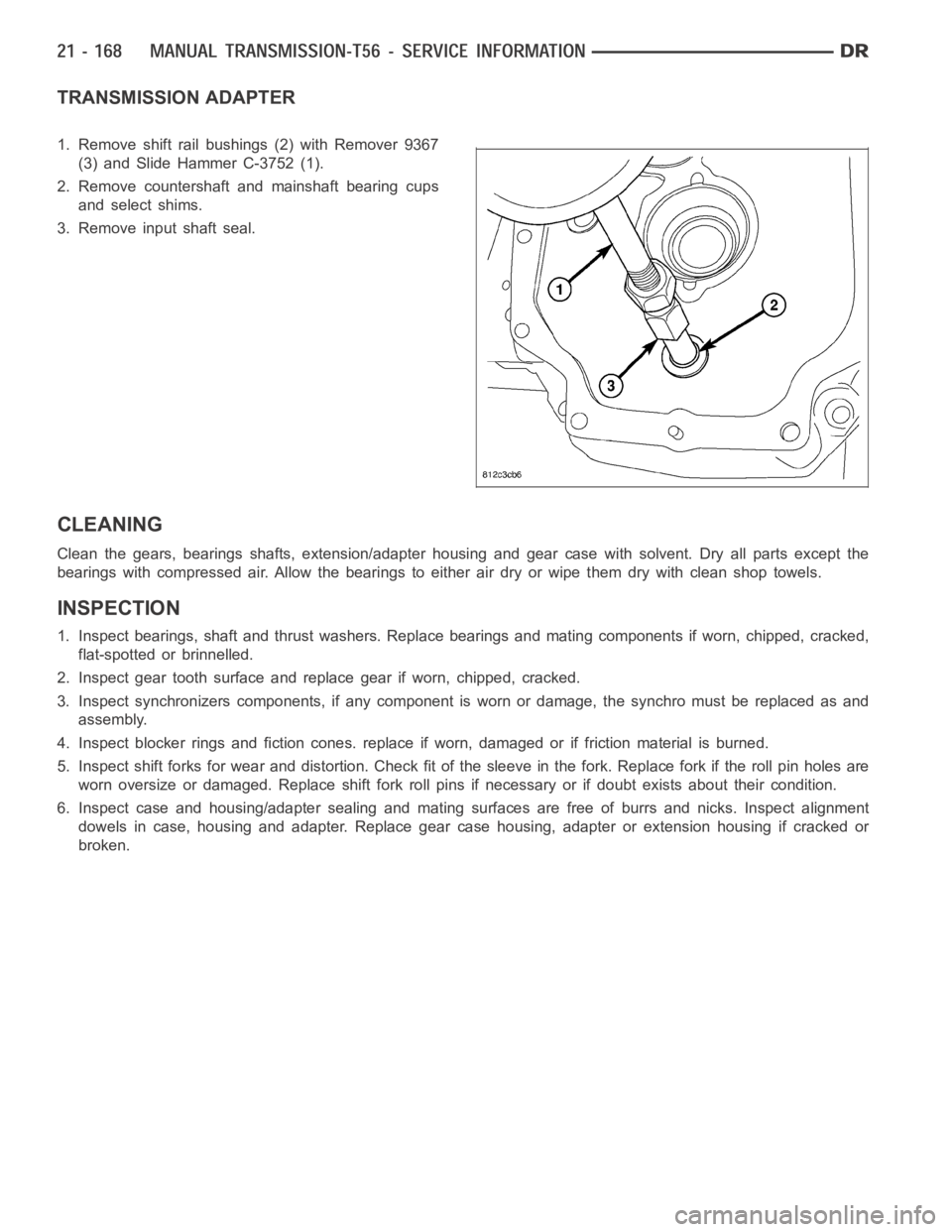
1. Remove shift rail bushings (2) with Remover 9367
(3) and Slide Hammer C-3752 (1).
2. Remove countershaft and mainshaft bearing cups
and select shims.
3. Remove input shaft seal.
CLEANING
Clean the gears, bearings shafts, extension/adapter housing and gear case with solvent. Dry all parts except the
bearings with compressed air. Allow the bearings to either air dry or wipe them dry with clean shop towels.
INSPECTION
1. Inspect bearings, shaft and thrust washers. Replace bearings and mating components if worn, chipped, cracked,
flat-spotted or brinnelled.
2. Inspect gear tooth surface and replace gear if worn, chipped, cracked.
3. Inspect synchronizers components, if any component is worn or damage, the synchro must be replaced as and
assembly.
4. Inspect blocker rings and fiction cones. replace if worn, damaged or if friction material is burned.
5. Inspect shift forks for wear and distortion. Check fit of the sleeve in the fork. Replace fork if the roll pin holes are
worn oversize or damaged. Replace shift fork roll pins if necessary or if doubt exists about their condition.
6. Inspect case and housing/adapter sealing and mating surfaces are free of burrs and nicks. Inspect alignment
dowels in case, housing and adapter. Replace gear case housing, adapter orextension housing if cracked or
broken.
Page 2698 of 5267
7. Install 1-2 thrust washer and blocker ring (1)
assembly onto 1-2 synchronizer (2).
8. Installoriginalornew1-2 synchronizer (1) snap
ring (2) on mainshaft.
9. Install first gear (1) and bearing (2) on mainshaft.
Page 2703 of 5267
12. Apply Loctite242 to shift detente (1) threads.
Install shift detente assembly withnewO-ring and
tighten to 34 Nꞏm (25 ft. lbs.).
13. Install reverse lock-out solenoid.
14. Apply Mopar
Gasket Maker to top plate sealing
surface.
15. Install top plate bolts and tighten to 20 Nꞏm (15 ft.
lbs.).
16. Install sixth gear bearing and gear (1) on counter-
shaft (2).
.
17. Install sixth gear stop ring (1).
Page 2708 of 5267
32. Install reverse gear (3), bearing (5), wave washer
(2) and brass blocker ring (1) on mainshaft (4).
33. Install reverse gear (1) thrust washer (2) and snap
ring (4).
.
34. Install mainshaft (3) roller bearing (4), spacers (2)
and snap ring.
35. Apply Mopar
Gasket Maker to tail housing seal-
ing surface.
Page 2711 of 5267
6. Install back up lamp switch (2) connector (1).
7. Install fuel line to top plate stud.
8. Install reverse lockout solenoid (1) harness connec-
tor (2).
9. Install hydraulic clutch quick connector (1) to the
slave cylinder.
10. Clean transmission shifter tower sealing surfaces
and apply a bead of Mopar
Gasket Maker.
11. Install shifter tower and tighten bolts to 18 Nꞏm
(156 in. lbs.).
12. Install propeller shaft with reference marks
aligned.
CAUTION: The drive shaft strap bolts must be
replaced or cleaned and Loctite
242 applied.
CAUTION: Replace drive shaft joint straps when-
ever they are removed. The straps slightly deform
when torqued in place. Reuse of the straps may
result in reduced clamp load on the universal joint
cap.
Page 2713 of 5267

COUNTERSHAFT BEARINGS PRELOAD
1. Install countershaft with original shim into adapter.
2. Install case and bolt together using all bolts.
3. Rotate countershaft to seat bearings.
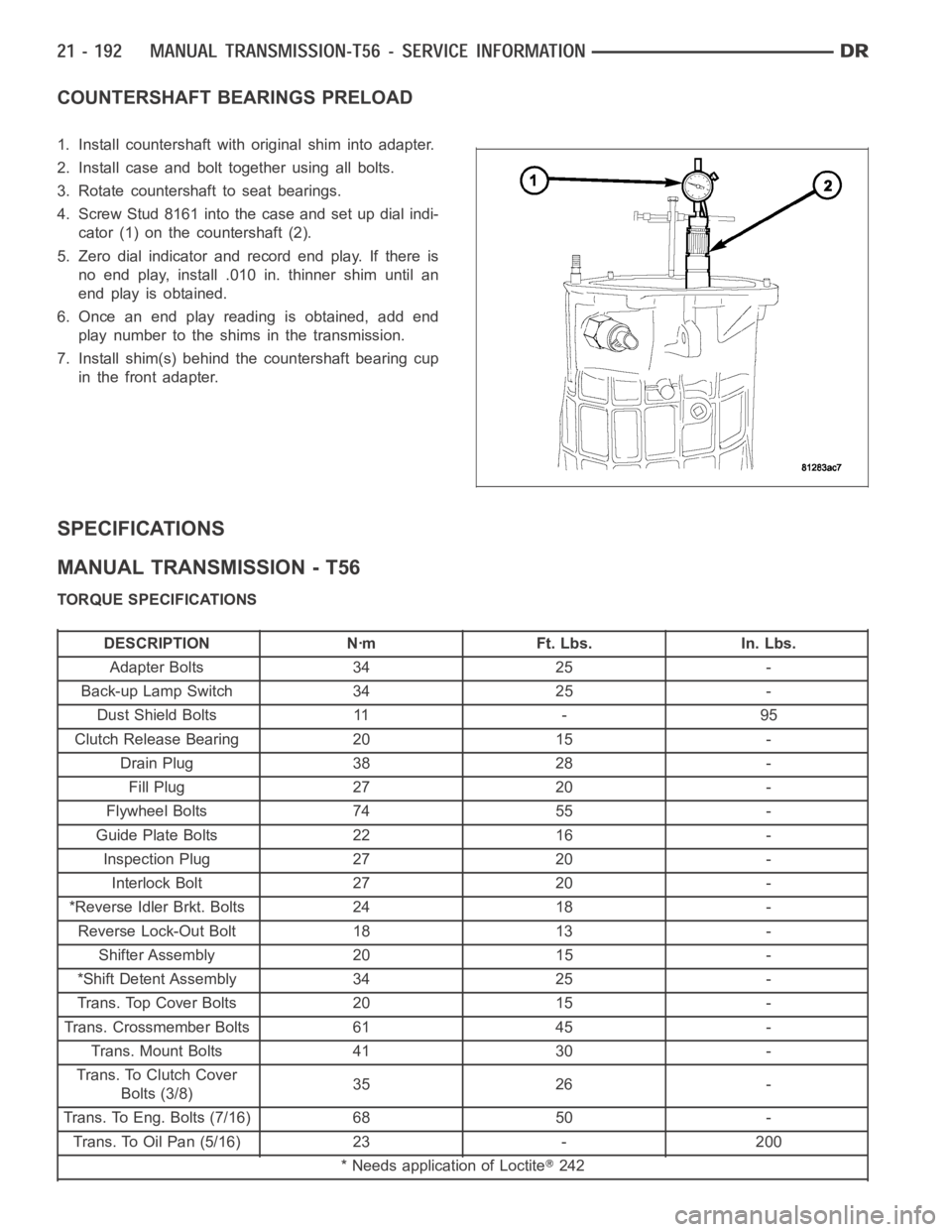
4. Screw Stud 8161 into the case and set up dial indi-
cator (1) on the countershaft (2).
5. Zero dial indicator and record end play. If there is
no end play, install .010 in. thinner shim until an
end play is obtained.
6. Once an end play reading is obtained, add end
play number to the shims in the transmission.
7. Install shim(s) behind the countershaft bearing cup
in the front adapter.
SPECIFICATIONS
MANUAL TRANSMISSION - T56
TORQUE SPECIFICATIONS
DESCRIPTION Nꞏm Ft. Lbs. In. Lbs.
Adapter Bolts 34 25 -
Back-up Lamp Switch 34 25 -
Dust Shield Bolts 11 - 95
Clutch Release Bearing 20 15 -
Drain Plug 38 28 -
Fill Plug 27 20 -
Flywheel Bolts 74 55 -
Guide Plate Bolts 22 16 -
Inspection Plug 27 20 -
Interlock Bolt 27 20 -
*Reverse Idler Brkt. Bolts 24 18 -
Reverse Lock-Out Bolt 18 13 -
Shifter Assembly 20 15 -
*Shift Detent Assembly 34 25 -
Trans. Top Cover Bolts 20 15 -
Trans. Crossmember Bolts 61 45 -
Trans. Mount Bolts 41 30 -
Trans. To Clutch Cover
Bolts (3/8)35 26 -
Trans. To Eng. Bolts (7/16) 68 50 -
Trans. To Oil Pan (5/16) 23 - 200
* Needs application of Loctite
242
Page 2722 of 5267
SOLENOID-REVERSE LOCKOUT
DESCRIPTION
The reverse lockout solenoid prevents shifting into reverse when the vehicle speed is greater than 5 mph. Solenoid
is threaded into the left side of the transmission.
OPERATION
When vehicle speed is less than 5 mph, the PCM provides a ground for the solenoid (energized) and allows shifting.
When vehicle speed is greater than 5 mph, the solenoid is deactivated and prevents the transmission from being
shifted into reverse.
Page 2723 of 5267
SOLENOID-REVERSE LOCK-OUT
DESCRIPTION
The reverse lockout solenoid prevents the operator from shifting into reverse when the vehicle speed is greater than
5 mph. The solenoid is threaded intothe left side of the transmission.
OPERATION
When vehicle speed is less than 5 mph, the PCM provides a ground for the solenoid (energized) and allows shifting.
When vehicle speed is greater than 5 mph, the solenoid is deactivated and prevents the transmission from being
shifted into reverse.