Page 2131 of 5267
INSPECTION
1. The crankshaft journals should be checked for excessive wear, taper andscoring. Limits of taper or out-of-round
on any crankshaft journals should be held to 0.025 mm (0.001 in.). Journal grinding should not exceed 0.508 mm
(0.020 inch) under the standard journal diameter. DO NOT grind thrust faces of No. 3 main bearing. DO NOT
nick crank pin or bearing fillets. After grinding, remove rough edges fromcrankshaft oil holes and clean out all
passages.
CAUTION: With the forged crankshafts it is important that the final paper or cloth polish after any journal
regrind be in the same direction as normal rotation in the engine.
2. Check and clean all oil holes for blockage and debris.
INSTALLATION
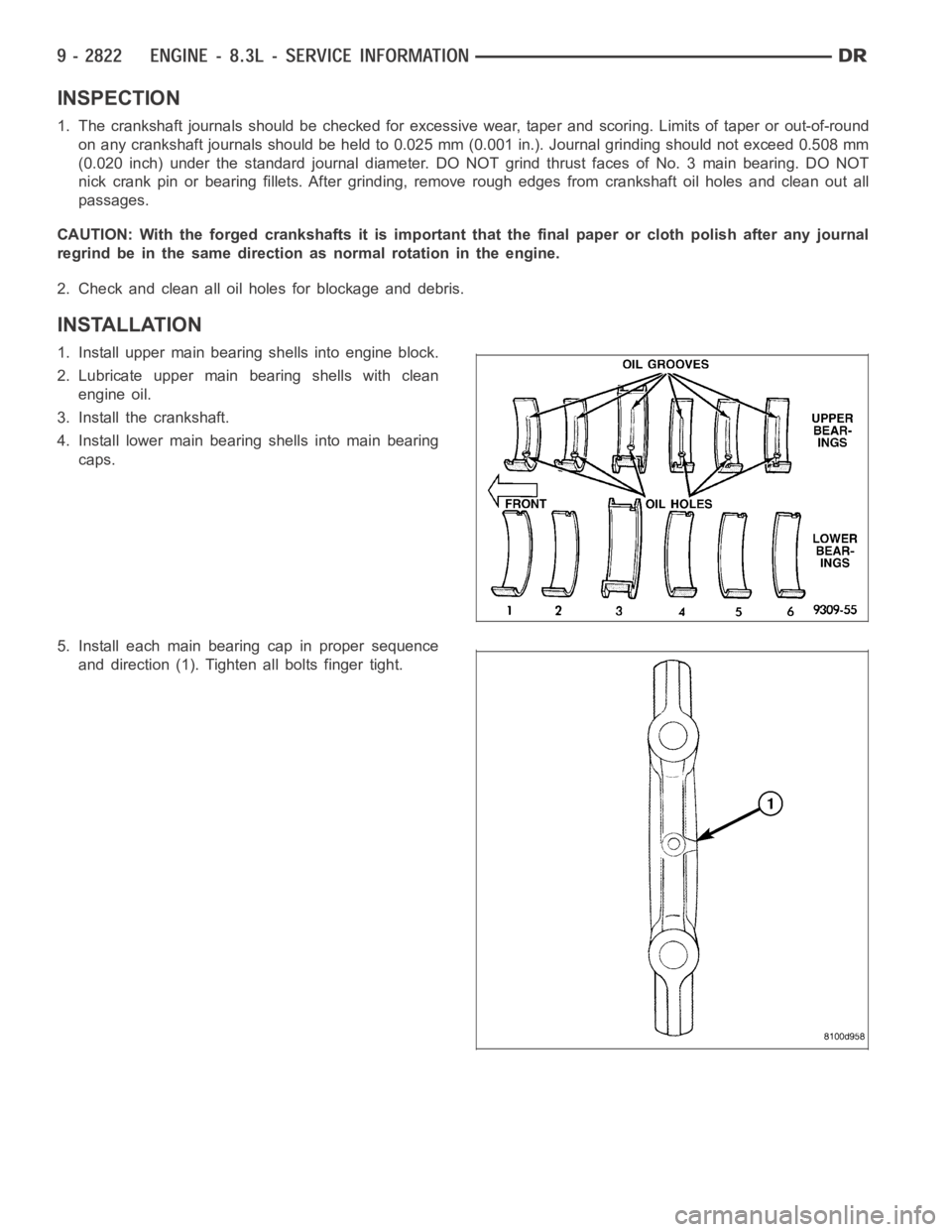
1. Install upper main bearing shells into engine block.
2. Lubricate upper main bearing shells with clean
engine oil.
3. Install the crankshaft.
4. Install lower main bearing shells into main bearing
caps.
5. Install each main bearing cap in proper sequence
and direction (1). Tighten all bolts finger tight.
Page 2132 of 5267
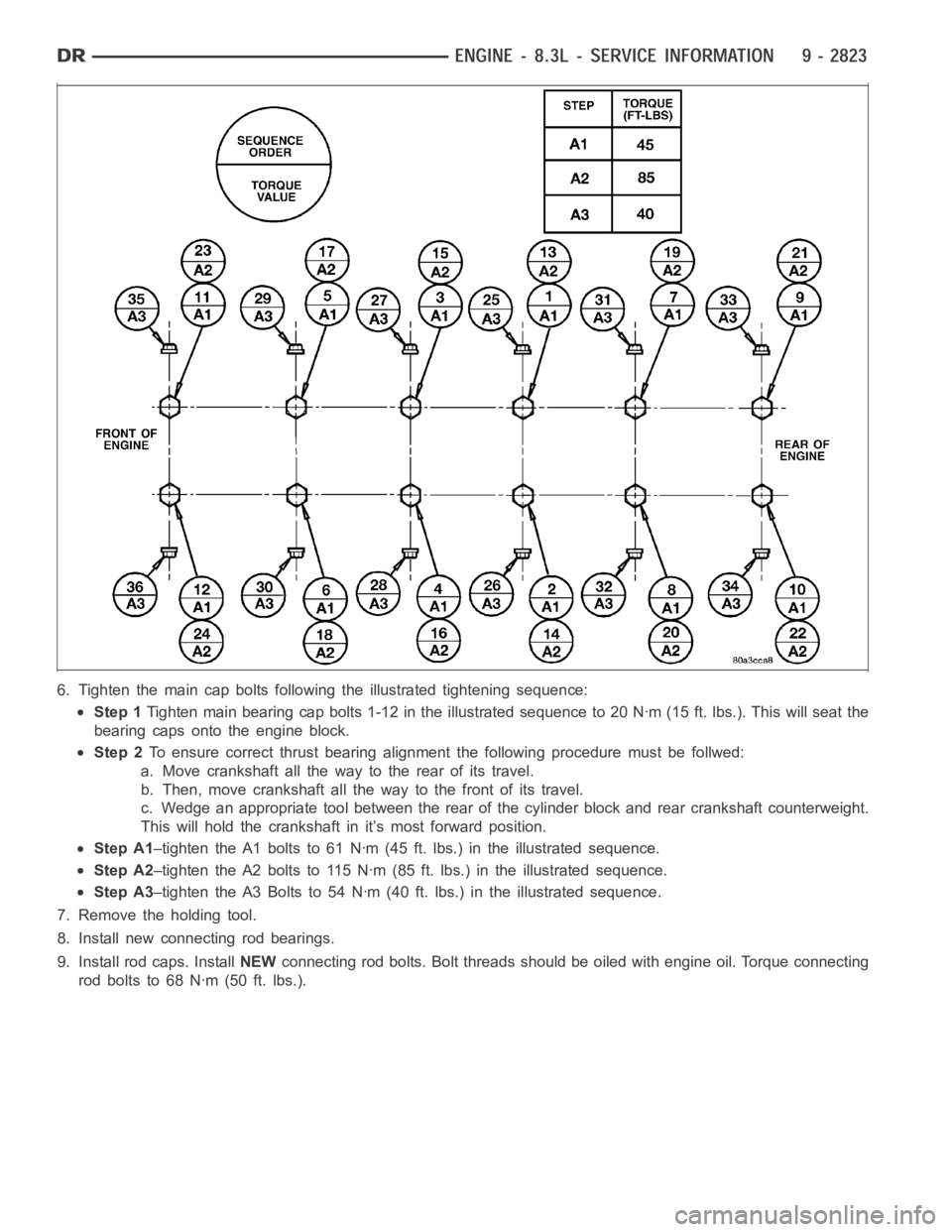
6. Tighten the main cap bolts following the illustrated tightening sequence:
Step 1Tighten main bearing cap bolts 1-12 inthe illustrated sequence to 20 Nꞏm (15 ft. lbs.). This will seat the
bearing caps onto the engine block.
Step 2To ensure correct thrust bearing alignment the following procedure must be follwed:
a. Move crankshaft all the way to the rear of its travel.
b. Then, move crankshaft all the way to the front of its travel.
c. Wedge an appropriate tool between the rear of the cylinder block and rearcrankshaft counterweight.
This will hold the crankshaft in it’s most forward position.
Step A1–tighten the A1 bolts to 61 Nꞏm (45 ft. lbs.) in the illustrated sequence.
Step A2–tighten the A2 bolts to 115 Nꞏm (85 ft. lbs.) in the illustrated sequence.
Step A3–tighten the A3 Bolts to 54 Nꞏm (40 ft. lbs.) in the illustrated sequence.
7. Remove the holding tool.
8. Install new connecting rod bearings.
9. Install rod caps. InstallNEWconnecting rod bolts. Bolt threads should be oiled with engine oil. Torqueconnecting
rod bolts to 68 Nꞏm (50 ft. lbs.).
Page 2133 of 5267
10. Install the crankshaft oil scraper and tighten nuts
to 23 Nꞏm (200 in. lbs.).
11.Installoilpumppickuptube(2)usinganew
o-ring (4). Torque 1/4-20 bolt to 11 Nꞏm (95 in.
lbs.). Torque 5/16-18 nuts to 23 Nꞏm (200 in. lbs.).
12. Install the crankshaft rear oil seal and retainer
(Refer to 9 - ENGINE/ENGINE BLOCK/CRANK-
SHAFT REAR OIL SEAL RETAINER - INSTALLA-
TION).
13. Install lower crankshaft gear along with the timing
chain (Refer to 9 - ENGINE/VALVE TIMING/TIM-
ING CHAIN AND SPROCKETS - INSTALLA-
TION).
14. Install timing chain cover (Refer to 9 - ENGINE/
VALVE TIMING/TIMING CHAIN COVER(S) -
INSTALLATION).
15. Install oil pan (Refer to 9 - ENGINE/LUBRICA-
TION/OIL PAN - INSTALLATION).
16. Install crankshaft damper and pulley (Refer to 9 -
ENGINE/ENGINE BLOCK/VIBRATION DAMPER -
INSTALLATION).
17. Install engine assembly (Refer to 9 - ENGINE -
INSTALLATION).
Page 2140 of 5267
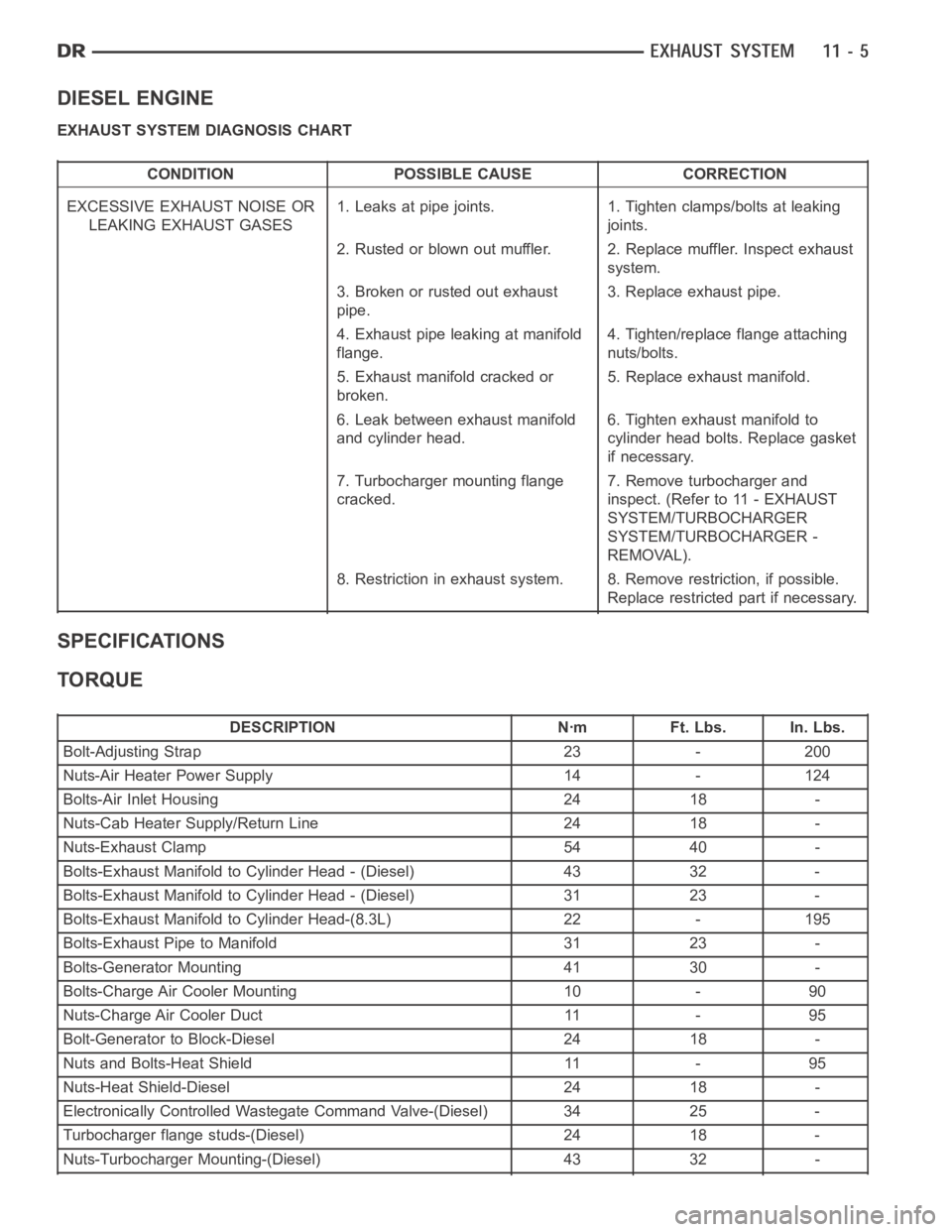
DIESEL ENGINE
EXHAUST SYSTEM DIAGNOSIS CHART
CONDITION POSSIBLE CAUSE CORRECTION
EXCESSIVE EXHAUST NOISE OR
LEAKING EXHAUST GASES1. Leaks at pipe joints. 1. Tighten clamps/bolts at leaking
joints.
2. Rusted or blown out muffler. 2. Replace muffler. Inspect exhaust
system.
3. Broken or rusted out exhaust
pipe.3. Replace exhaust pipe.
4. Exhaust pipe leaking at manifold
flange.4. Tighten/replace flange attaching
nuts/bolts.
5. Exhaust manifold cracked or
broken.5. Replace exhaust manifold.
6. Leak between exhaust manifold
and cylinder head.6. Tighten exhaust manifold to
cylinder head bolts. Replace gasket
if necessary.
7. Turbocharger mounting flange
cracked.7. Remove turbocharger and
inspect. (Refer to 11 - EXHAUST
SYSTEM/TURBOCHARGER
SYSTEM/TURBOCHARGER -
REMOVAL).
8. Restriction in exhaust system. 8. Remove restriction, if possible.
Replace restricted part if necessary.
SPECIFICATIONS
TORQUE
DESCRIPTION Nꞏm Ft. Lbs. In. Lbs.
Bolt-Adjusting Strap 23 - 200
Nuts-Air Heater Power Supply 14 - 124
Bolts-Air Inlet Housing 24 18 -
Nuts-Cab Heater Supply/Return Line 24 18 -
Nuts-Exhaust Clamp 54 40 -
Bolts-Exhaust Manifold to Cylinder Head - (Diesel) 43 32 -
Bolts-Exhaust Manifold to Cylinder Head - (Diesel) 31 23 -
Bolts-Exhaust Manifold to Cylinder Head-(8.3L) 22 - 195
Bolts-Exhaust Pipe to Manifold 31 23 -
Bolts-Generator Mounting 41 30 -
Bolts-Charge Air Cooler Mounting 10 - 90
Nuts-Charge Air Cooler Duct 11 - 95
Bolt-Generator to Block-Diesel 24 18 -
Nuts and Bolts-Heat Shield 11 - 95
Nuts-Heat Shield-Diesel 24 18 -
Electronically Controlled Wastegate Command Valve-(Diesel) 34 25 -
Turbocharger flange studs-(Diesel) 24 18 -
Nuts-Turbocharger Mounting-(Diesel) 43 32 -
Page 2165 of 5267
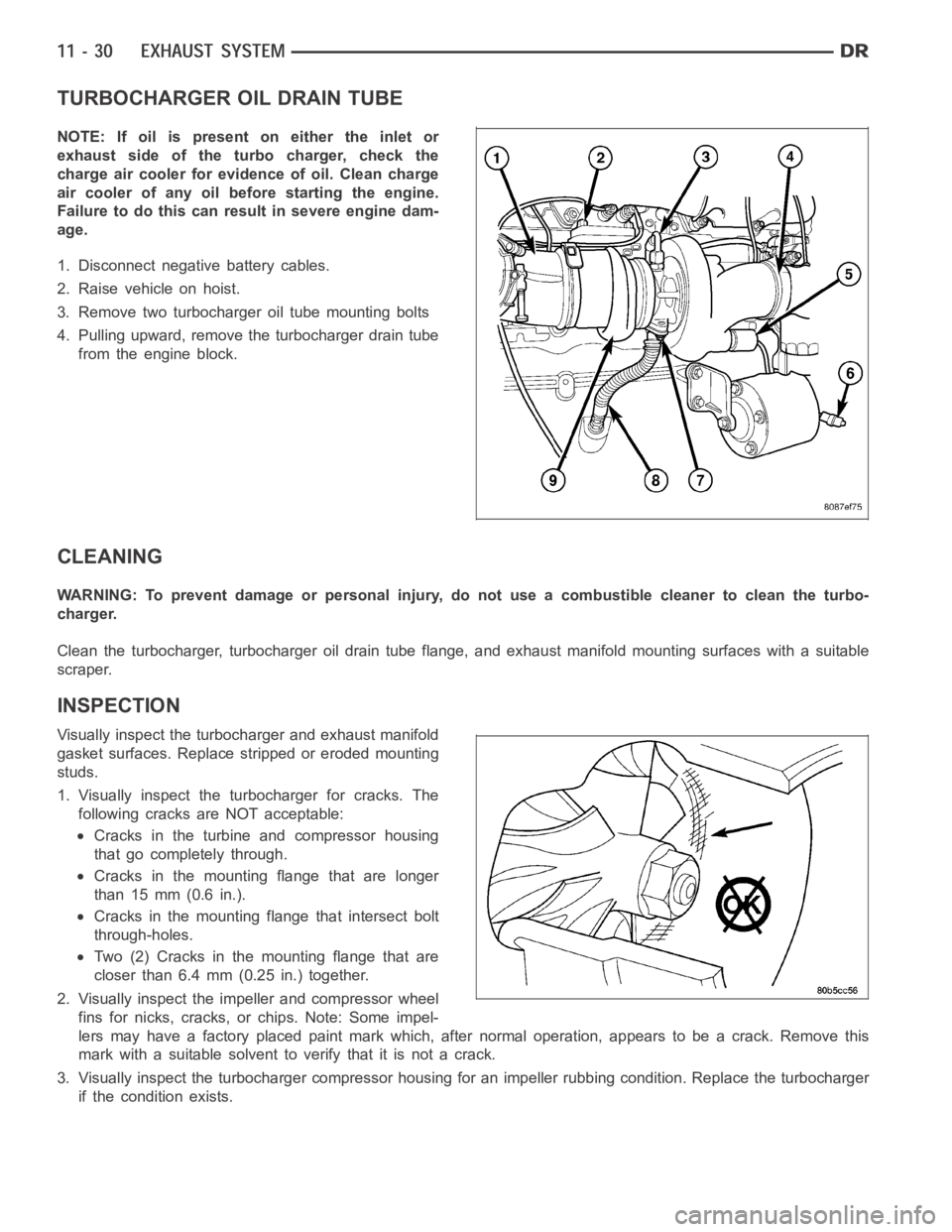
TURBOCHARGER OIL DRAIN TUBE
NOTE: If oil is present on either the inlet or
exhaust side of the turbo charger, check the
charge air cooler for evidence of oil. Clean charge
air cooler of any oil before starting the engine.
Failure to do this can result in severe engine dam-
age.
1. Disconnect negative battery cables.
2. Raise vehicle on hoist.
3. Remove two turbocharger oil tube mounting bolts
4. Pulling upward, remove the turbocharger drain tube
from the engine block.
CLEANING
WARNING: To prevent damage or personal injury, do not use a combustible cleaner to clean the turbo-
charger.
Clean the turbocharger, turbocharger oil drain tube flange, and exhaust manifold mounting surfaces with a suitable
scraper.
INSPECTION
Visually inspect the turbocharger and exhaust manifold
gasket surfaces. Replace stripped or eroded mounting
studs.
1. Visually inspect the turbocharger for cracks. The
following cracks are NOT acceptable:
Cracks in the turbine and compressor housing
that go completely through.
Cracks in the mounting flange that are longer
than 15 mm (0.6 in.).
Cracks in the mounting flange that intersect bolt
through-holes.
Two (2) Cracks in the mounting flange that are
closer than 6.4 mm (0.25 in.) together.
2. Visually inspect the impeller and compressor wheel
fins for nicks, cracks, or chips. Note: Some impel-
lers may have a factory placed paint mark which, after normal operation, appears to be a crack. Remove this
mark with a suitable solvent to verify that it is not a crack.
3. Visually inspect the turbocharger compressor housing for an impeller rubbing condition. Replace the turbocharger
if the condition exists.
Page 2167 of 5267
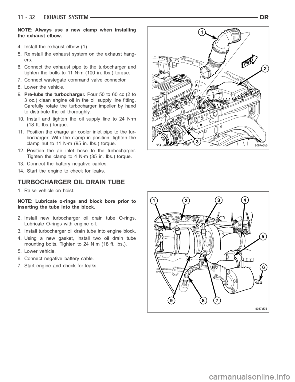
NOTE: Always use a new clamp when installing
the exhaust elbow.
4. Install the exhaust elbow (1)
5. Reinstall the exhaust system on the exhaust hang-
ers.
6. Connect the exhaust pipe to the turbocharger and
tighten the bolts to 11 Nꞏm (100 in. lbs.) torque.
7. Connect wastegate command valve connector.
8. Lower the vehicle.
9.Pre-lube the turbocharger.Pour 50 to 60 cc (2 to
3 oz.) clean engine oil in the oil supply line fitting.
Carefully rotate the turbocharger impeller by hand
to distribute the oil thoroughly.
10. Install and tighten the oil supply line to 24 Nꞏm
(18 ft. lbs.) torque.
11. Position the charge air cooler inlet pipe to the tur-
bocharger. With the clamp in position, tighten the
clamp nut to 11 Nꞏm (95 in. lbs.) torque.
12. Position the air inlet hose to the turbocharger.
Tighten the clamp to 4 Nꞏm (35 in. lbs.) torque.
13. Connect the battery negative cables.
14. Start the engine to check for leaks.
TURBOCHARGER OIL DRAIN TUBE
1. Raise vehicle on hoist.
NOTE: Lubricate o-rings and block bore prior to
inserting the tube into the block.
2. Install new turbocharger oil drain tube O-rings.
Lubricate O-rings with engine oil.
3. Install turbocharger oil drain tube into engine block.
4. Using a new gasket, install two oil drain tube
mounting bolts. Tighten to 24 Nꞏm (18 ft. lbs.).
5. Lower vehicle.
6. Connect negative battery cable.
7. Start engine and check for leaks.
Page 2241 of 5267
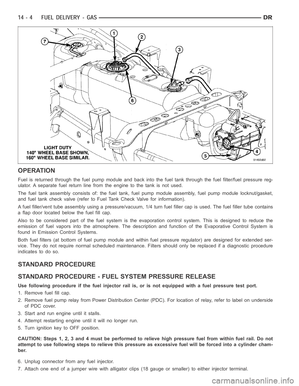
OPERATION
Fuel is returned through the fuel pump module and back into the fuel tank through the fuel filter/fuel pressure reg-
ulator. A separate fuel return line from the engine to the tank is not used.
The fuel tank assembly consists of: the fuel tank, fuel pump module assembly, fuel pump module locknut/gasket,
and fuel tank check valve (refer to Fuel Tank Check Valve for information).
A fuel filler/vent tube assembly using apressure/vacuum,1/4 turn fuel filler cap is used. The fuel filler tube contains
a flap door located below the fuel fill cap.
Also to be considered part of the fuelsystem is the evaporation control system. This is designed to reduce the
emission of fuel vapors into the atmosphere. The description and functionof the Evaporative Control System is
found in Emission Control Systems.
Both fuel filters (at bottom of fuel pump module and within fuel pressure regulator) are designed for extended ser-
vice. They do not require normal scheduled maintenance. Filters should only be replaced if a diagnostic procedure
indicates to do so.
STANDARD PROCEDURE
STANDARD PROCEDURE - FUEL SYSTEM PRESSURE RELEASE
Use following procedure if the fuel injector rail is, or is not equipped with a fuel pressure test port.
1. Remove fuel fill cap.
2. Remove fuel pump relay from Power Distribution Center (PDC). For location of relay, refer to label on underside
of PDC cover.
3. Start and run engine until it stalls.
4. Attempt restarting engine until it will no longer run.
5. Turn ignition key to OFF position.
CAUTION: Steps 1, 2, 3 and 4 must be performed to relieve high pressure fuel from within fuel rail. Do not
attempt to use following steps to relieve this pressure as excessive fuel will be forced into a cylinder cham-
ber.
6. Unplug connector from any fuel injector.
7. Attach one end of a jumper wire with alligator clips (18 gauge or smaller)to either injector terminal.
Page 2243 of 5267
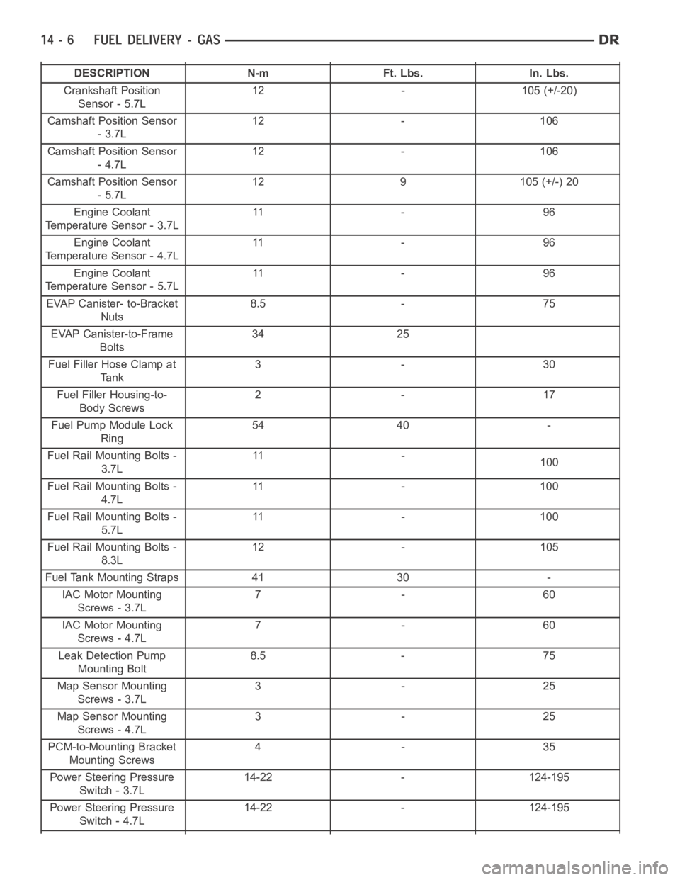
DESCRIPTION N-m Ft. Lbs. In. Lbs.
Crankshaft Position
Sensor - 5.7L12 - 105 (+/-20)
Camshaft Position Sensor
-3.7L12 - 106
Camshaft Position Sensor
-4.7L12 - 106
Camshaft Position Sensor
-5.7L12 9 105 (+/-) 20
Engine Coolant
Temperature Sensor - 3.7L11 - 9 6
Engine Coolant
Temperature Sensor - 4.7L11 - 9 6
Engine Coolant
Temperature Sensor - 5.7L11 - 9 6
EVAP Canister- to-Bracket
Nuts8.5 - 75
EVAP Canister-to-Frame
Bolts34 25
Fuel Filler Hose Clamp at
Tank3-30
Fuel Filler Housing-to-
Body Screws2-17
Fuel Pump Module Lock
Ring54 40 -
Fuel Rail Mounting Bolts -
3.7L11 -
100
Fuel Rail Mounting Bolts -
4.7L11 - 1 0 0
Fuel Rail Mounting Bolts -
5.7L11 - 1 0 0
Fuel Rail Mounting Bolts -
8.3L12 - 105
Fuel Tank Mounting Straps 41 30 -
IAC Motor Mounting
Screws - 3.7L7-60
IAC Motor Mounting
Screws - 4.7L7-60
Leak Detection Pump
Mounting Bolt8.5 - 75
Map Sensor Mounting
Screws - 3.7L3-25
Map Sensor Mounting
Screws - 4.7L3-25
PCM-to-Mounting Bracket
Mounting Screws4-35
Power Steering Pressure
Switch - 3.7L14-22 - 124-195
Power Steering Pressure
Switch - 4.7L14-22 - 124-195