2006 DODGE RAM SRT-10 lock
[x] Cancel search: lockPage 2067 of 5267
CLEANING
CLEANING AND INSPECTION
1. Before cleaning, check for leaks, damage and
cracks.
2. Clean cylinder head and oil passages.
3. Check cylinder head for flatness.
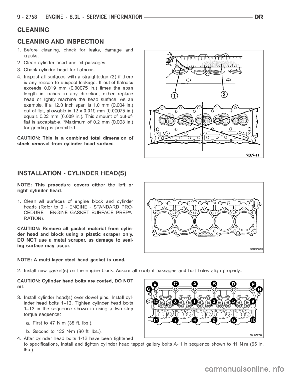
4. Inspect all surfaces with a straightedge (2) if there
is any reason to suspect leakage. If out-of-flatness
exceeds 0.019 mm (0.00075 in.) times the span
length in inches in any direction, either replace
head or lightly machine the head surface. As an
example, if a 12.0 inch span is 1.0 mm (0.004 in.)
out-of-flat, allowable is 12 x 0.019 mm (0.00075 in.)
equals 0.22 mm (0.009 in.). This amount of out-of-
flat is acceptable. *Maximum of 0.2 mm (0.008 in.)
for grinding is permitted.
CAUTION: This is a combined total dimension of
stock removal from cylinder head surface.
INSTALLATION - CYLINDER HEAD(S)
NOTE: This procedure covers either the left or
right cylinder head.
1. Clean all surfaces of engine block and cylinder
heads (Refer to 9 - ENGINE - STANDARD PRO-
CEDURE - ENGINE GASKET SURFACE PREPA-
RATION).
CAUTION: Remove all gasket material from cylin-
der head and block using a plastic scraper only.
DO NOT use a metal scraper, as damage to seal-
ing surface may occur.
NOTE: A multi-layer steel head gasket is used.
2. Install new gasket(s) on the engine block. Assure all coolant passages and bolt holes align properly..
CAUTION: Cylinder head bolts are coated, DO NOT
oil.
3. Install cylinder head(s) over dowel pins. Install cyl-
inder head bolts 1–12. Tighten cylinder head bolts
1–12 in the sequence shown in using a two step
torque sequence:
a. Firstto47Nꞏm(35ft.lbs.).
b. Second to 122 Nꞏm (90 ft. lbs.).
4. After cylinder head bolts 1-12 have been tightened
to specifications, install and tighten cylinder head tappet gallery bolts A-H in sequence shown to 11 Nꞏm (95 in.
lbs.).
Page 2072 of 5267
SPRINGS/SEALS-VALVE
DIAGNOSIS AND TESTING
VA LV E S P R I N G T E S T I N G
The valve springs should be tested whenever
removed for inspection, reconditioning, or replace-
ment.
1. Obtain specifications for spring tension at specified
spring length (Refer to 9 - ENGINE - SPECIFICA-
TIONS).
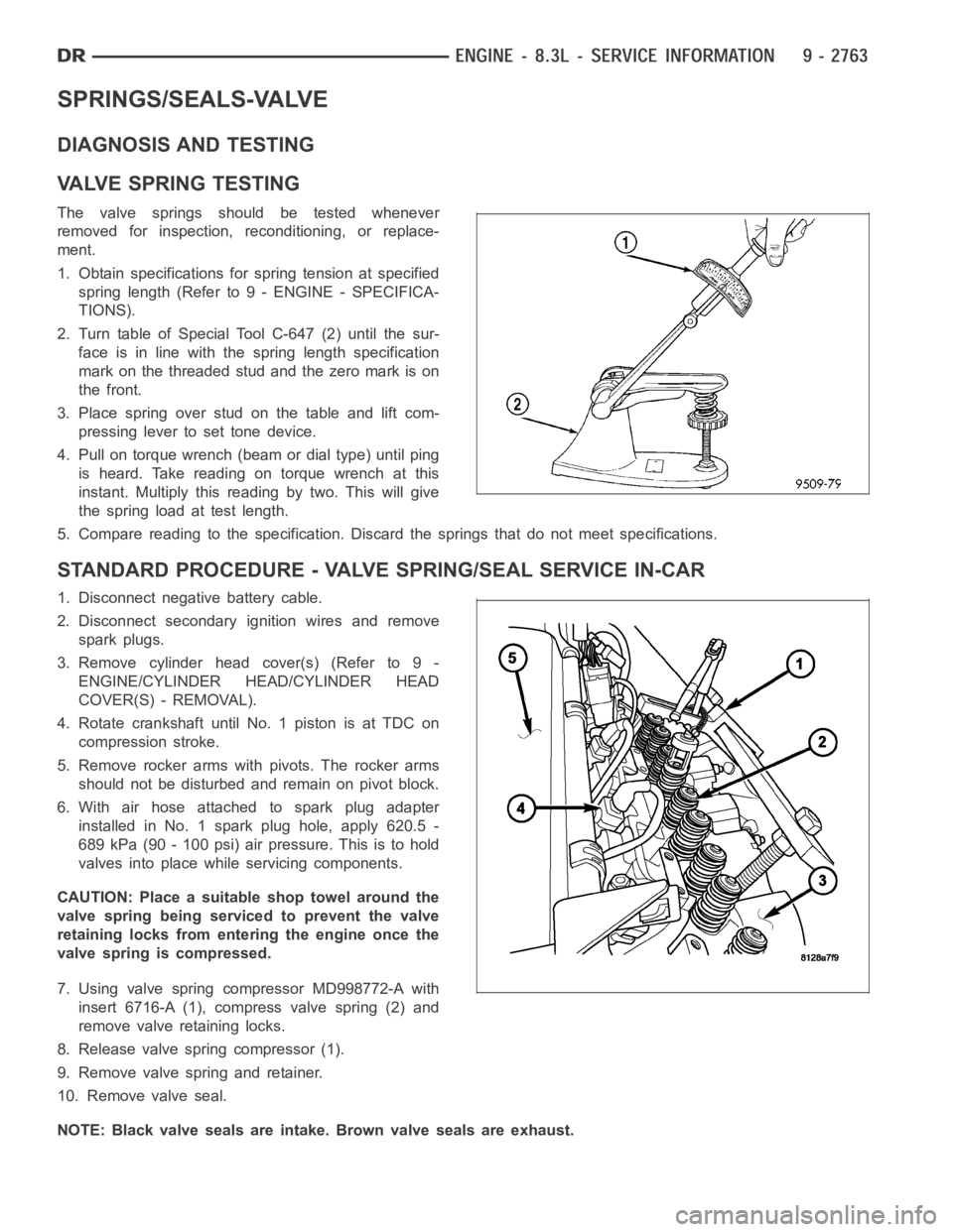
2. Turn table of Special Tool C-647 (2) until the sur-
face is in line with the spring length specification
mark on the threaded stud and the zero mark is on
the front.
3.Placespringoverstudonthetableandliftcom-
pressing lever to set tone device.
4. Pull on torque wrench (beam or dial type) until ping
is heard. Take reading on torque wrench at this
instant. Multiply this reading by two. This will give
the spring load at test length.
5. Compare reading to the specification. Discard the springs that do not meet specifications.
STANDARD PROCEDURE - VALVE SPRING/SEAL SERVICE IN-CAR
1. Disconnect negative battery cable.
2. Disconnect secondary ignition wires and remove
spark plugs.
3. Remove cylinder head cover(s) (Refer to 9 -
ENGINE/CYLINDER HEAD/CYLINDER HEAD
COVER(S) - REMOVAL).
4. Rotate crankshaft until No. 1 piston is at TDC on
compression stroke.
5. Remove rocker arms with pivots. The rocker arms
should not be disturbed and remain on pivot block.
6. With air hose attached to spark plug adapter
installed in No. 1 spark plug hole, apply 620.5 -
689 kPa (90 - 100 psi) air pressure. This is to hold
valves into place while servicing components.
CAUTION: Place a suitable shop towel around the
valve spring being serviced to prevent the valve
retaining locks from entering the engine once the
valve spring is compressed.
7. Using valve spring compressor MD998772-A with
insert 6716-A (1), compress valve spring (2) and
remove valve retaining locks.
8. Release valve spring compressor (1).
9. Remove valve spring and retainer.
10. Remove valve seal.
NOTE: Black valve seals are intake. Brown valve seals are exhaust.
Page 2073 of 5267
11. The intake and exhaust valve stem seals should be pushed firmly and squarely over the valve guide using the
valve stem as guide. Push seal against top of guide. When installing the valve retainer locks, compress the
springonly enoughto install the locks.
CAUTION: Do not pinch seal between retainer and top of valve guide.
12. Follow the same procedure on the remaining 9 cylinders.Make sure piston is at TDC on the cylinder the
valve spring is being removed.
13. Remove spark plug adapter tool.
14. Install rocker arm and pedestal assemblies. Ensure push rods are seated properly under each rocker arm.
Tightenrockerarmboltsto35Nꞏm(26ft.lbs.).
15. Install cylinder head covers (Refer to 9 - ENGINE/CYLINDER HEAD/CYLINDERHEADCOVER(S)-INSTAL-
LATION).
16. Install spark plugs and connect secondary ignition wires.
17. Connect negative battery cable.
REMOVAL
NOTE: Before replacing parts, inspect all related
valvetrain components for damage to prevent
engine misfire.
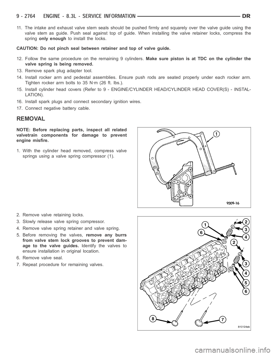
1. With the cylinder head removed, compress valve
springs using a valve spring compressor (1).
2. Remove valve retaining locks.
3. Slowly release valve spring compressor.
4. Remove valve spring retainer and valve spring.
5. Before removing the valves,remove any burrs
from valve stem lock grooves to prevent dam-
age to the valve guides.Identify the valves to
ensure installation in original location.
6. Remove valve seal.
7. Repeat procedure for remaining valves.
Page 2074 of 5267
INSTALLATION
NOTE: Before replacing parts, inspect all related
valvetrain components for damage to prevent
engine misfire.
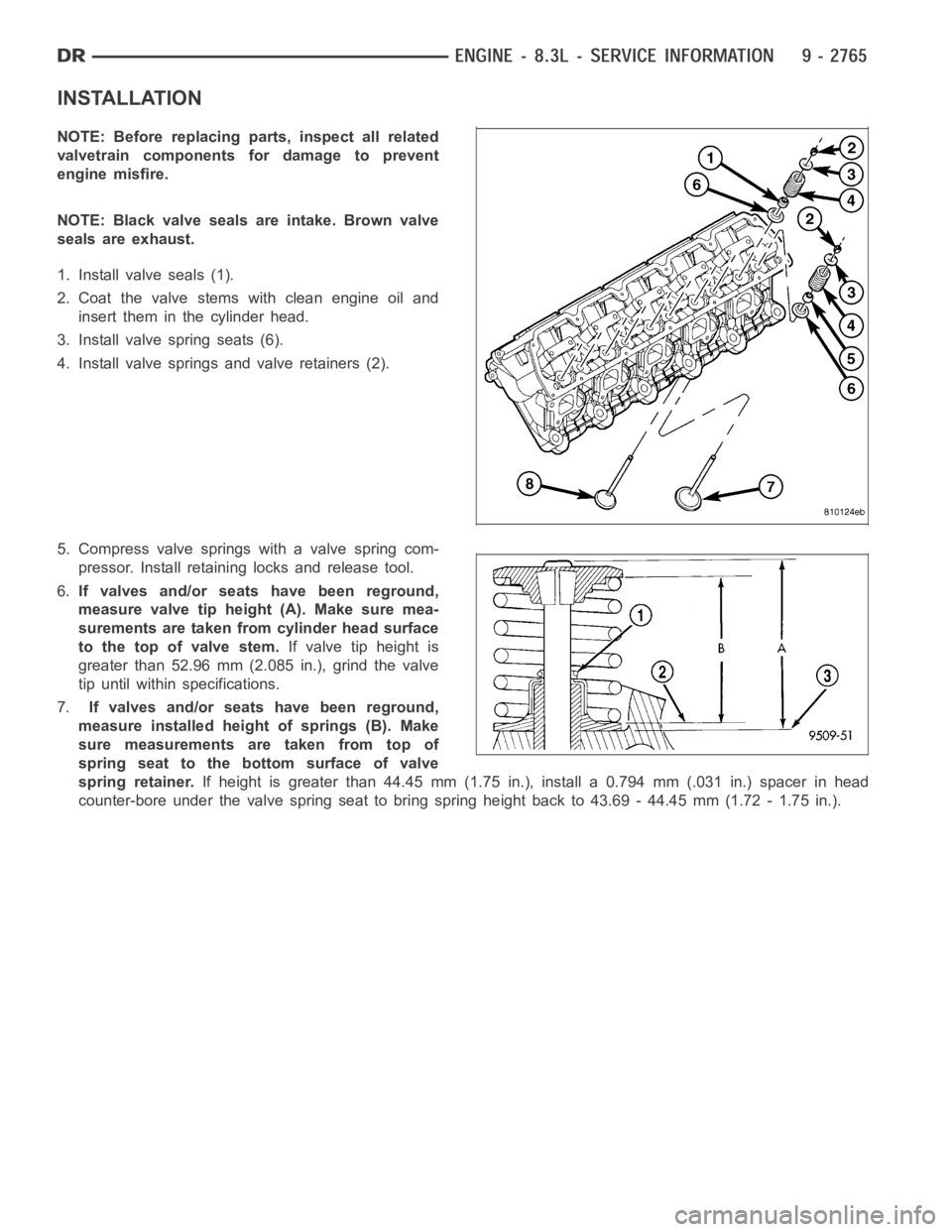
NOTE: Black valve seals are intake. Brown valve
seals are exhaust.
1. Install valve seals (1).
2. Coat the valve stems with clean engine oil and
insert them in the cylinder head.
3. Install valve spring seats (6).
4. Install valve springs and valve retainers (2).
5. Compress valve springs with a valve spring com-
pressor. Install retaining locks and release tool.
6.If valves and/or seats have been reground,
measure valve tip height (A). Make sure mea-
surements are taken from cylinder head surface
to the top of valve stem.If valve tip height is
greater than 52.96 mm (2.085 in.), grind the valve
tip until within specifications.
7.If valves and/or seats have been reground,
measure installed height of springs (B). Make
sure measurements are taken from top of
spring seat to the bottom surface of valve
spring retainer.If height is greater than 44.45 mm (1.75 in.), install a 0.794 mm (.031 in.) spacer in head
counter-bore under the valve spring seat to bring spring height back to 43.69 - 44.45 mm (1.72 - 1.75 in.).
Page 2080 of 5267
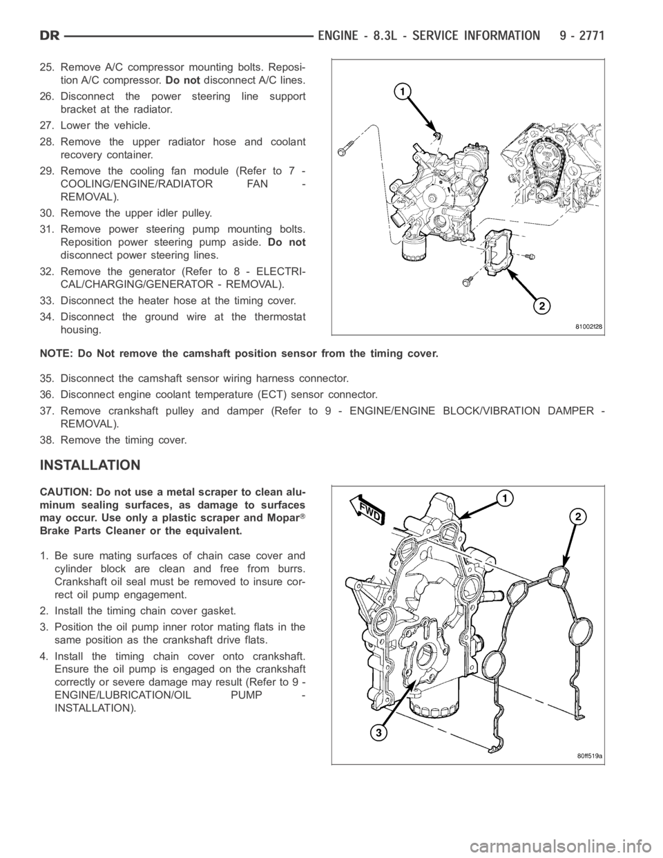
25. Remove A/C compressor mounting bolts. Reposi-
tion A/C compressor.Do notdisconnect A/C lines.
26. Disconnect the power steering line support
bracket at the radiator.
27. Lower the vehicle.
28. Remove the upper radiator hose and coolant
recovery container.
29. Remove the cooling fan module (Refer to 7 -
COOLING/ENGINE/RADIATOR FAN -
REMOVAL).
30. Remove the upper idler pulley.
31. Remove power steering pump mounting bolts.
Reposition power steering pump aside.Do not
disconnect power steering lines.
32. Remove the generator (Refer to 8 - ELECTRI-
CAL/CHARGING/GENERATOR - REMOVAL).
33. Disconnect the heater hose at the timing cover.
34. Disconnect the ground wire at the thermostat
housing.
NOTE: Do Not remove the camshaft position sensor from the timing cover.
35. Disconnect the camshaft sensor wiring harness connector.
36. Disconnect engine coolant temperature (ECT) sensor connector.
37. Remove crankshaft pulley and damper (Refer to 9 - ENGINE/ENGINE BLOCK/VIBRATION DAMPER -
REMOVAL).
38. Remove the timing cover.
INSTALLATION
CAUTION: Do not use a metal scraper to clean alu-
minum sealing surfaces, as damage to surfaces
may occur. Use only a plastic scraper and Mopar
Brake Parts Cleaner or the equivalent.
1. Be sure mating surfaces of chain case cover and
cylinder block are clean and free from burrs.
Crankshaft oil seal must be removed to insure cor-
rect oil pump engagement.
2. Install the timing chain cover gasket.
3. Position the oil pump inner rotor mating flats in the
same position as the crankshaft drive flats.
4. Install the timing chain cover onto crankshaft.
Ensure the oil pump is engaged on the crankshaft
correctly or severe damage may result (Refer to 9 -
ENGINE/LUBRICATION/OIL PUMP -
INSTALLATION).
Page 2081 of 5267

5. Hand start bolts No.1 and No.2.
6. Loosely install A/C compressor mounting bracket.
7. Hand start remaining timing chain cover bolts.
8. Torque timing chain cover bolts in the sequence
showninto23Nꞏm(200in.lbs.).
9. Torque A/C compressor mounting bracket bolts to
23 Nꞏm (200 in. lbs.).
10. Install crankshaft oil seal (Refer to 9 - ENGINE/
ENGINE BLOCK/CRANKSHAFT OIL SEAL -
FRONT - INSTALLATION).
11. Raise vehicle on hoist.
12. Install oil pump pick up tube using anewo-ring.
Torque 1/4–20 bolt to 11 Nꞏm (95 in. lbs.). Torque
5/16–18 nuts to 23 Nꞏm (200 in. lbs.).
13. Support the engine with a jack stand.
14. Install oil pan and drain plug (Refer to 9 -
ENGINE/LUBRICATION/OIL PAN - INSTALLA-
TION).
15. Remove the jackstand.
16. Tighten the engine mount to frame nuts to 102
Nꞏm (75 ft.lbs.).
17. Connect the oil cooler coolant hose to the timing
cover.
18. Connect the oil cooler line (Refer to 9 - ENGINE/
LUBRICATION/OIL COOLER & LINES - STAN-
DARD PROCEDURE).
19. Install the lower radiator hose.
20. Install the flywheel inspection cover.
21. Install the front frame cross member (Refer to 13
- FRAME & BUMPERS/FRAME/FRONT CROSS-
MEMBER - INSTALLATION).
22. Lower vehicle.
23. Position the compressor and install A/C compressor mounting bolts. Torque bolts to 23 Nꞏm (200 in. lbs.).
24. Connect heater hose at timing cover.
25. Install crankshaft damper and pulley (Refer to 9 - ENGINE/ENGINE BLOCK/VIBRATION DAMPER - INSTAL-
LATION).
26. Install generator. Connect electrical connectors.
27. Install the idler pulley.
28. Connect the camshaft position sensor wiring harness connector.
29. Connect engine coolant temperature (ECT) sensor wiring harness connector.
30. Install power steering pump mounting bolts.
31. Install accessory drive belt (Refer to 7 - COOLING/ACCESSORY DRIVE/DRIVE BELTS - INSTALLATION).
32. Install the radiator fan assembly (Refer to 7 - COOLING/ENGINE/RADIATOR FAN - INSTALLATION).
Page 2085 of 5267
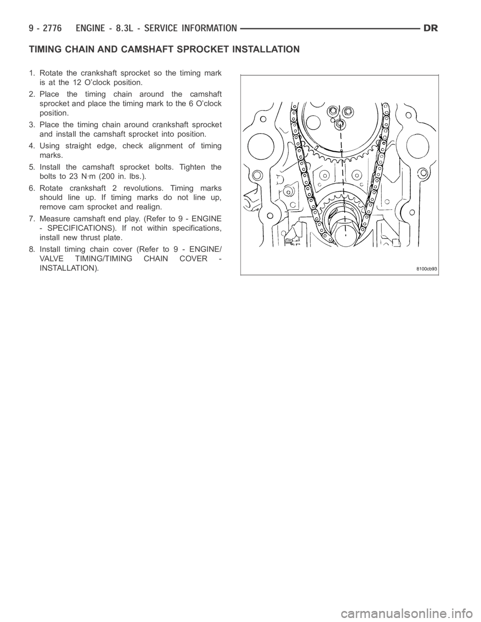
TIMING CHAIN ANDCAMSHAFT SPROCKET INSTALLATION
1. Rotate the crankshaft sprocket so the timing mark
is at the 12 O’clock position.
2. Place the timing chain around the camshaft
sprocket and place the timing mark to the 6 O’clock
position.
3. Place the timing chain around crankshaft sprocket
and install the camshaft sprocket into position.
4. Using straight edge, check alignment of timing
marks.
5. Install the camshaft sprocket bolts. Tighten the
bolts to 23 Nꞏm (200 in. lbs.).
6. Rotate crankshaft 2 revolutions. Timing marks
should line up. If timing marks do not line up,
remove cam sprocket and realign.
7. Measure camshaft end play. (Refer to 9 - ENGINE
- SPECIFICATIONS). If not within specifications,
install new thrust plate.
8. Install timing chain cover (Refer to 9 - ENGINE/
VALVE TIMING/TIMING CHAIN COVER -
INSTALLATION).
Page 2086 of 5267
LUBRICATION
DESCRIPTION
The engine lubrication system is a full-flow filtration pressure feed type.
OPERATION
Engine oil stored in the oil pan is taken in and discharged by an internal geartypeoilpump,whichisdrivenbythe
crankshaft. A pressure relief valve is located in the timing chain case cover; it regulates oil pressure. The oil is
pumped through an oil filter and feeds a main oil gallery. Also, oil is routedtoanexternaloilcooler.Themainoil
gallery feeds oil under pressure to the main bearings, connecting rod bearings, and camshaft bearings. Passages in
the cylinder block feed oil to the hydraulic lifters. The oil then flows through hollow pushrods, which feed the rocker
arm pivots.
DIAGNOSIS AND TESTING
CHECKING ENGINE OIL PRESSURE
1. Remove oil pressure sensor (Refer to 9 - ENGINE/LUBRICATION/OIL PRESSURE SENSOR - REMOVAL).
2. Install oil pressure gauge.
3. Warm engine at high idle until thermostat opens.
CAUTION: If oil pressure is 0 at idle, Do Not Run engine at 3000 RPM.
4. Oil pressure should be 68.9 kPa (10 psi) at idle or 310 - 517 kPa (45 - 75 psi)at 3000 RPM.
5. If oil pressure is 0 at idle, shut off engine. Check for a clogged oil pick-up screen or a pressure relief valve stuck
open.
ENGINE OIL LEAK
Begin with a thorough visual inspection of the engine, particularly at thearea of the suspected leak. If an oil leak
source is not readily identifiable, thefollowingstepsshouldbefollowed:
1. Do not clean or degrease the engine at this time because some solvents maycause rubber to swell, temporarily
stopping the leak.
2. Add an oil soluble dye (use as recommended by manufacturer). Start the engine and let idle for approximately 15
minutes. Check the oil dipstick to make sure the dye is thoroughly mixed as indicated with a bright yellow color
under a black light.
3. Using a black light, inspect the entire engine for fluorescent dye, particularly at the suspected area of oil leak. If
the oil leak is found and identified, repair per service manual instructions.
4. If dye is not observed, drive the vehicle at various speeds for approximately 24 km (15 miles), and repeat inspec-
tion.If the oil leak source is not positively identified at this time, proceed with the air leak detection test
method.
Air Leak Detection Test Method
1. Remove the PCV valve from the IAFM. Cap or plug the PCV valve grommet.
2. Attach an air hose with pressure gauge and regulator to the dipstick tube.
CAUTION: Do not subject the engine assembly to more than 20.6 kPa (3 PSI) of test pressure.
3. Gradually apply air pressure from 6.89 - 17.23 kPa (1 - 2.5 psi) maximum while applying soapy water at the
suspected source. Adjust the regulator to the suitable test pressure thatprovide the best bubbles which will pin-
point the leak source. If the oil leak is detected and identified, repair per service manual procedures.
4. If the leakage occurs at the rear oil seal area, refer to the section, Inspection for Rear Seal Area Leak.
5. If no leaks are detected, turn off the air supply and remove the air hose and all plugs and caps. Install the PCV
valve.
6. Clean the oil off the suspect oil leak area using a suitable solvent. Drive the vehicle at various speeds approx-
imately 24 km (15 miles). Inspect the engine for signs of an oil leak by usinga black light.