Page 2087 of 5267

INSPECTION FOR REAR SEAL AREA LEAKS
Since it is sometimes difficult to determine the source of an oil leak in therear seal area of the engine, a more
involved inspection is necessary. The following steps should be followedto help pinpoint the source of the leak.
If the leakage occurs at the crankshaft rear oil seal area:
1. Disconnect the battery.
2. Raise the vehicle.
3. Remove torque converter or clutch housing cover and inspect rear of block for evidence of oil. Use a black light
to check for the oil leak:
a. Circular spray pattern generally indicates seal leakage or crankshaftdamage.
b. Where leakage tends to run straight down, possible causes are a porous block, distributor seal, camshaft
bore cup plugs oil galley pipe plugs, oil filter runoff, and main bearing cap to cylinder block mating surfaces.
4. If no leaks are detected, pressurize the crankcase as outlined in the, Inspection (Engine oil Leaks in general)
CAUTION: Do not exceed 20.6 kPa (3 psi).
5. If the leak is not detected, very slowly turn the crankshaft and watch forleakage. If a leak is detected between
the crankshaft and seal while slowly turning the crankshaft, it is possible the crankshaft seal surface is damaged.
The seal area on the crankshaft could have minor nicks or scratches that canbe polished out with emery cloth.
CAUTION: Use extreme caution when crankshaft polishing is necessary to remove minor nicks and
scratches. The crankshaft seal flange is especially machined to complement the function of the rear oil seal.
6. For bubbles that remain steady with shaft rotation, no further inspection can be done until disassembled.
Page 2095 of 5267
2. Apply an 1/8 in. bead of Mopar Engine RTV at the two joints between the cylinder block to timing chain case
cover and the two joints between the rear main seal retainer and engine block.
3. Position oil pan and gasket to engine block, seat the oil level indicatortube in the oil pan and hand start all
fasteners.
4. Tighten the transmission to oil pan bolts in finger
tight.
5. Torque 5/16-18 oil pan bolts to 23 Nꞏm (200 in.
lbs.). Torque 1/4-20 oil pan bolts to 11 Nꞏm (95 in
lbs.).
6. Torque transmission to oil pan bolts to 23 Nꞏm (200
in. lbs.).
7. Lower the engine.
8. Install and tighten engine mount through bolts to
102 Nꞏm (75 ft. lbs.).
9. Install flywheel inspection cover.
Page 2104 of 5267

BLOCK-ENGINE
DESCRIPTION
The cylinder block is made of a sand-cast aluminum alloy. The cylinder block has interference-fit cast iron cylinder
liners. The cylinder liners are thermally installed during block manufacturing; they are not serviceable items.
Six iron main bearing caps use four bolts per cap; two vertical and two horizontal. A crankshaft oil scraper is
attached to the main bearing caps via extended main bearing cap bolts and nuts.
STANDARD PROCEDURE - CYLINDER BORE HONING
Before honing, stuff plenty of clean shop towels under
the bores and over the crankshaft to keep abrasive
materials from entering the crankshaft area.
1. Used carefully, the Cylinder Bore Sizing Hone
C-823, equipped with 220 grit stones, is the best
tool for this job. In addition to deglazing, it will
reduce taper and out-of-round, as well as removing
light scuffing, scoring and scratches. Usually, a few
strokes will clean up a bore and maintain the
required limits.
CAUTION: DO NOT use rigid type hones to remove
cylinder wall glaze.
2. Deglazing of the cylinder walls may be done if the
cylinder bore is straight and round. Use a cylinder
surfacing hone, Honing Tool C-3501, equipped with
280 grit stones (C-3501-3810). about 20-60
strokes, depending on the bore condition, will be
sufficient to provide a satisfactory surface. Using
honing oil C-3501-3880, or a light honing oil, avail-
able from major oil distributors.
CAUTION: DO NOT use engine or transmission oil, mineral spirits, or kerosene.
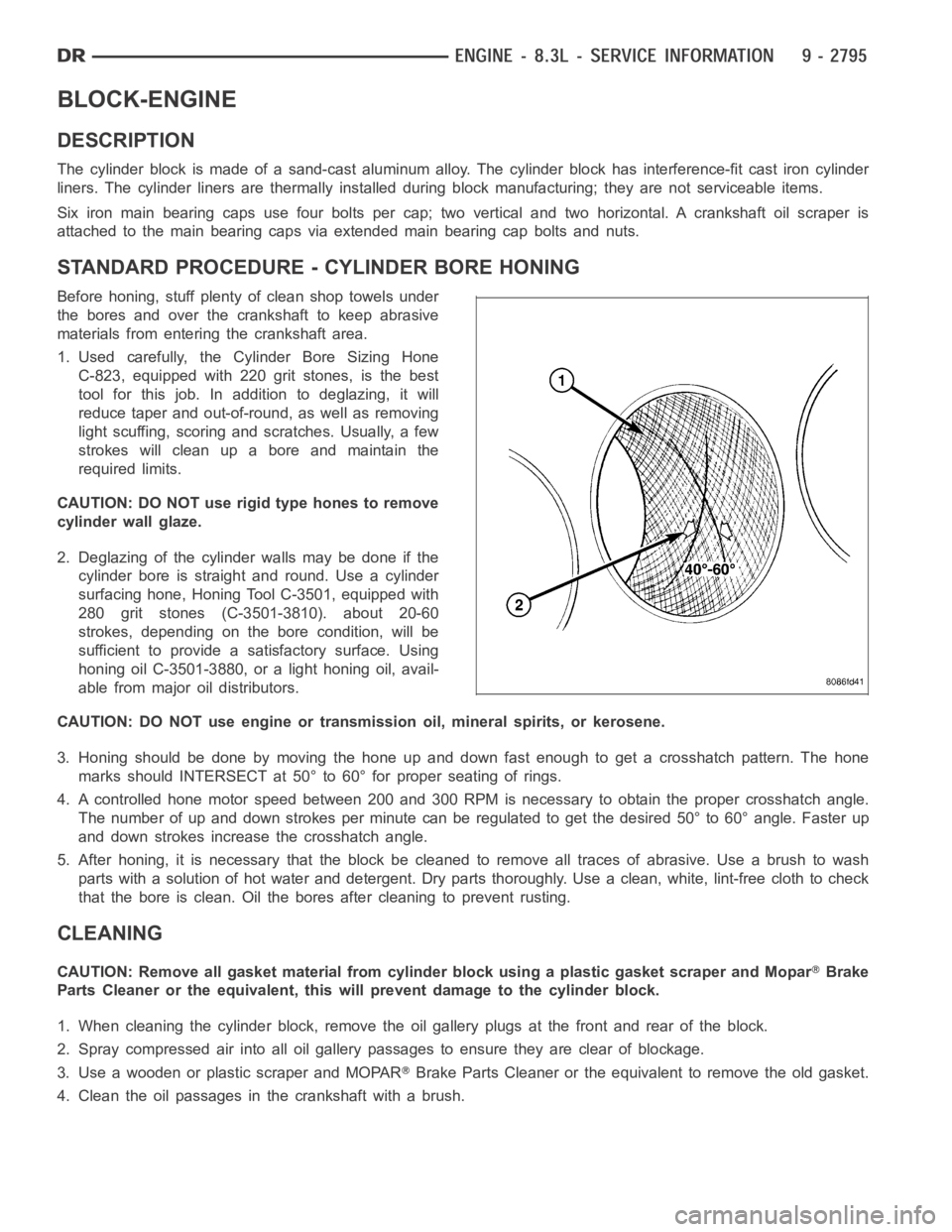
3. Honing should be done by moving the hone up and down fast enough to get a crosshatch pattern. The hone
marks should INTERSECT at 50° to 60° for proper seating of rings.
4. A controlled hone motor speed between 200 and 300 RPM is necessary to obtain the proper crosshatch angle.
The number of up and down strokes per minute can be regulated to get the desired 50° to 60° angle. Faster up
and down strokes increase the crosshatch angle.
5. After honing, it is necessary that the block be cleaned to remove all traces of abrasive. Use a brush to wash
parts with a solution of hot water and detergent. Dry parts thoroughly. Usea clean, white, lint-free cloth to check
that the bore is clean. Oil the bores after cleaning to prevent rusting.
CLEANING
CAUTION: Remove all gasket material from cylinder block using a plastic gasket scraper and MoparBrake
Parts Cleaner or the equivalent, this will prevent damage to the cylinder block.
1. When cleaning the cylinder block, remove the oil gallery plugs at the front and rear of the block.
2. Spray compressed air into all oil gallery passages to ensure they are clear of blockage.
3. Use a wooden or plastic scraper and MOPAR
Brake Parts Cleaner or the equivalent to remove the old gasket.
4. Clean the oil passages in the crankshaft with a brush.
Page 2106 of 5267
HYDRAULIC TAPPETS
DESCRIPTION
The roller type design hydraulic tappets (3) are posi-
tioned in the cylinder block. Roller tappet alignment is
maintained by machined flats on tappet body being fit-
ted in pairs into ten aligning yokes (2).
REMOVAL
1.Removecylinderhead(s)(Referto9-ENGINE/
CYLINDER HEAD - REMOVAL).
NOTE: If tappets (3) are to be reused, identify tap-
pet location to ensure installation in original loca-
tion.
2. Remove tappet aligning yoke bolt (1).
3. Remove tappets (3) from bores.
CAUTION: Do not disassemble tappets.
Page 2107 of 5267
INSTALLATION
1. Lubricate tappets.
2. Install tappets in their original positions with oil
holes (1) facing up.
CAUTION: The “handle” on the tappet aligning
yoke must be installed in the outboard position;
i.e. toward the cylinders.
3. With roller tappets in proper position, install align-
ing yoke assemblies. Apply Mopar
Lock & Seal
Adhesive (Medium Strength Threadlocker) to the
screwsandtightento11Nꞏm(95in.lbs.).
4. Install cylinder heads (Refer to 9 - ENGINE/CYLIN-
DER HEAD - INSTALLATION).
5. Start and operate engine. Warm up to normal oper-
ating temperature.
CAUTION: To prevent damage to valve mecha-
nism, engine must not be run above fast idle until
all hydraulic tappets have filled with oil and have
become quiet.
Page 2108 of 5267

CAMSHAFT
REMOVAL
1. Perform the fuel pressure relief procedure (Refer to
14 - FUEL SYSTEM/FUEL DELIVERY - STAN-
DARD PROCEDURE).
2. Disconnect the negative battery cable.
3. Raise and support the vehicle.
4. Remove the front engine shield.
5. Drain the cooling system
6. Drain the power steering fluid.
7. Remove the oil pan (Refer to 9 - ENGINE/LUBRI-
CATION/OIL PAN - REMOVAL).
8. Lower the vehicle.
9. Remove the radiator and radiator fan assembly
(Refer to 7 - COOLING/ENGINE/RADIATOR -
REMOVAL).
10. Remove intake manifold (Refer to 9 - ENGINE/
MANIFOLDS/INTAKE MANIFOLD - REMOVAL).
11. Remove cylinder head covers (Refer to 9 -
ENGINE/CYLINDER HEAD/CYLINDER HEAD
COVER(S) - REMOVAL).
12. Remove timing chain cover (Refer to 9 - ENGINE/
VALVE TIMING/TIMING CHAIN COVER - REMOVAL).
13. Remove rocker arm assemblies.
NOTE: Identify each push rod to be replaced in its original location.
14. Remove push rods.
15. Remove cylinder heads (Refer to 9 - ENGINE/CYLINDER HEAD - REMOVAL).
16. Remove hydraulic tappets (Refer to 9 - ENGINE/ENGINE BLOCK/HYDRAULICTAPPETS - REMOVAL).
17. Remove timing chain and camshaft sprocket (Refer to 9 - ENGINE/VALVE TIMING/TIMING CHAIN AND
SPROCKETS - REMOVAL).
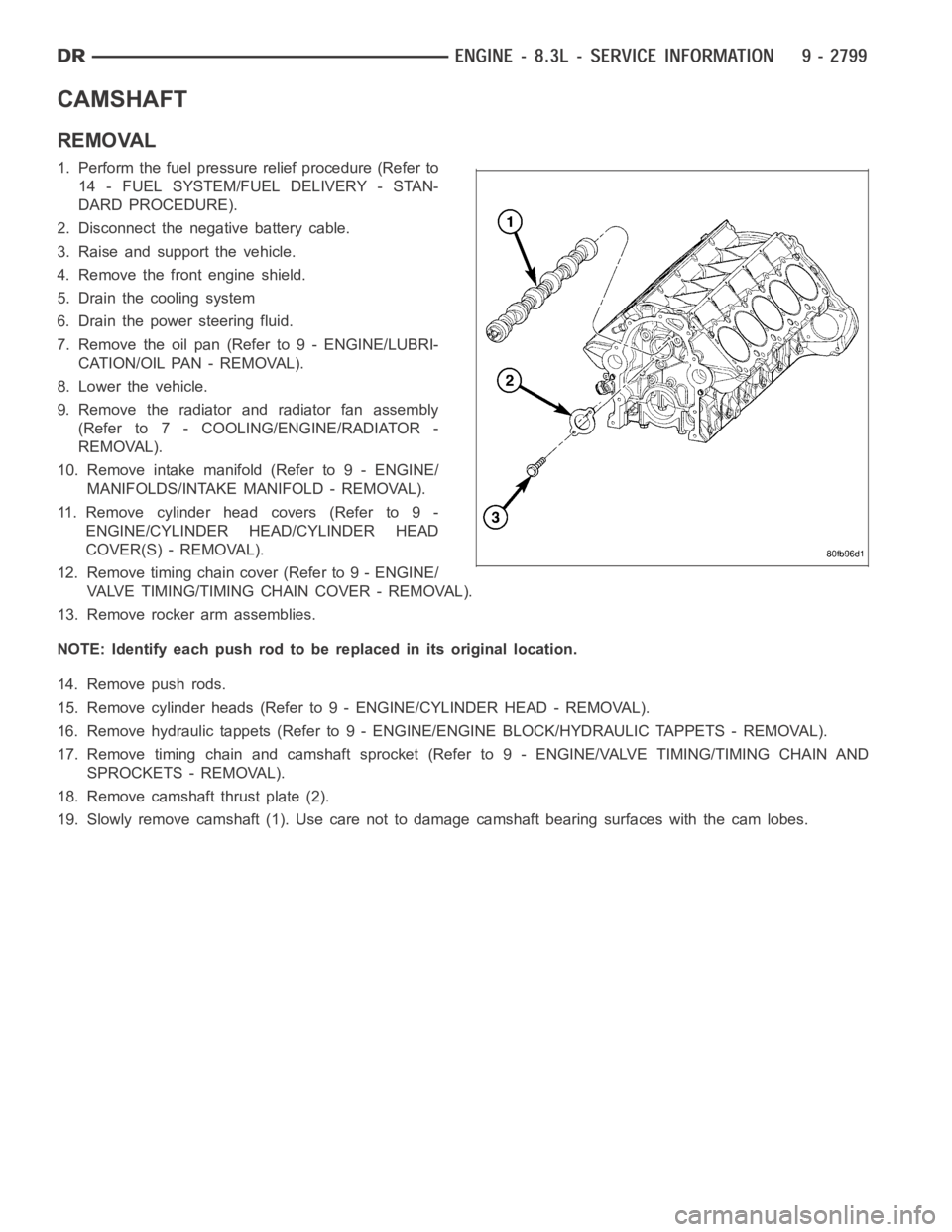
18. Remove camshaft thrust plate (2).
19. Slowly remove camshaft (1). Use care not to damage camshaft bearing surfaces with the cam lobes.
Page 2109 of 5267

INSTALLATION
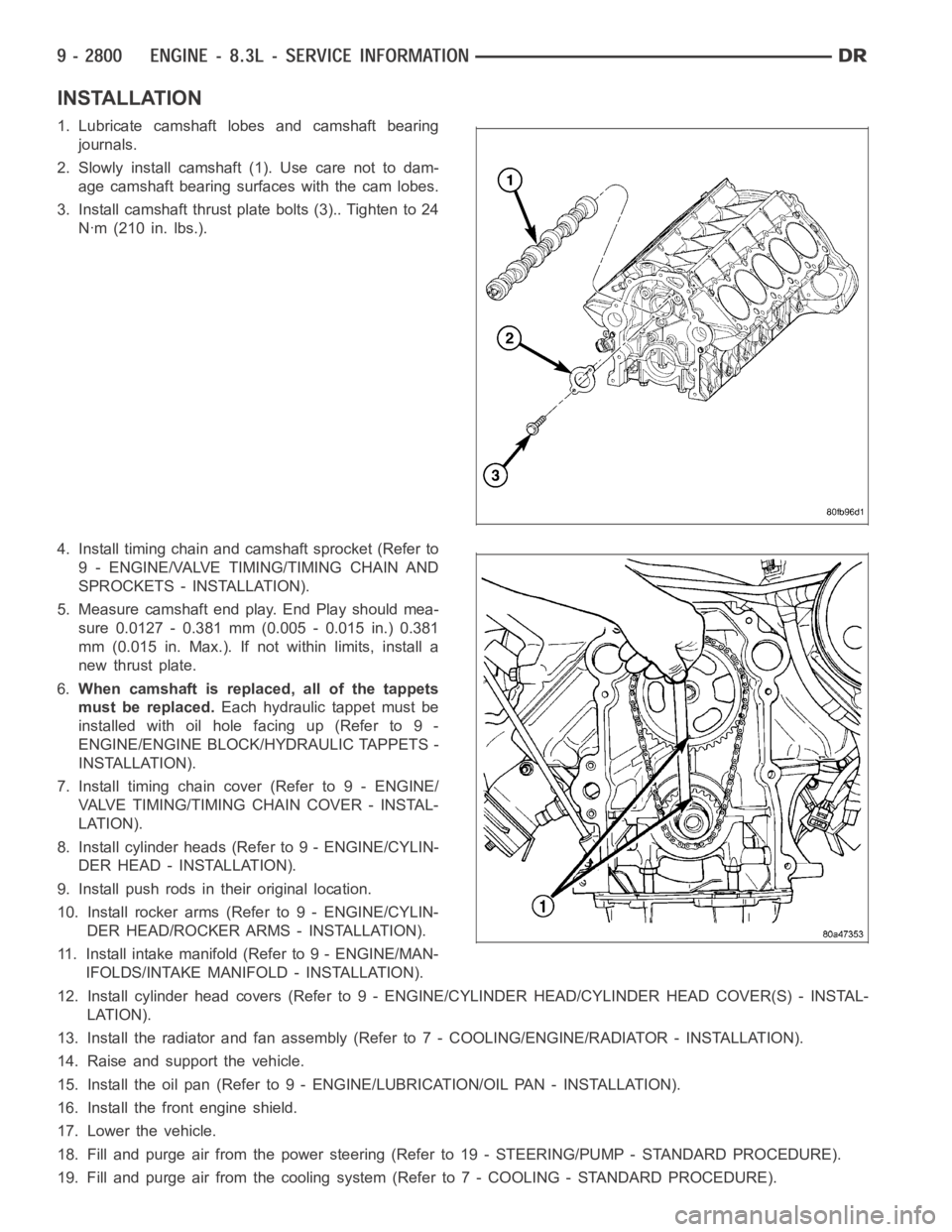
1. Lubricate camshaft lobes and camshaft bearing
journals.
2. Slowly install camshaft (1). Use care not to dam-
age camshaft bearing surfaces with the cam lobes.
3. Install camshaft thrust plate bolts (3).. Tighten to 24
Nꞏm (210 in. lbs.).
4. Install timing chain and camshaft sprocket (Refer to
9 - ENGINE/VALVE TIMING/TIMING CHAIN AND
SPROCKETS - INSTALLATION).
5. Measure camshaft end play. End Play should mea-
sure 0.0127 - 0.381 mm (0.005 - 0.015 in.) 0.381
mm (0.015 in. Max.). If not within limits, install a
new thrust plate.
6.When camshaft is replaced, all of the tappets
must be replaced.Each hydraulic tappet must be
installed with oil hole facing up (Refer to 9 -
ENGINE/ENGINE BLOCK/HYDRAULIC TAPPETS -
INSTALLATION).
7. Install timing chain cover (Refer to 9 - ENGINE/
VALVE TIMING/TIMINGCHAIN COVER - INSTAL-
LATION).
8. Install cylinder heads (Refer to 9 - ENGINE/CYLIN-
DER HEAD - INSTALLATION).
9. Install push rods in their original location.
10. Install rocker arms (Refer to 9 - ENGINE/CYLIN-
DER HEAD/ROCKER ARMS - INSTALLATION).
11. Install intake manifold (Refer to 9 - ENGINE/MAN-
IFOLDS/INTAKE MANIFOLD - INSTALLATION).
12. Install cylinder head covers (Refer to 9 - ENGINE/CYLINDER HEAD/CYLINDER HEAD COVER(S) - INSTAL-
LATION).
13. Install the radiator and fan assembly (Refer to 7 - COOLING/ENGINE/RADIATOR - INSTALLATION).
14. Raise and support the vehicle.
15. Install the oil pan (Refer to 9 - ENGINE/LUBRICATION/OIL PAN - INSTALLATION).
16. Install the front engine shield.
17. Lower the vehicle.
18. Fill and purge air from the power steering (Refer to 19 - STEERING/PUMP -STANDARD PROCEDURE).
19. Fill and purge air from the coolingsystem (Refer to 7 - COOLING - STANDARD PROCEDURE).
Page 2112 of 5267
MEASURING CONNECTING ROD SIDE CLEARANCE
1. Using a feeler gauge, check connecting rod side
clearance. (Refer to 9 - ENGINE - SPECIFICA-
TIONS) for connecting rod side clearance
specifications.
REMOVAL
NOTE: Pistons and connecting rods are to be
removed as an assembly from top of cylinder
block.
1. Remove engine (Refer to 9 - ENGINE - REMOVAL)
and place in a suitable engine stand.
2. Remove cylinder heads (Refer to 9 - ENGINE/CYL-
INDER HEAD - REMOVAL).
3. Remove oil pan (Refer to 9 - ENGINE/LUBRICA-
TION/OIL PAN - REMOVAL).
4. Remove the oil pump pick up tube (2)