2006 DODGE RAM SRT-10 lock
[x] Cancel search: lockPage 2031 of 5267
STANDARD PROCEDURE
ENGINE CORE AND OIL GALLERY PLUGS
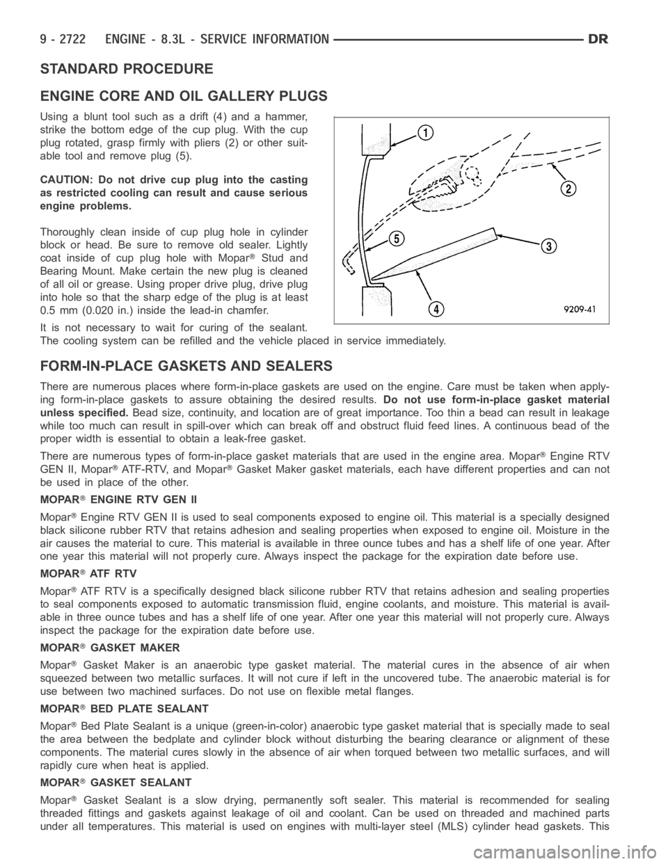
Using a blunt tool such as a drift (4) and a hammer,
strike the bottom edge of the cup plug. With the cup
plug rotated, grasp firmly with pliers (2) or other suit-
able tool and remove plug (5).
CAUTION: Do not drive cup plug into the casting
as restricted cooling can result and cause serious
engine problems.
Thoroughly clean inside of cup plug hole in cylinder
block or head. Be sure to remove old sealer. Lightly
coat inside of cup plug hole with Mopar
Stud and
Bearing Mount. Make certain the new plug is cleaned
of all oil or grease. Using proper drive plug, drive plug
into hole so that the sharp edge of the plug is at least
0.5 mm (0.020 in.) inside the lead-in chamfer.
It is not necessary to wait for curing of the sealant.
The cooling system can be refilled and the vehicle placed in service immediately.
FORM-IN-PLACE GASKETS AND SEALERS
There are numerous places where form-in-place gaskets are used on the engine. Care must be taken when apply-
ing form-in-place gaskets to assure obtaining the desired results.Do not use form-in-place gasket material
unless specified.Bead size, continuity, and location are of great importance. Too thin a bead can result in leakage
while too much can result in spill-overwhich can break off and obstruct fluid feed lines. A continuous bead of the
proper width is essential to obtain a leak-free gasket.
There are numerous types of form-in-place gasket materials that are used in the engine area. Mopar
Engine RTV
GEN II, Mopar
ATF-RTV, and MoparGasket Maker gasket materials, each have different properties and can not
be used in place of the other.
MOPAR
ENGINE RTV GEN II
Mopar
Engine RTV GEN II is used to seal components exposed to engine oil. This material is a specially designed
black silicone rubber RTV that retains adhesion and sealing properties when exposed to engine oil. Moisture in the
air causes the material to cure. This material is available in three ounce tubes and has a shelf life of one year. After
one year this material will not properly cure. Always inspect the package for the expiration date before use.
MOPAR
AT F R T V
Mopar
ATF RTV is a specifically designed black silicone rubber RTV that retains adhesion and sealing properties
to seal components exposed to automatic transmission fluid, engine coolants, and moisture. This material is avail-
able in three ounce tubes and has a shelf life of one year. After one year thismaterial will not properly cure. Always
inspect the package for the expiration date before use.
MOPAR
GASKET MAKER
Mopar
Gasket Maker is an anaerobic type gasket material. The material cures in the absence of air when
squeezed between two metallic surfaces. It will not cure if left in the uncovered tube. The anaerobic material is for
use between two machined surfaces. Do not use on flexible metal flanges.
MOPAR
BED PLATE SEALANT
Mopar
Bed Plate Sealant is a unique (green-in-color) anaerobic type gasket material that is specially made to seal
the area between the bedplate and cylinder block without disturbing the bearing clearance or alignment of these
components. The material cures slowly in the absence of air when torqued between two metallic surfaces, and will
rapidly cure when heat is applied.
MOPAR
GASKET SEALANT
Mopar
Gasket Sealant is a slow drying, permanently soft sealer. This material isrecommended for sealing
threaded fittings and gaskets against leakage of oil and coolant. Can be used on threaded and machined parts
under all temperatures. This material is used on engines with multi-layersteel (MLS) cylinder head gaskets. This
Page 2032 of 5267
material also will prevent corrosion. MoparGasket Sealant is available in a 13 oz. aerosol can or 4 oz./16 oz. can
w/applicator.
FORM-IN-PLACE GASKET AND SEALER APPLICATION
MoparGasket Maker material should be applied sparingly 1 mm (0.040 in.) diameter or less of sealant to one
gasket surface. Be certain the material surrounds each mounting hole. Excess material can easily be wiped off.
Components should be torqued in place within 15 minutes. The use of a locating dowel is recommended during
assembly to prevent smearing material off the location.
Mopar
Engine RTV GEN II or ATF RTV gasket material should be applied in a continuous bead approximately 3
mm (0.120 in.) in diameter. All mounting holes must be circled. For corner sealing,a3.17mmor6.35mm(1/8in.
or 1/4 in.) drop is placed in the center of the gasket contact area. Uncured sealant may be removed with a shop
towel. Components should be torqued in place while the sealant is still wettothetouch(within10minutes).The
usage of a locating dowel is recommended during assembly to prevent smearing material off the location.
Mopar
Gasket Sealant in an aerosol can should be applied using a thin, even coat sprayed completely over both
surfaces to be joined, and both sides of a gasket. Then proceed with assembly. Material in a can w/applicator can
be brushed on evenly over the sealing surfaces. Material in an aerosol can shouldbeusedonengineswithmulti-
layer steel gaskets.
ENGINE GASKET SURFACE PREPARATION
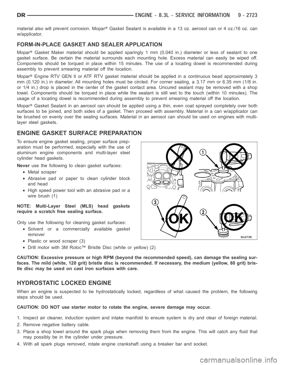
To ensure engine gasket sealing, proper surface prep-
aration must be performed, especially with the use of
aluminum engine components and multi-layer steel
cylinder head gaskets.
Neveruse the following to clean gasket surfaces:
Metal scraper
Abrasive pad or paper to clean cylinder block
and head
High speed power tool with an abrasive pad or a
wire brush (1)
NOTE: Multi-Layer Steel (MLS) head gaskets
require a scratch free sealing surface.
Only use the following for cleaning gasket surfaces:
Solvent or a commercially available gasket
remover
Plastic or wood scraper (3)
Drill motor with 3M Roloc™ Bristle Disc (white or yellow) (2)
CAUTION: Excessive pressure or high RPM (beyond the recommended speed), can damage the sealing sur-
faces. The mild (white, 120 grit) bristle disc is recommended. If necessary, the medium (yellow, 80 grit) bris-
tle disc may be used on cast iron surfaces with care.
HYDROSTATIC LOCKED ENGINE
When an engine is suspected to be hydrostatically locked, regardless of what caused the problem, the following
steps should be used.
CAUTION: DO NOT use starter motor to rotate the engine, severe damage may occur.
1. Inspect air cleaner, induction system and intake manifold to ensure system is dry and clear of foreign material.
2. Remove negative battery cable.
3. Place a shop towel around the spark plugs when removing them from the engine. This will catch any fluid that
may possibly be in the cylinder under pressure.
4. With all spark plugs removed, rotate engine crankshaft using a breaker bar and socket.
Page 2040 of 5267
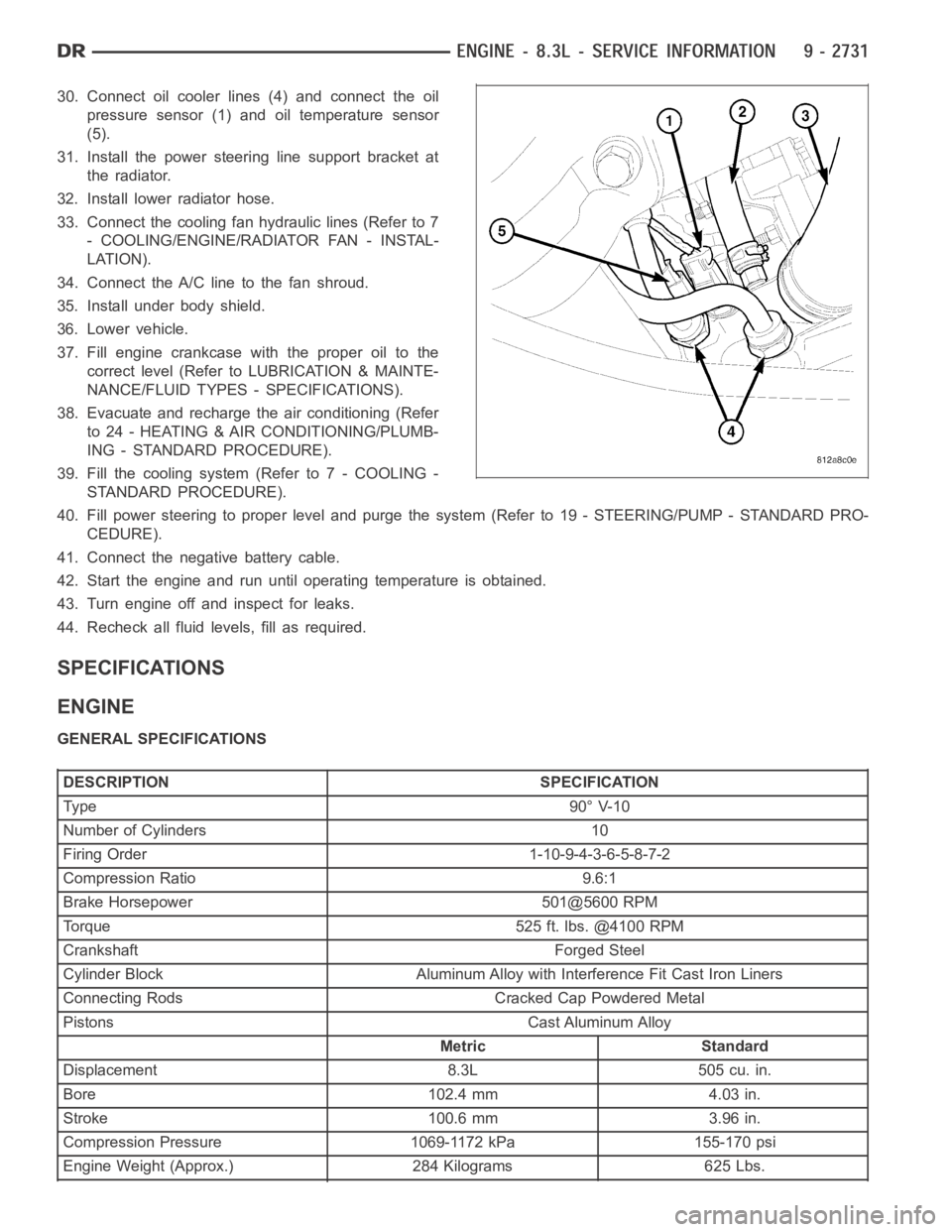
30. Connect oil cooler lines (4) and connect the oil
pressure sensor (1) and oil temperature sensor
(5).
31. Install the power steering line support bracket at
the radiator.
32. Install lower radiator hose.
33. Connect the cooling fan hydraulic lines (Refer to 7
- COOLING/ENGINE/RADIATOR FAN - INSTAL-
LATION).
34. Connect the A/C line to the fan shroud.
35. Install under body shield.
36. Lower vehicle.
37. Fill engine crankcase with the proper oil to the
correct level (Refer to LUBRICATION & MAINTE-
NANCE/FLUID TYPES - SPECIFICATIONS).
38. Evacuate and recharge the air conditioning (Refer
to 24 - HEATING & AIR CONDITIONING/PLUMB-
ING - STANDARD PROCEDURE).
39. Fill the cooling system (Refer to 7 - COOLING -
STANDARD PROCEDURE).
40. Fill power steering to proper leveland purge the system (Refer to 19 - STEERING/PUMP - STANDARD PRO-
CEDURE).
41. Connect the negative battery cable.
42. Start the engine and run until operating temperature is obtained.
43. Turn engine off and inspect for leaks.
44. Recheck all fluid levels, fill as required.
SPECIFICATIONS
ENGINE
GENERAL SPECIFICATIONS
DESCRIPTION SPECIFICATION
Ty pe 9 0° V-1 0
Number of Cylinders 10
Firing Order 1-10-9-4-3-6-5-8-7-2
Compression Ratio 9.6:1
Brake Horsepower 501@5600 RPM
Torque 525 ft. lbs. @4100 RPM
Crankshaft Forged Steel
Cylinder Block Aluminum Alloy with Interference Fit Cast Iron Liners
Connecting Rods Cracked Cap Powdered Metal
Pistons Cast Aluminum Alloy
Metric Standard
Displacement 8.3L 505 cu. in.
Bore 102.4 mm 4.03 in.
Stroke 100.6 mm 3.96 in.
Compression Pressure 1069-1172 kPa 155-170 psi
Engine Weight (Approx.) 284 Kilograms 625 Lbs.
Page 2041 of 5267
CYLINDER BLOCK
DESCRIPTIONSPECIFICATION
Metric Standard
Cylinder Bore Diameter 102.356-102.368 mm 4.02975-4.03025 in.
Out of Round (Max.) 0.051 mm 0.002 in.
Taper (Max.) 0.038 mm 0.0015 in.
Tappet Bore Diameter 22.974-22.992 mm 0.9045-0.9052 in.
Block Length 693.7 mm 27.310 in.
Block Height 240.8 mm 9.48 in.
CRANKSHAFT
DESCRIPTIONSPECIFICATION
Metric Standard
Connecting Rod Journal Diameter 53.990-54.008 mm 2.1256-2.1263 in.
Out-of-Round (Max.) 0.013 mm 0.0005 in.
Taper (Max.) 0.013 mm 0.0005 in
End Play 0.051-0.178 mm 0.002-0.007 in.
Desired 0.13 mm 0.005 in.
Wear Limit 0.254 mm 0.010 in.
Main Bearing Clearance 1-6 0.025-0.051 mm 0.001-0.002 in.
Wear Limit 0.076 mm 0.003 in.
MAIN BEARING JOURNALS
DESCRIPTIONSPECIFICATION
Metric Standard
Diameter-High 76.233-76.246 mm 3.0013-3.0018 in.
Diameter-Low 76.220-76.223 mm 3.0008-3.0013 in.
Out of Round (Max.) 0.013 mm 0.0005 in
CONNECTING RODS
DESCRIPTIONSPECIFICATION
Metric Standard
Bearing Clearance 0.005-0.074 mm. 0.0002-0.0029 in.
Desired 0.0381mm 0.0015in.
Wear Limit 0.0889 mm 0.0035 in.
Piston Pin Boar Diameter 23.940-23.978 mm 0.9425-0.9440 in.
Side Clearance (Two Rods) 0.25-0.46 mm 0.010-0.018 in.
Wear Limit 0.51 mm 0.020 in.
Total Weight (Less Bearing) 598.4 grams 21.11 oz.
PISTONS
Page 2043 of 5267
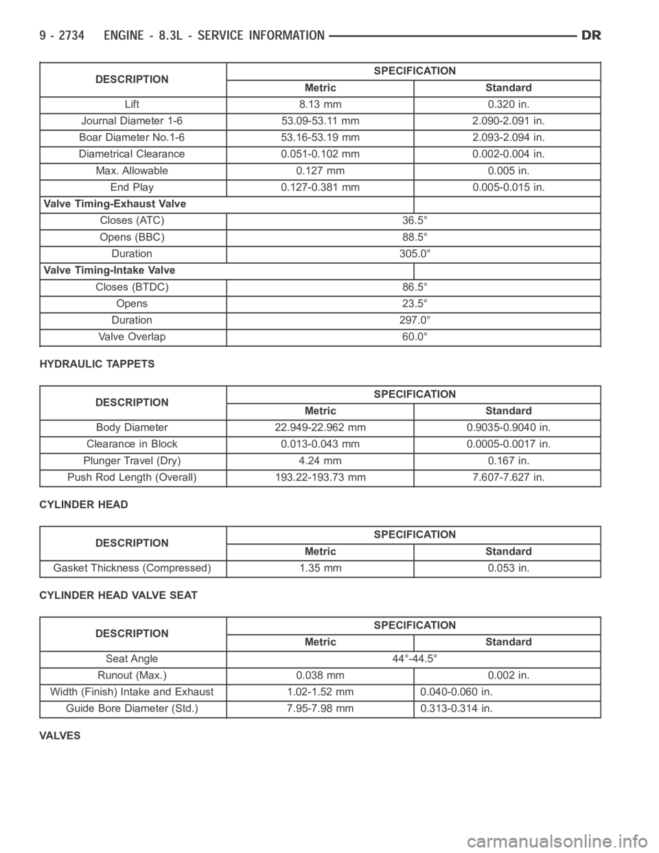
DESCRIPTIONSPECIFICATION
Metric Standard
Lift 8.13 mm 0.320 in.
Journal Diameter 1-6 53.09-53.11 mm 2.090-2.091 in.
Boar Diameter No.1-6 53.16-53.19 mm 2.093-2.094 in.
Diametrical Clearance 0.051-0.102 mm 0.002-0.004 in.
Max. Allowable 0.127 mm 0.005 in.
End Play 0.127-0.381 mm 0.005-0.015 in.
Valve Timing-Exhaust Valve
Closes (ATC) 36.5°
Opens (BBC) 88.5°
Duration 305.0°
Valve Timing-Intake Valve
Closes (BTDC) 86.5°
Opens 23.5°
Duration 297.0°
Valve Overlap 60.0°
HYDRAULIC TAPPETS
DESCRIPTIONSPECIFICATION
Metric Standard
Body Diameter 22.949-22.962 mm 0.9035-0.9040 in.
Clearance in Block 0.013-0.043 mm 0.0005-0.0017 in.
Plunger Travel (Dry) 4.24 mm 0.167 in.
Push Rod Length (Overall) 193.22-193.73 mm 7.607-7.627 in.
CYLINDER HEAD
DESCRIPTIONSPECIFICATION
Metric Standard
Gasket Thickness (Compressed) 1.35 mm 0.053 in.
CYLINDER HEAD VALVE SEAT
DESCRIPTIONSPECIFICATION
Metric Standard
Seat Angle 44°-44.5°
Runout (Max.) 0.038 mm 0.002 in.
Width (Finish) Intake and Exhaust 1.02-1.52 mm 0.040-0.060 in.
Guide Bore Diameter (Std.) 7.95-7.98 mm 0.313-0.314 in.
VA LV E S
Page 2045 of 5267
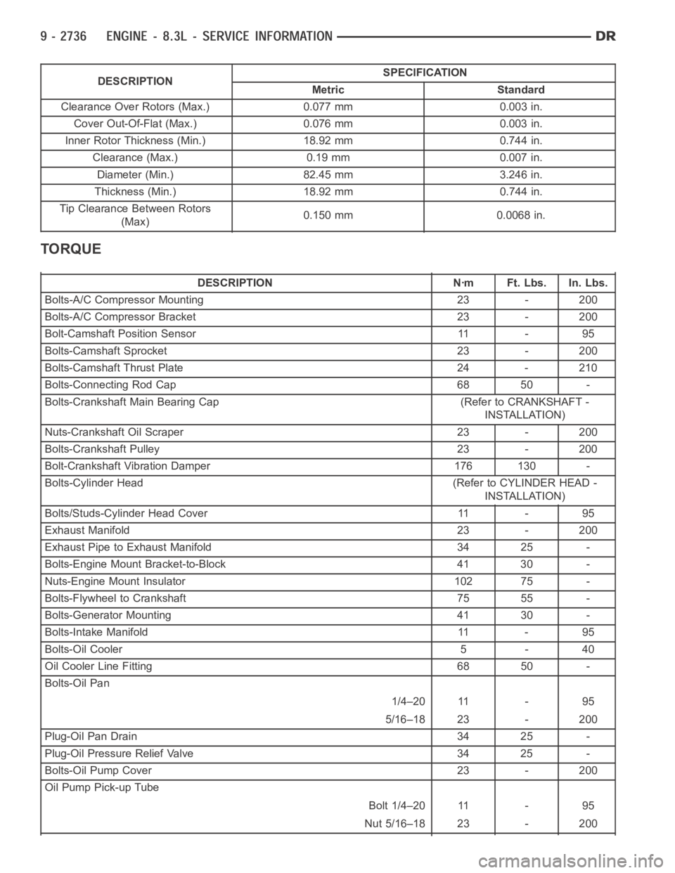
DESCRIPTIONSPECIFICATION
Metric Standard
Clearance Over Rotors (Max.) 0.077 mm 0.003 in.
Cover Out-Of-Flat (Max.) 0.076 mm 0.003 in.
Inner Rotor Thickness (Min.) 18.92 mm 0.744 in.
Clearance (Max.) 0.19 mm 0.007 in.
Diameter (Min.) 82.45 mm 3.246 in.
Thickness (Min.) 18.92 mm 0.744 in.
Tip Clearance Between Rotors
(Max)0.150 mm 0.0068 in.
TORQUE
DESCRIPTION Nꞏm Ft. Lbs. In. Lbs.
Bolts-A/C Compressor Mounting 23 - 200
Bolts-A/C Compressor Bracket 23 - 200
Bolt-Camshaft Position Sensor 11 - 95
Bolts-Camshaft Sprocket 23 - 200
Bolts-Camshaft Thrust Plate 24 - 210
Bolts-Connecting Rod Cap 68 50 -
Bolts-Crankshaft Main Bearing Cap (Refer to CRANKSHAFT -
INSTALLATION)
Nuts-Crankshaft Oil Scraper 23 - 200
Bolts-Crankshaft Pulley 23 - 200
Bolt-Crankshaft Vibration Damper 176 130 -
Bolts-Cylinder Head (Refer to CYLINDER HEAD -
INSTALLATION)
Bolts/Studs-Cylinder Head Cover 11 - 95
Exhaust Manifold 23 - 200
Exhaust Pipe to Exhaust Manifold 34 25 -
Bolts-Engine Mount Bracket-to-Block 41 30 -
Nuts-Engine Mount Insulator 102 75 -
Bolts-Flywheel to Crankshaft 75 55 -
Bolts-Generator Mounting 41 30 -
Bolts-Intake Manifold 11 - 95
Bolts-Oil Cooler 5 - 40
Oil Cooler Line Fitting 68 50 -
Bolts-Oil Pan
1/4–20 11 - 95
5/16–18 23 - 200
Plug-Oil Pan Drain 34 25 -
Plug-Oil Pressure Relief Valve 34 25 -
Bolts-Oil Pump Cover 23 - 200
Oil Pump Pick-up Tube
Bolt 1/4–20 11 - 95
Nut 5/16–18 23 - 200
Page 2052 of 5267
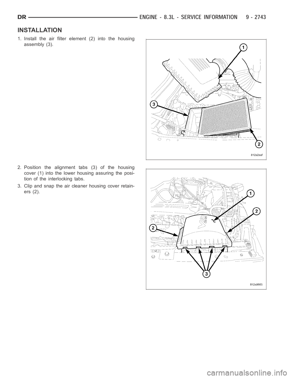
INSTALLATION
1. Install the air filter element (2) into the housing
assembly (3).
2. Position the alignment tabs (3) of the housing
cover (1) into the lower housing assuring the posi-
tion of the interlocking tabs.
3. Clip and snap the air cleaner housing cover retain-
ers (2).
Page 2055 of 5267
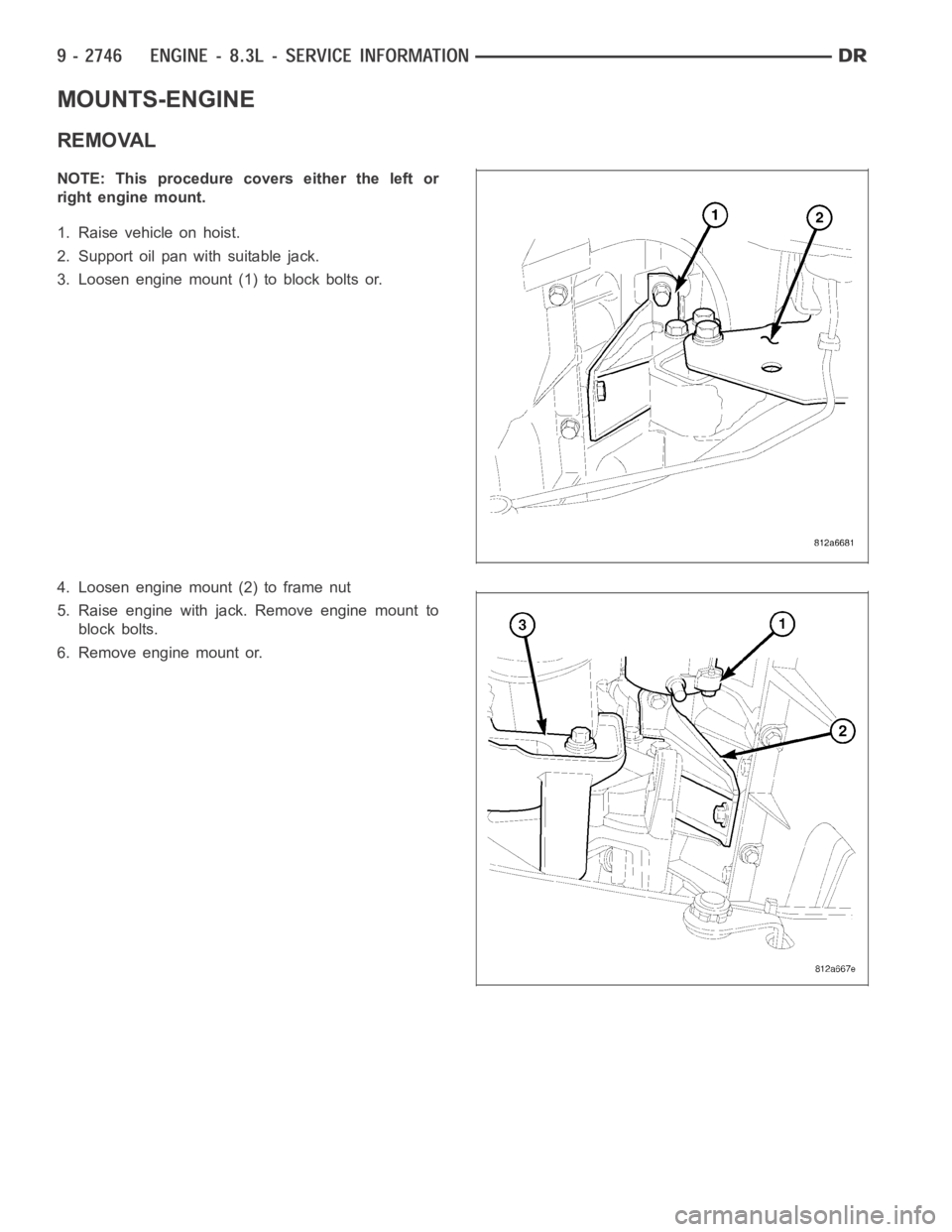
MOUNTS-ENGINE
REMOVAL
NOTE: This procedure covers either the left or
right engine mount.
1. Raise vehicle on hoist.
2. Support oil pan with suitable jack.
3. Loosen engine mount (1) to block bolts or.
4. Loosen engine mount (2) to frame nut
5. Raise engine with jack. Remove engine mount to
block bolts.
6. Remove engine mount or.