Page 2292 of 5267

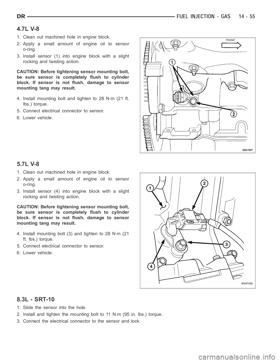
4.7L V-8
1. Clean out machined hole in engine block.
2. Apply a small amount of engine oil to sensor
o-ring.
3. Install sensor (1) into engine block with a slight
rocking and twisting action.
CAUTION: Before tightening sensor mounting bolt,
be sure sensor is completely flush to cylinder
block. If sensor is not flush, damage to sensor
mounting tang may result.
4. Install mounting bolt and tighten to 28 Nꞏm (21 ft.
lbs.) torque.
5. Connect electrical connector to sensor.
6. Lower vehicle.
5.7L V-8
1. Clean out machined hole in engine block.
2. Apply a small amount of engine oil to sensor
o-ring.
3. Install sensor (4) into engine block with a slight
rocking and twisting action.
CAUTION: Before tightening sensor mounting bolt,
be sure sensor is completely flush to cylinder
block. If sensor is not flush, damage to sensor
mounting tang may result.
4. Install mounting bolt (3) and tighten to 28 Nꞏm (21
ft. lbs.) torque.
5. Connect electrical connector to sensor.
6. Lower vehicle.
8.3L - SRT-10
1. Slide the sensor into the hole.
2. Install and tighten the mounting bolt to 11 Nꞏm (95 in. lbs.) torque.
3. Connect the electrical connector to the sensor and lock.
Page 2300 of 5267

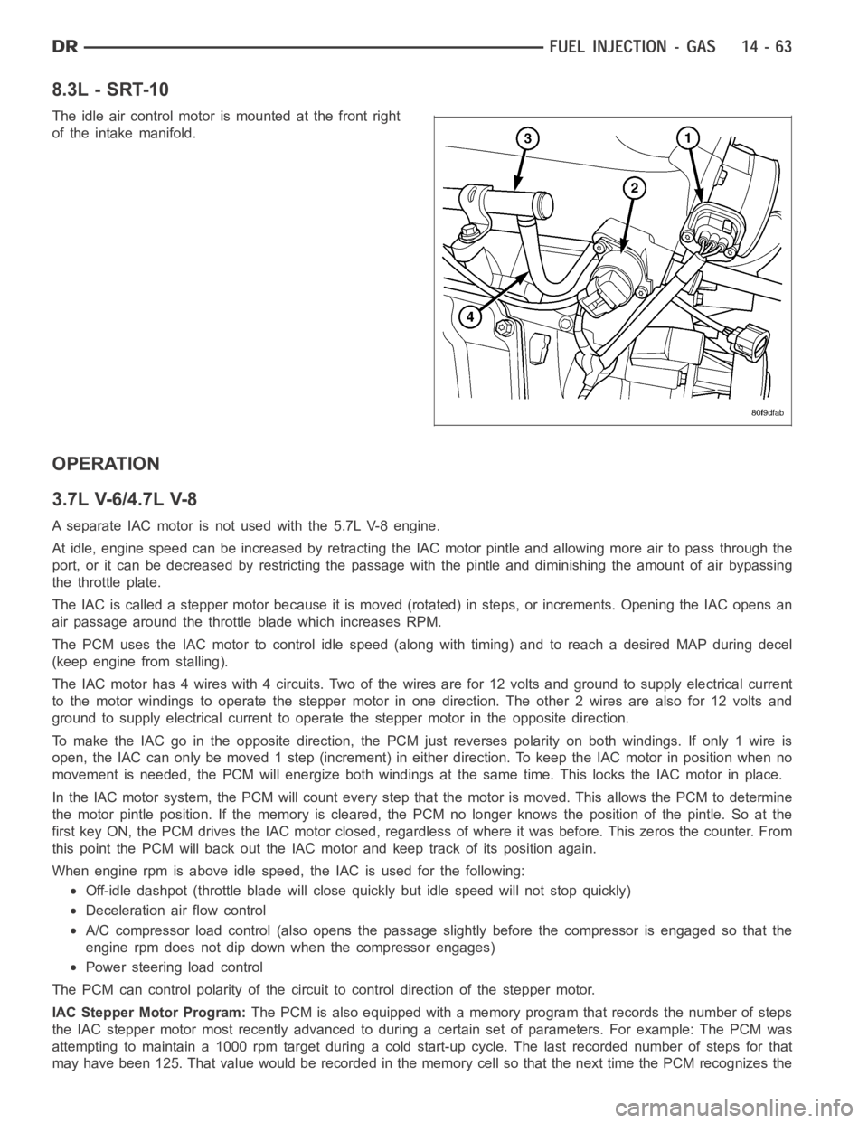
8.3L - SRT-10
The idle air control motor is mounted at the front right
of the intake manifold.
OPERATION
3.7L V-6/4.7L V-8
A separate IAC motor is not used with the 5.7L V-8 engine.
At idle, engine speed can be increased by retracting the IAC motor pintle and allowing more air to pass through the
port, or it can be decreased by restricting the passage with the pintle and diminishing the amount of air bypassing
the throttle plate.
The IAC is called a stepper motor because it is moved (rotated) in steps, or increments. Opening the IAC opens an
air passage around the throttle blade which increases RPM.
The PCM uses the IAC motor to control idle speed (along with timing) and to reach a desired MAP during decel
(keep engine from stalling).
The IAC motor has 4 wires with 4 circuits. Two of the wires are for 12 volts andground to supply electrical current
to the motor windings to operate the stepper motor in one direction. The other2wiresarealsofor12voltsand
ground to supply electrical current to operate the stepper motor in the opposite direction.
To make the IAC go in the opposite direction, the PCM just reverses polarityon both windings. If only 1 wire is
open, the IAC can only be moved 1 step (increment) in either direction. To keeptheIACmotorinpositionwhenno
movement is needed, the PCM will energize both windings at the same time. This locks the IAC motor in place.
In the IAC motor system, the PCM will count every step that the motor is moved. This allows the PCM to determine
the motor pintle position. If the memory is cleared, the PCM no longer knowsthe position of the pintle. So at the
first key ON, the PCM drives the IAC motor closed, regardless of where it wasbefore. This zeros the counter. From
this point the PCM will back out the IAC motor and keep track of its position again.
When engine rpm is above idle speed, the IAC is used for the following:
Off-idle dashpot (throttle blade will close quickly but idle speed will notstopquickly)
Deceleration air flow control
A/C compressor load control (also opens the passage slightly before the compressor is engaged so that the
engine rpm does not dip down when the compressor engages)
Power steering load control
The PCM can control polarity of the circuit to control direction of the stepper motor.
IAC Stepper Motor Program:The PCM is also equipped with a memory program that records the number of steps
the IAC stepper motor most recently advanced to during a certain set of parameters. For example: The PCM was
attempting to maintain a 1000 rpm target during a cold start-up cycle. The last recorded number of steps for that
may have been 125. That value would be recorded in the memory cell so that thenext time the PCM recognizes the
Page 2308 of 5267
REMOVAL
3.7L V-6
The intake manifold air temperature (IAT) sensor is
installed into the left side of intake manifold plenum.
1. Disconnect electrical connector from IAT sensor.
2. Clean dirt from intake manifold at sensor base.
3. Gently lift on small plastic release tab (3) and
rotate sensor about 1/4 turn counterclockwise for
removal.
4. Check condition of sensor O-ring.
Page 2309 of 5267
4.7L V-8
The intake manifold air temperature (IAT) sensor (3) is
installed into the left side of intake manifold plenum.
1. Disconnect electrical connector from IAT sensor.
2. Clean dirt from intake manifold at sensor base.
3. Gently lift on small plastic release tab (3) and
rotate sensor about 1/4 turn counterclockwise for
removal.
4. Check condition of sensor O-ring.
Page 2311 of 5267
3. Gently lift on small plastic release tab (3) and
rotate sensor about 1/4 turn counterclockwise for
removal.
4. Check condition of sensor O-ring.
INSTALLATION
3.7L V-6
The intake manifold air temperature (IAT) sensor (1) is
installed into the left side of intake manifold plenum.
1. Check condition of sensor O-ring.
2. Clean sensor mounting hole in intake manifold.
3. Position sensor into intake manifold and rotate
clockwise until past release tab (2).
4. Install electrical connector.
Page 2312 of 5267
4.7L V-8
The intake manifold air temperature (IAT) sensor (3) is
installed into the left side of intake manifold plenum.
1. Check condition of sensor O-ring.
2. Clean sensor mounting hole in intake manifold.
3. Position sensor into intake manifold and rotate
clockwise until past release tab.
4. Install electrical connector.
5.7L V-8
The intake manifold air temperature (IAT) sensor (2) is
installed into the front of the intake manifold air box
plenum.
1. Check condition of sensor O-ring.
2. Clean sensor mounting hole in intake manifold.
3. Position sensor into intake manifold and rotate
clockwise until past release tab.
4. Install electrical connector.
Page 2318 of 5267
1. Disconnect electrical connector at sensor by sliding
release lock out. Press down on lock tab for
removal.
2. Rotate sensor (3) 1/4 turn counterclockwise for
removal.
3. Check condition of sensor O-ring.
8.3 L - SRT-10
The manifold absolute pressure sensor is mounted on the drivers side of theintake manifold.
1. Disconnect the electrical connector from the MAP sensor.
2. Remove MAP sensor mounting screws.
INSTALLATION
3.7L V-6
The Manifold Absolute Pressure (MAP) sensor is
mounted into the front of the intake manifold.
Page 2320 of 5267
An O-ring (2) seals the sensor to the intake manifold.
1. Clean MAP sensor mounting hole at intake mani-
fold.
2. Check MAP sensor O-ring seal for cuts or tears.
3. Position sensor into manifold.
4. Install MAP sensor mounting bolts (screws). (Refer
to 14 - FUEL SYSTEM/FUEL DELIVERY - SPECI-
FICATIONS)
5. Connect electrical connector.
5.7L V-8
The Manifold Absolute Pressure (MAP) sensor (1) is
mounted to the front of the intake manifold air plenum
box.
1. Clean MAP sensor mounting hole at intake mani-
fold.
2. Check MAP sensor O-ring seal for cuts or tears.
3. Position sensor into manifold.
4. Rotate sensor 1/4 turn clockwise for installation.
5. Connect electrical connector.
8.3L - SRT-10
1. Install the MAP sensor to the intake manifold.
2. Install MAP sensor mounting screws and tighten mounting screws to 4 Nꞏm (35 in. lbs.).
3. Connect the electrical connector to the MAP sensor.