Page 1293 of 5267
3.(N4) FUEL LEVEL SIGNAL CIRCUIT SHORTED TO BATTERY VOLTAGE
Turn the ignition off.
Disconnect the C3 PCM harness connector.
Ignition on, engine not running.
Measure the voltage on the (N4) Fuel Level Signal circuit in the Fuel
Pump Module harness connector.
Is the voltage above 0 volts?
Ye s>>
Repair the short to battery voltage in the (N4) Fuel Level
Signal circuit.
Perform the POWERTRAIN VERIFICATION TEST. (Refer to
9 - ENGINE - STANDARD PROCEDURE)
No>>
Go To 4
4.(N4) FUEL LEVEL SIGNAL CIRCUIT OPEN
Turn the ignition off.
Measure the resistance of the (N4) Fuel Level Signal circuit from the
Fuel Pump Module harness connector to the PCM harness connector.
Is the resistance below 5.0 ohms?
Ye s>>
Go To 5
No>>
Repair the open in the (N4) Fuel Level Signal circuit.
Perform the POWERTRAIN VERIFICATION TEST. (Refer to
9 - ENGINE - STANDARD PROCEDURE)
Page 1299 of 5267
When Monitored:
At power-up and battery voltage greater than 11.5 volts.
Set Condition:
The PCM senses a short to ground or battery voltage on any of the four Idle AirControl (IAC) driver circuits
for 100 ms while the IAC motor is active.
Possible Causes
(K40) IAC #1 DRIVER CIRCUIT SHORTED TO (K60) #2, (K39) #3, OR (K59) #4 IAC DRIVER CIRCUITS
(K60) IAC #2 DRIVER CIRCUIT SHORTED TO (K39) IAC #3 OR (K59) IAC #4
(K39) IAC #3 DRIVER CIRCUIT SHORTED TO (K59) IAC #4 DRIVER CIRCUIT
IAC DRIVER CIRCUIT SHORTED TO VOLTAGE
IAC DRIVER CIRCUIT SHORTED TO GROUND
IAC MOTOR
PCM
Always perform the Pre-Diagnostic Troubleshooting procedure before proceeding. (Refer to 9 - ENGINE -
DIAGNOSIS AND TESTING)
1.GOOD TRIP EQUAL TO ZERO
Ignition on, engine not running.
With the scan tool, read DTCs and record the related Freeze Frame data.
Is the Good Trip Counter displayed and equal to zero?
Ye s>>
Go To 2
No>>
Refer to the INTERMITTENT CONDITIONSymptom (Diagnostic Procedure).
Perform POWERTRAIN VERIFICATION TEST. (Refer to 9 - ENGINE - STANDARD PROCEDURE)
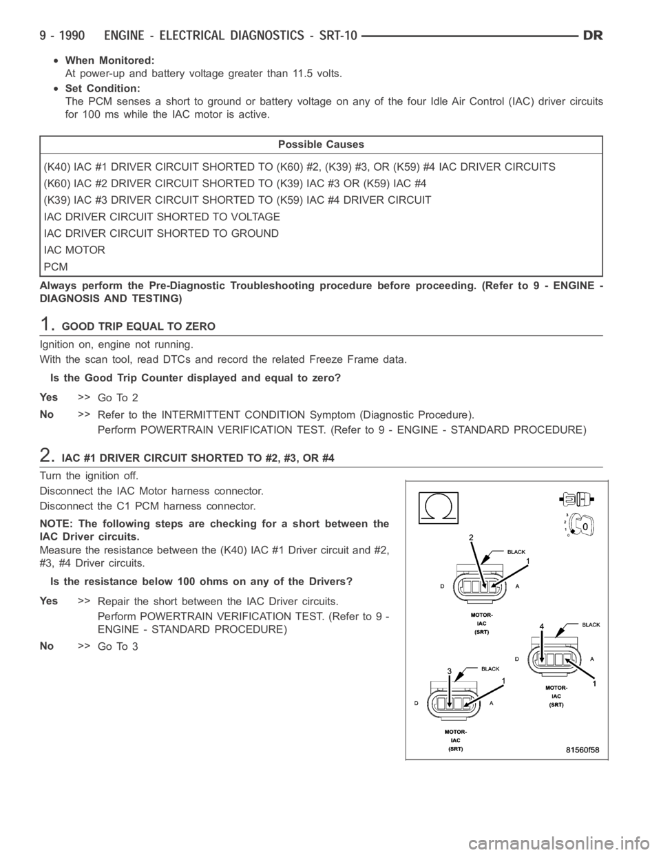
2.IAC #1 DRIVER CIRCUIT SHORTED TO #2, #3, OR #4
Turn the ignition off.
Disconnect the IAC Motor harness connector.
Disconnect the C1 PCM harness connector.
NOTE: The following steps are checking for a short between the
IAC Driver circuits.
Measure the resistance between the (K40) IAC #1 Driver circuit and #2,
#3, #4 Driver circuits.
Istheresistancebelow100ohmsonanyoftheDrivers?
Ye s>>
Repair the short between the IAC Driver circuits.
Perform POWERTRAIN VERIFICATION TEST. (Refer to 9 -
ENGINE - STANDARD PROCEDURE)
No>>
Go To 3
Page 1310 of 5267
When Monitored:
With the ignition on and battery voltage above 10.4 volts.
Set Condition:
The oil pressure sensor signal at PCM goes above 4.9 volts. One Trip Fault.
Possible Causes
OIL PRESSURE SENSOR
(G6) OIL PRESSURE SIGNAL CIRCUIT SHORTED TO BATTERY VOLTAGE
(G6) OIL PRESSURE SIGNAL CIRCUIT OPEN
(K900) SENSOR GROUND CIRCUIT OPEN
PCM
Always perform the Pre-Diagnostic Troubleshooting procedure before proceeding. (Refer to 9 - ENGINE -
DIAGNOSIS AND TESTING)
1.OIL PRESSURE SENSOR VOLTAGE ABOVE 4.8 VOLTS
Ignition on, engine not running.
With the scan tool in Sensors, read the Oil Pressure Sensor voltage.
Is the Oil Pressure Sensor voltage above 4.8 volts?
Ye s>>
Go To 2
No>>
Refer to the INTERMITTENT CONDITION Diagnostic Procedure.
Perform POWERTRAIN VERIFICATION TEST. (Refer to 9 - ENGINE - STANDARD PROCEDURE)
2.OIL PRESSURE SENSOR
Turn the ignition off.
Disconnect the Oil Pressure Sensor harness connector.
Ignition on, engine not running.
Connect a jumper wire between the (G60) Oil Pressure Signal circuit and (K900) Sensor ground circuit at the Sen-
sor harness connector.
With the scan tool in Sensors, read the Oil Pressure Sensor voltage.
Is the voltage below 1.0 volt?
Ye s>>
Replace the Oil Pressure Sensor.
Perform POWERTRAIN VERIFICATION TEST. (Refer to 9 - ENGINE - STANDARD PROCEDURE)
No>>
Go To 3
NOTE: Remove the jumper wire before continuing.
3.(G6) OIL PRESSURE SIGNAL CIRCUIT SHORTED TO BATTERY VOLTAGE
Turn the ignition off.
Disconnect the PCM harness connectors.
Ignition on, engine not running.
Using a 12-volt test light connected to ground, probe the (G6) Oil PressureSignal circuit.
Is the test light brightly illuminated?
Ye s>>
Repair the short to voltage in the (G6) Oil Pressure Signal circuit.
Perform POWERTRAIN VERIFICATION TEST. (Refer to 9 - ENGINE - STANDARD PROCEDURE)
No>>
Go To 4
Page 1318 of 5267
When Monitored:
With the ignition on. Battery voltage greater than 10 volts. A/C Switch on.
Set Condition:
An open or shorted condition is detected in the A/C clutch relay control circuit. One Trip Fault. Three good trips
to turn off the MIL.
Possible Causes
INTERNAL FUSED IGNITION SWITCH OUTPUT CIRCUIT
INTERNAL FUSED B+ CIRCUIT
(C13) A/C CLUTCH RELAY CONTROL CIRCUIT OPEN
(C13) A/C CLUTCH RELAY CONTROL CIRCUIT SHORTED TO GROUND
A/CCLUTCHRELAY
PCM
Always perform the Pre-Diagnostic Troubleshooting procedure before proceeding. (Refer to 9 - ENGINE -
DIAGNOSIS AND TESTING).
Diagnostic Test
1.A/C CLUTCH RELAY OPERATION
Ignition on, engine not running.
With a scan tool, actuate the A/C Clutch Relay.
Is the A/C Clutch Relay operating?
Ye s>>
Refer to the INTERMITTENT CONDITION Diagnostic Procedure.
Perform the POWERTRAIN VERIFICATION TEST. (Refer to 9 - ENGINE - STANDARD PROCEDURE)
No>>
Go To 2
2.A/C CLUTCH RELAY RESISTANCE
Turn the ignition off.
Remove the A/C Clutch Relay from the IPM.
Measure the resistance of the A/C Clutch Relay Coil.
Is the resistance between 60 to 80 ohms?
Ye s>>
Go To 3
No>>
Replace the A/C Clutch Relay.
Perform the POWERTRAIN VERIFICATION TEST. (Refer to 9 - ENGINE - STANDARD PROCEDURE)
Page 1332 of 5267
When Monitored:
With the ignition on. Battery voltage greater than 10 volts.
Set Condition:
A shorted condition is detected in the ASD control circuit. One Trip Fault.Three good trips to turn off the MIL.
Possible Causes
(K342) ASD CONTROL OUTPUT CIRCUIT SHORTED TO GROUND
FUEL INJECTOR
IGNITION COIL
PCM
TIPM
Always perform the Pre-Diagnostic Troubleshooting procedure before proceeding. (Refer to 9 - ENGINE -
DIAGNOSIS AND TESTING).
Diagnostic Test
1.ASD OPERATION
Ignition on, engine not running.
With a scan tool under the ECM Actuators, actuate the ASD Circuit.
Are the Injectors actuating?
Ye s>>
Refer to the INTERMITTENT CONDITION Diagnostic Procedure.
Perform the POWERTRAIN VERIFICATION TEST. (Refer to 9 - ENGINE - STANDARD PROCEDURE)
No>>
Go To 2
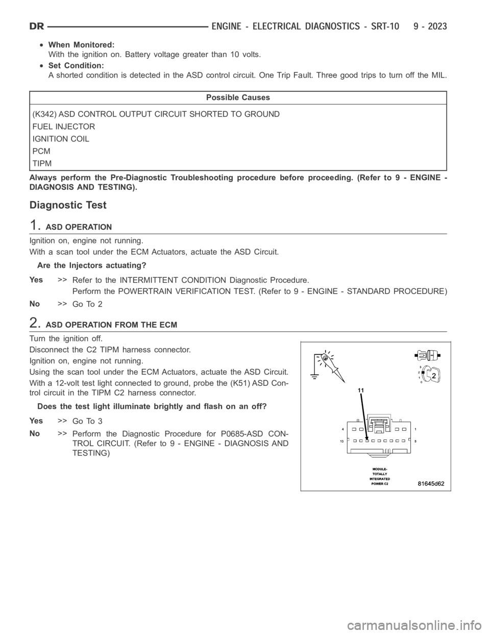
2.ASD OPERATION FROM THE ECM
Turn the ignition off.
Disconnect the C2 TIPM harness connector.
Ignition on, engine not running.
Using the scan tool under the ECM Actuators, actuate the ASD Circuit.
With a 12-volt test light connected to ground, probe the (K51) ASD Con-
trol circuit in the TIPM C2 harness connector.
Does the test light illuminate brightly and flash on an off?
Ye s>>
Go To 3
No>>
Perform the Diagnostic Procedure for P0685-ASD CON-
TROL CIRCUIT. (Refer to 9 - ENGINE - DIAGNOSIS AND
TESTING)
Page 1336 of 5267
When Monitored:
With the ignition on. Battery voltage greater than 10 volts.
Set Condition:
A shorted condition is detected in the ASD control circuit. One Trip Fault.Three good trips to turn off the MIL.
Possible Causes
(K342) ASD CONTROL OUTPUT CIRCUIT SHORTED TO VOLTAGE
FUEL INJECTOR
IGNITION COIL
ECM
TIPM
Always perform the Pre-Diagnostic Troubleshooting procedure before proceeding. (Refer to 9 - ENGINE -
DIAGNOSIS AND TESTING).
Diagnostic Test
1.ACTIVE DTC
Ignition on, engine not running.
With a scan tool, read DTCs.
Is the DTC active at this time?
Ye s>>
Go To 2
No>>
Refer to the INTERMITTENT CONDITION Diagnostic Procedure.
Perform the POWERTRAIN VERIFICATION TEST. (Refer to 9 - ENGINE - STANDARD PROCEDURE)
2.ASD OPERATION FROM THE ECM
Turn the ignition off.
Disconnect the C2 TIPM harness connector.
Ignition on, engine not running.
Using the scan tool under the ECM Actuators, actuate the ASD Circuit.
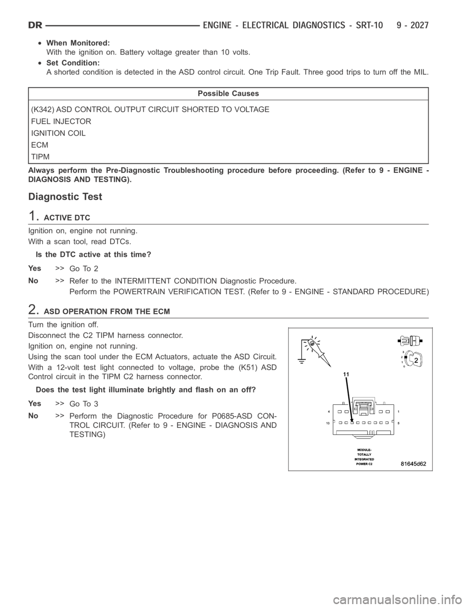
With a 12-volt test light connected to voltage, probe the (K51) ASD
Control circuit in the TIPM C2 harness connector.
Does the test light illuminate brightly and flash on an off?
Ye s>>
Go To 3
No>>
Perform the Diagnostic Procedure for P0685-ASD CON-
TROL CIRCUIT. (Refer to 9 - ENGINE - DIAGNOSIS AND
TESTING)
Page 1340 of 5267
When Monitored:
With the ignition on. Battery voltage greater than 10 volts.
Set Condition:
An open condition is detected in the ASD control circuit. One Trip Fault. Three good trips to turn off the MIL.
Possible Causes
(K342) ASD CONTROL OUTPUT CIRCUIT OPEN
FUEL INJECTOR
IGNITION COIL
PCM
TIPM
Always perform the Pre-Diagnostic Troubleshooting procedure before proceeding. (Refer to 9 - ENGINE -
DIAGNOSIS AND TESTING).
Diagnostic Test
1.ACTIVE DTC
Ignition on, engine not running.
With a scan tool, read DTCs.
Is the DTC active at this time?
Ye s>>
Go To 2
No>>
Refer to the INTERMITTENT CONDITION Diagnostic Procedure.
Perform the POWERTRAIN VERIFICATION TEST. (Refer to 9 - ENGINE - STANDARD PROCEDURE)
2.ASD OPERATION FROM THE PCM
Turn the ignition off.
Disconnect the C2 TIPM harness connector.
Ignition on, engine not running.
Using the scan tool under the PCM Actuators, actuate the ASD Circuit.
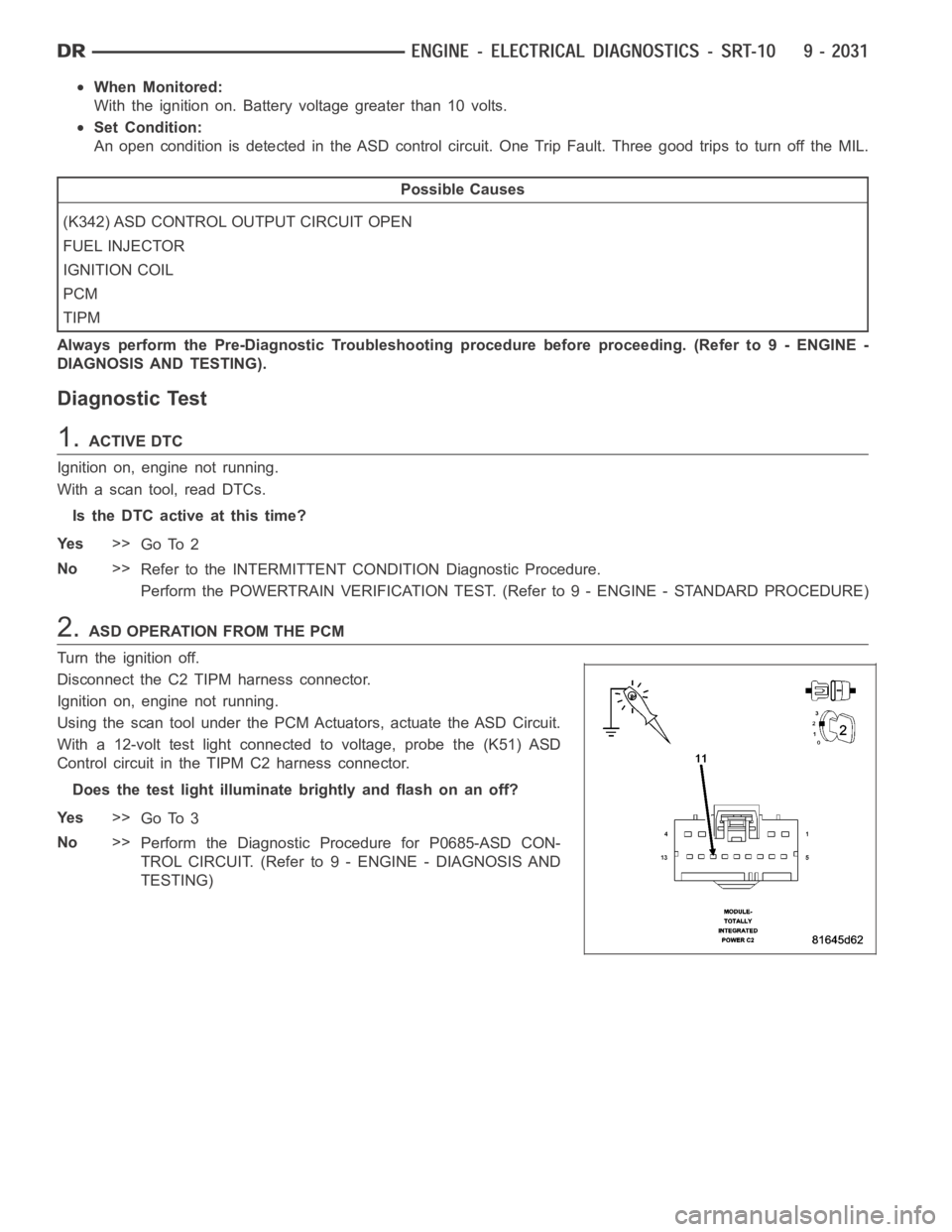
With a 12-volt test light connected to voltage, probe the (K51) ASD
Control circuit in the TIPM C2 harness connector.
Does the test light illuminate brightly and flash on an off?
Ye s>>
Go To 3
No>>
Perform the Diagnostic Procedure for P0685-ASD CON-
TROL CIRCUIT. (Refer to 9 - ENGINE - DIAGNOSIS AND
TESTING)
Page 1344 of 5267
When Monitored:
With the ignition on. Battery voltage greater than 10 volts.
Set Condition:
An overcurrent condition is detected in the ASD control circuit. One Trip Fault. Three good trips to turn off the
MIL.
Possible Causes
(K342) ASD CONTROL OUTPUT CIRCUIT EXCESSIVE RESISTANCE
FUEL INJECTOR
IGNITION COIL
PCM
TIPM
Always perform the Pre-Diagnostic Troubleshooting procedure before proceeding. (Refer to 9 - ENGINE -
DIAGNOSIS AND TESTING).
Diagnostic Test
1.ACTIVE DTC
Ignition on, engine not running.
With a scan tool, read DTCs.
Is the DTC active at this time?
Ye s>>
Go To 2
No>>
Refer to the INTERMITTENT CONDITION Diagnostic Procedure.
Perform the POWERTRAIN VERIFICATION TEST. (Refer to 9 - ENGINE - STANDARD PROCEDURE)
2.ASD OPERATION FROM THE PCM
Turn the ignition off.
Disconnect the C2 TIPM harness connector.
Ignition on, engine not running.
Using the scan tool under the PCM Actuators, actuate the ASD Circuit.
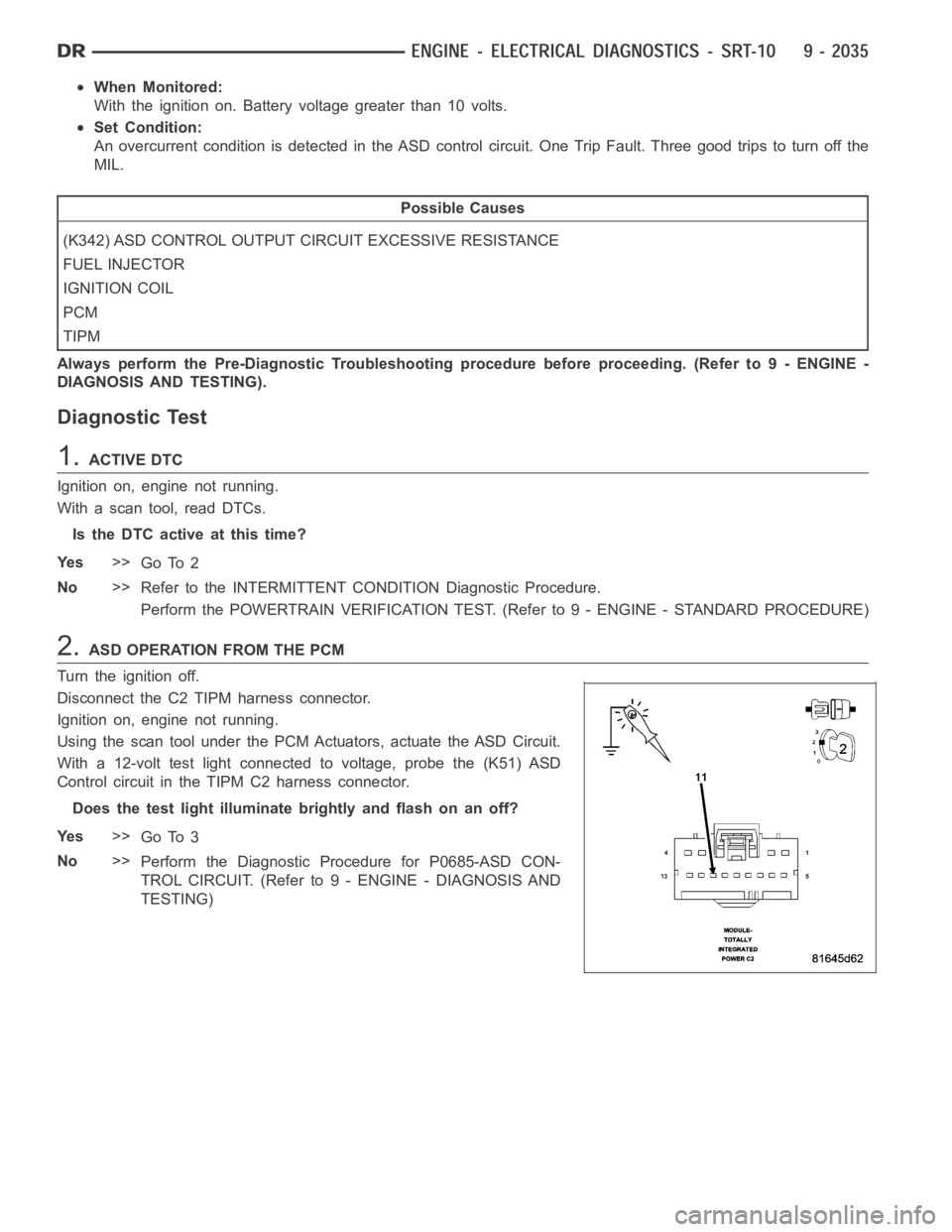
With a 12-volt test light connected to voltage, probe the (K51) ASD
Control circuit in the TIPM C2 harness connector.
Does the test light illuminate brightly and flash on an off?
Ye s>>
Go To 3
No>>
Perform the Diagnostic Procedure for P0685-ASD CON-
TROL CIRCUIT. (Refer to 9 - ENGINE - DIAGNOSIS AND
TESTING)