2006 DODGE RAM SRT-10 battery
[x] Cancel search: batteryPage 1239 of 5267
When Monitored:
During engine cranking and with the engine running. Battery voltage greater than 10 volts.
Set Condition:
At least 5 seconds or 2.5 engine revolutions have elapsed with crankshaft position sensor signals present but
no camshaft position sensor signal. One Trip Fault. Three good trips to turnofftheMIL.
Possible Causes
(F855) 5-VOLT SUPPLY CIRCUIT SHORTED TO BATTERY VOLTAGE
(F855) 5-VOLT SUPPLY CIRCUIT OPEN
(F855) 5-VOLT SUPPLY CIRCUIT SHORTED TO GROUND
(K44) CMP SIGNAL CIRCUIT SHORTED TO BATTERY VOLTAGE
(K44) CMP SIGNAL CIRCUIT OPEN
(K44) CMP SIGNAL CIRCUIT SHORTED GROUND
(K44) CMP SIGNAL SHORTED TO THE (F855) 5-VOLT SUPPLY CIRCUIT
(K900) SENSOR GROUND CIRCUIT OPEN
CAMSHAFT POSITION SENSOR
CRANKSHAFT POSITION SENSOR
PCM
Always perform the Pre-Diagnostic Troubleshooting procedure before proceeding. (Refer to 9 - ENGINE -
DIAGNOSIS AND TESTING).
Diagnostic Test
1.ACTIVE DTC
Crank the engine.
Ignition on, engine not running.
With a scan tool read the DTCs.
Is the DTC active at this time?
Ye s>>
Go To 2
No>>
Go To 14
2.(F855) 5-VOLT SUPPLY CIRCUIT
Turn the ignition off.
Disconnect the CMP Sensor harness connector.
Ignition on, engine not running.
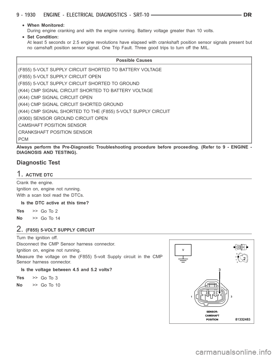
Measure the voltage on the (F855) 5-volt Supply circuit in the CMP
Sensor harness connector.
Is the voltage between 4.5 and 5.2 volts?
Ye s>>
Go To 3
No>>
Go To 10
Page 1241 of 5267
6.CAMSHAFT POSITION SENSOR
NOTE: Inspect the Camshaft sprocket for damage per the Service Information. If a problem is found repair
as necessary.
If there are no possible causes remaining, view repair.
Repair
Replace the Camshaft Position Sensor.
Perform the POWERTRAIN VERIFICATION TEST. (Refer to 9 - ENGINE - STANDARD PROCEDURE)
7.(K44) CMP SIGNAL CIRCUIT SHORTED TO BATTERY VOLTAGE
Turn the ignition off.
Disconnect the PCM harness connector.
Ignition on, engine not running.
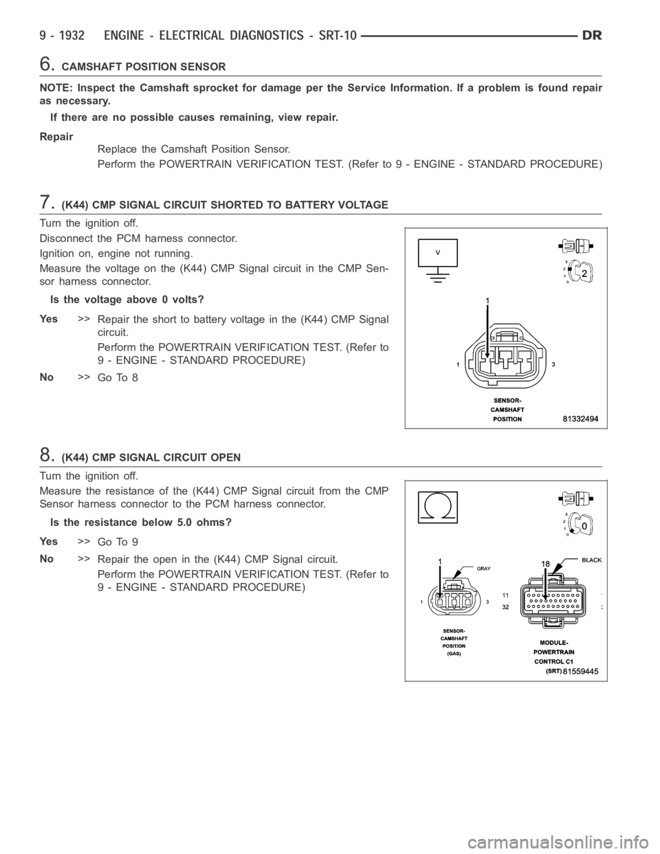
Measure the voltage on the (K44) CMP Signal circuit in the CMP Sen-
sor harness connector.
Is the voltage above 0 volts?
Ye s>>
Repair the short to battery voltage in the (K44) CMP Signal
circuit.
Perform the POWERTRAIN VERIFICATION TEST. (Refer to
9 - ENGINE - STANDARD PROCEDURE)
No>>
Go To 8
8.(K44) CMP SIGNAL CIRCUIT OPEN
Turn the ignition off.
Measure the resistance of the (K44) CMP Signal circuit from the CMP
Sensor harness connector to the PCM harness connector.
Is the resistance below 5.0 ohms?
Ye s>>
Go To 9
No>>
Repair the open in the (K44) CMP Signal circuit.
Perform the POWERTRAIN VERIFICATION TEST. (Refer to
9 - ENGINE - STANDARD PROCEDURE)
Page 1242 of 5267
9.(K44) CMP SIGNAL CIRCUIT SHORTED TO GROUND
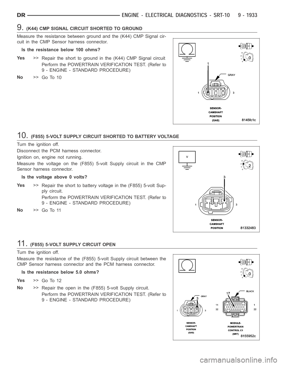
Measure the resistance between ground and the (K44) CMP Signal cir-
cuit in the CMP Sensor harness connector.
Istheresistancebelow100ohms?
Ye s>>
Repair the short to ground in the (K44) CMP Signal circuit
Perform the POWERTRAIN VERIFICATION TEST. (Refer to
9 - ENGINE - STANDARD PROCEDURE)
No>>
Go To 10
10.(F855) 5-VOLT SUPPLY CIRCUIT SHORTED TO BATTERY VOLTAGE
Turn the ignition off.
Disconnect the PCM harness connector.
Ignition on, engine not running.
Measure the voltage on the (F855) 5-volt Supply circuit in the CMP
Sensor harness connector.
Is the voltage above 0 volts?
Ye s>>
Repair the short to battery voltage in the (F855) 5-volt Sup-
ply circuit.
Perform the POWERTRAIN VERIFICATION TEST. (Refer to
9 - ENGINE - STANDARD PROCEDURE)
No>>
Go To 11
11 .(F855) 5-VOLT SUPPLY CIRCUIT OPEN
Turn the ignition off.
Measure the resistance of the (F855) 5-volt Supply circuit between the
CMP Sensor harness connector and the PCM harness connector.
Is the resistance below 5.0 ohms?
Ye s>>
Go To 12
No>>
Repair the open in the (F855) 5-volt Supply circuit.
Perform the POWERTRAIN VERIFICATION TEST. (Refer to
9 - ENGINE - STANDARD PROCEDURE)
Page 1246 of 5267
When Monitored:
With battery voltage greater than 8 volts during engine cranking or greater than 12 volts with engine running,
engine rpm less than 2016, and none of the coils in dwell when checked.
Set Condition:
Peak current is not achieved with battery based dwell plus 1.5 ms of diagnostic offset. It takes less than 3
seconds during cranking or up to 6 seconds while running to set.
Possible Causes
(K343) ASD RELAY OUTPUT CIRCUIT
IGNITION COIL
(K17) IGNITION COIL NO.2 CONTROL CIRCUIT OPEN
(K17) IGNITION COIL NO.2 CONTROL CIRCUIT SHORTED TO GROUND
PCM
Always perform the Pre-Diagnostic Troubleshooting procedure before proceeding. (Refer to 9 - ENGINE -
DIAGNOSIS AND TESTING)
1.GOOD TRIP EQUAL TO ZERO
Ignition on, engine not running.
With the scan tool, read DTCs and record the related Freeze Frame data.
Is the Good Trip Counter displayed and equal to zero?
Ye s>>
Go To 2
No>>
Refer to the INTERMITTENT CONDTION Diagnostic Procedure.
Perform POWERTRAIN VERIFICATION TEST. (Refer to 9 - ENGINE - STANDARD PROCEDURE)
2.(K343) ASD RELAY OUTPUT CIRCUIT
Turn the ignition off.
Disconnect the Ignition coil harness connector.
Ignition on, engine not running.
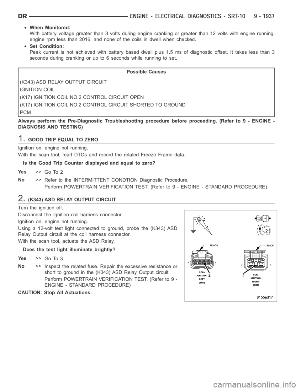
Using a 12-volt test light connected to ground, probe the (K343) ASD
Relay Output circuit at the coil harness connector.
With the scan tool, actuate the ASD Relay.
Does the test light illuminate brightly?
Ye s>>
Go To 3
No>>
Inspect the related fuse. Repair the excessive resistance or
short to ground in the (K343) ASD Relay Output circuit.
Perform POWERTRAIN VERIFICATION TEST. (Refer to 9 -
ENGINE - STANDARD PROCEDURE)
CAUTION: Stop All Actuations.
Page 1250 of 5267
When Monitored:
With battery voltage greater than 8 volts during engine cranking or greater than 12 volts with engine running,
engine rpm less than 2016, and none of the coils in dwell when checked.
Set Condition:
Peak current is not achieved with battery based dwell plus 1.5 ms of diagnostic offset. It takes less than 3
seconds during cranking or up to 6 seconds while running to set.
Possible Causes
(K343) ASD RELAY OUTPUT CIRCUIT
IGNITION COIL
(K18) IGNITION COIL CONTROL NO.3 CIRCUIT OPEN
(K18) IGNITION COIL CONTROL NO.3 CIRCUIT SHORTED TO GROUND
PCM
Always perform the Pre-Diagnostic Troubleshooting procedure before proceeding. (Refer to 9 - ENGINE -
DIAGNOSIS AND TESTING)
1.GOOD TRIP EQUAL TO ZERO
Ignition on, engine not running.
With the scan tool, read DTCs and record the related Freeze Frame data.
Is the Good Trip Counter displayed and equal to zero?
Ye s>>
Go To 2
No>>
Refer to the INTERMITTENT CONDTION Diagnostic Procedure.
Perform POWERTRAIN VERIFICATION TEST. (Refer to 9 - ENGINE - STANDARD PROCEDURE)
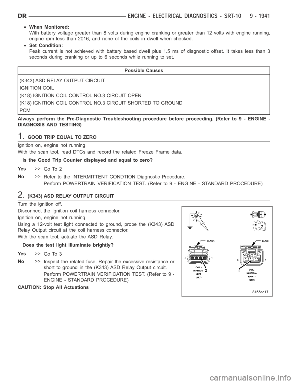
2.(K343) ASD RELAY OUTPUT CIRCUIT
Turn the ignition off.
Disconnect the Ignition coil harness connector.
Ignition on, engine not running.
Using a 12-volt test light connected to ground, probe the (K343) ASD
Relay Output circuit at the coil harness connector.
With the scan tool, actuate the ASD Relay.
Does the test light illuminate brightly?
Ye s>>
Go To 3
No>>
Inspect the related fuse. Repair the excessive resistance or
short to ground in the (K343) ASD Relay Output circuit.
Perform POWERTRAIN VERIFICATION TEST. (Refer to 9 -
ENGINE - STANDARD PROCEDURE)
CAUTION: Stop All Actuations
Page 1254 of 5267
When Monitored:
With battery voltage greater than 8 volts during engine cranking or greater than 12 volts with engine running,
engine rpm less than 2016, and none of the coils in dwell when checked.
Set Condition:
Peak current is not achieved with battery based dwell plus 1.5 ms of diagnostic offset. It takes less than 3
seconds during cranking or up to 6 seconds while running to set.
Possible Causes
(K343) ASD RELAY OUTPUT CIRCUIT
IGNITION COIL
(K133) IGNITION COIL CONTROL NO.4 CIRCUIT OPEN
(K133) IGNITION COIL CONTROL NO.4 CIRCUIT SHORTED TO GROUND
PCM
Always perform the Pre-Diagnostic Troubleshooting procedure before proceeding. (Refer to 9 - ENGINE -
DIAGNOSIS AND TESTING)
1.GOOD TRIP EQUAL TO ZERO
Ignition on, engine not running.
With the scan tool, read DTCs and record the related Freeze Frame data.
Is the Good Trip Counter displayed and equal to zero?
Ye s>>
Go To 2
No>>
Refer to the INTERMITTENT CONDTION Diagnostic Procedure.
Perform POWERTRAIN VERIFICATION TEST. (Refer to 9 - ENGINE - STANDARD PROCEDURE)
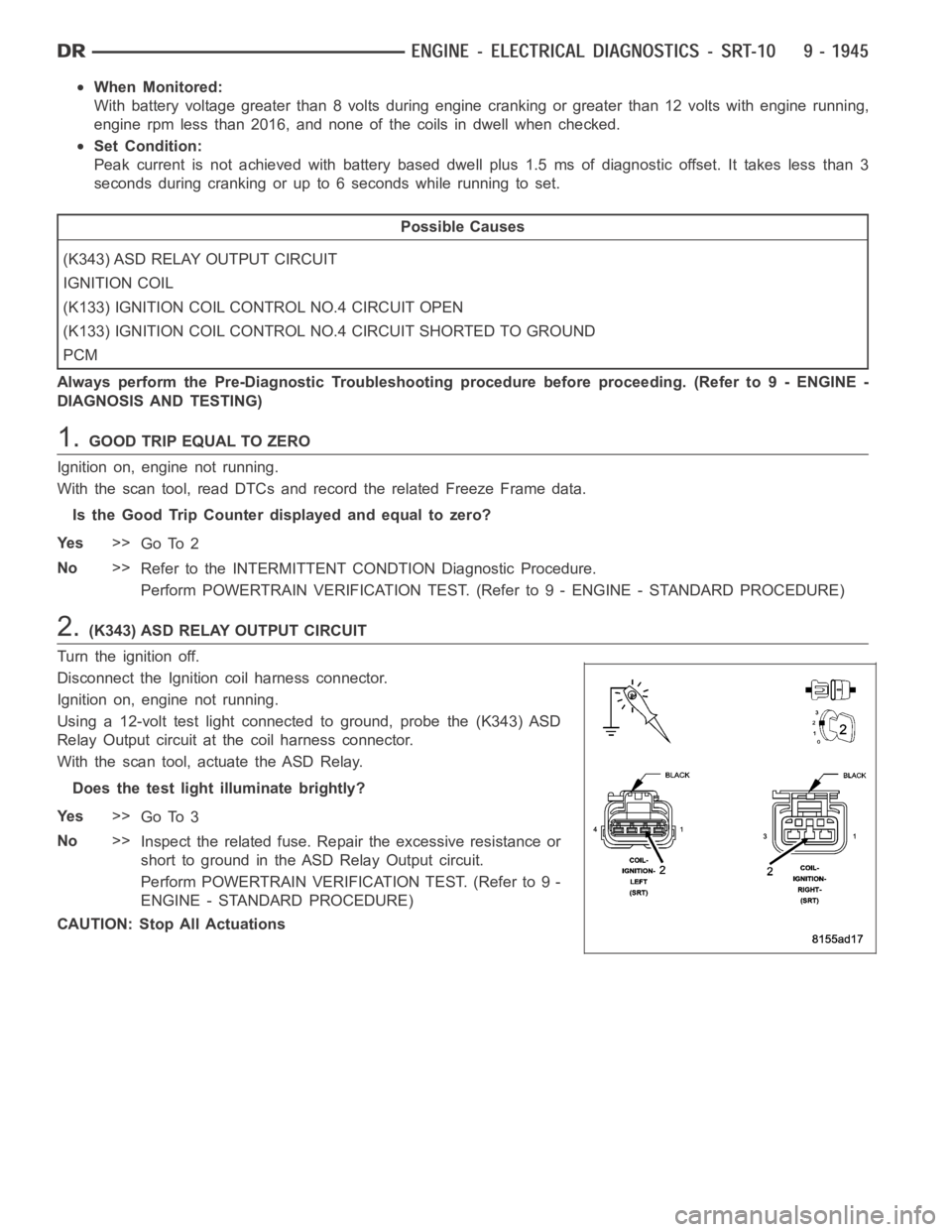
2.(K343) ASD RELAY OUTPUT CIRCUIT
Turn the ignition off.
Disconnect the Ignition coil harness connector.
Ignition on, engine not running.
Using a 12-volt test light connected to ground, probe the (K343) ASD
Relay Output circuit at the coil harness connector.
With the scan tool, actuate the ASD Relay.
Does the test light illuminate brightly?
Ye s>>
Go To 3
No>>
Inspect the related fuse. Repair the excessive resistance or
short to ground in the ASD Relay Output circuit.
Perform POWERTRAIN VERIFICATION TEST. (Refer to 9 -
ENGINE - STANDARD PROCEDURE)
CAUTION: Stop All Actuations
Page 1258 of 5267
When Monitored:
With battery voltage greater than 8 volts during engine cranking or greater than 12 volts with engine running,
engine rpm less than 2016, and none of the coils in dwell when checked.
Set Condition:
Peak current is not achieved with battery based dwell plus 1.5 ms of diagnostic offset. It takes less than 3
seconds during cranking or up to 6 seconds while running to set.
Possible Causes
(K343) ASD RELAY OUTPUT CIRCUIT
IGNITION COIL
(K134) IGNITION COIL CONTROL NO.5 CIRCUIT OPEN
(K134) IGNITION COIL CONTROL NO.5 CIRCUIT SHORTED TO GROUND
PCM
Always perform the Pre-Diagnostic Troubleshooting procedure before proceeding. (Refer to 9 - ENGINE -
DIAGNOSIS AND TESTING)
1.GOOD TRIP EQUAL TO ZERO
Ignition on, engine not running.
With the scan tool, read DTCs and record the related Freeze Frame data.
Is the Good Trip Counter displayed and equal to zero?
Ye s>>
Go To 2
No>>
Refer to the INTERMITTENT CONDTION Diagnostic Procedure.
Perform POWERTRAIN VERIFICATION TEST. (Refer to 9 - ENGINE - STANDARD PROCEDURE)
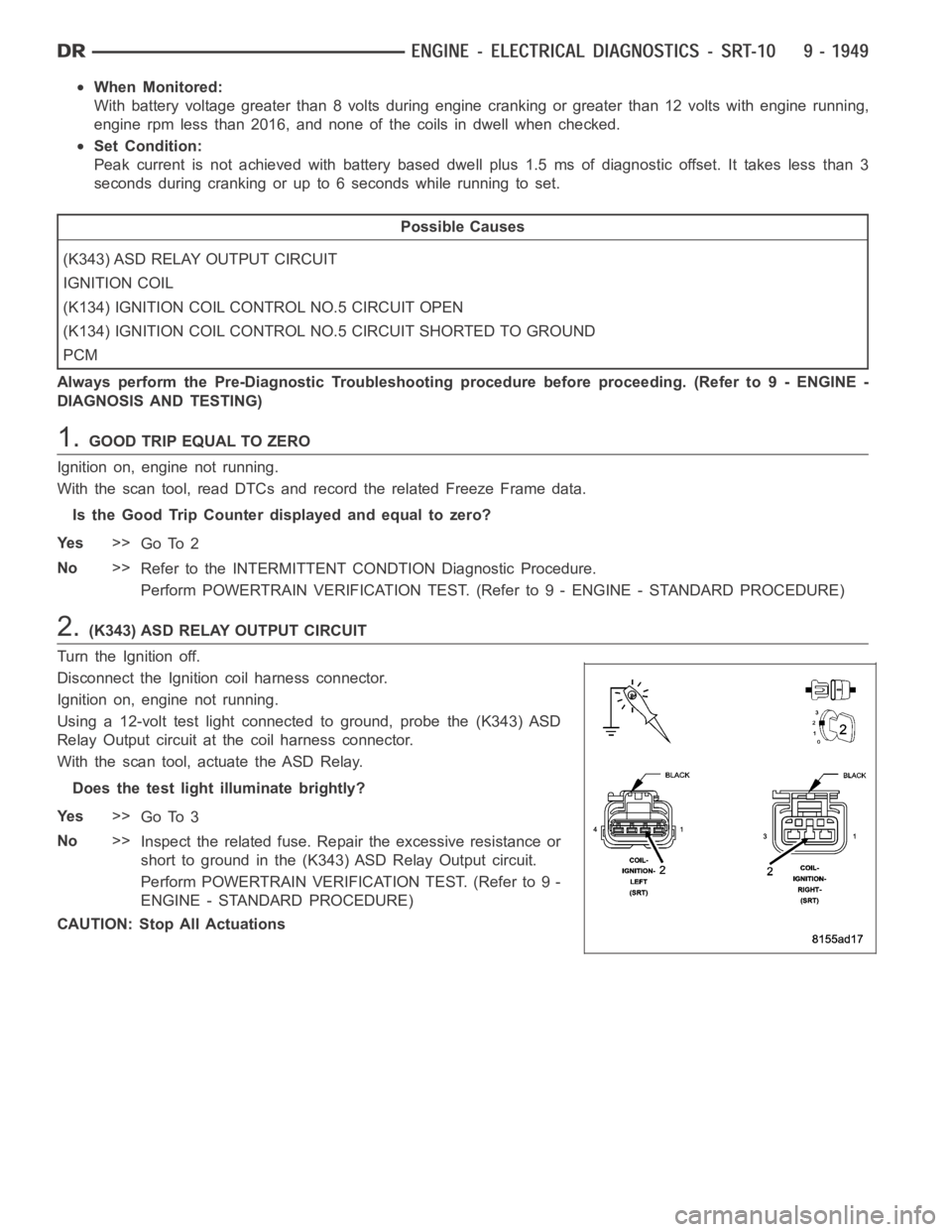
2.(K343) ASD RELAY OUTPUT CIRCUIT
Turn the Ignition off.
Disconnect the Ignition coil harness connector.
Ignition on, engine not running.
Using a 12-volt test light connected to ground, probe the (K343) ASD
Relay Output circuit at the coil harness connector.
With the scan tool, actuate the ASD Relay.
Does the test light illuminate brightly?
Ye s>>
Go To 3
No>>
Inspect the related fuse. Repair the excessive resistance or
short to ground in the (K343) ASD Relay Output circuit.
Perform POWERTRAIN VERIFICATION TEST. (Refer to 9 -
ENGINE - STANDARD PROCEDURE)
CAUTION: Stop All Actuations
Page 1272 of 5267
When Monitored:
Immediately after a cold start, with battery/ambient temperature between 40° F and 90° F and coolant tem-
perature within 10° F of battery/ambient.
Set Condition:
If there is a leak larger than 0.040
and smaller than 0.080in the evaporative system.
Possible Causes
EVAP PURGE SYSTEM LEAK
GAS CAP
EVAP PURGE SOLENOID
LEAK DETECTION PUMP
Always perform the Pre-Diagnostic Troubleshooting procedure before proceeding. (Refer to 9 - ENGINE -
DIAGNOSIS AND TESTING).
Diagnostic Test
1.VEHICLE HISTORY AND SERVICE BULLETIN INVESTIGATION
Ignition on, engine not running.
With a scan tool, read DTCs and record the related Freeze Frame data if any DTC(s) are present.
Whether or not any DTC(s) are present you will want to check the following items which may assist in repairing the
customer’s complaint successfully.
Check the vehicles repair history.
If the vehicle has a repair history that pertains to the customer’s currentcomplaint, review the repair.
Inspect the vehicle for any aftermarket accessories that may have been installed incorrectly.
Check for any service bulletin(s) related to the customer’s complaint or DTC(s).
If a service bulletin applies, follow the instructions per the service bulletin.
Choose the following scenario that best applies.
The service bulletin repaired the customer’s complaint.
Testing complete.
A DTC is present, no service bulletins apply, or the service bulletin didn’t repair the customer’s complaint.
Go To 2
2.ACTIVE DTC
NOTE: Since a hot vehicle can conceal a leak, it is best to perform this test at room temperature.
NOTE: A loose gas cap could have caused this DTC to set. Make sure gas cap is tight and in good condi-
tion. Make sure the gas cap meets OEM specifications.
Ignition on, engine not running.
With a scan tool, read DTCs.
Is the DTC active at this time?
Ye s>>
Go To 3
No>>
Refer to the INTERMITTENT CONDITION Diagnostic Procedure.
Perform the POWERTRAIN VERIFICATION TEST. (Refer to 9 - ENGINE - STANDARD PROCEDURE)