Page 1115 of 5267
When Monitored:
With battery voltage greater than 10.4 volts, the auto shutdown relay energized, injector pulse width less than
10ms, and engine speed less than 3000 rpm.
Set Condition:
This trouble code takes .64 to 10.0 seconds to set when no inductive kick is sensed .18ms after injector turn
off, and with no other injectors on.
Possible Causes
(K342) ASD RELAY OUTPUT CIRCUIT
(K28) INJECTOR CONTROL NO.8 CIRCUIT OPEN
(K28) INJECTOR CONTROL NO.8 CIRCUIT SHORTED TO GROUND
FUEL INJECTOR
PCM
Always perform the Pre-Diagnostic Troubleshooting procedure before proceeding. (Refer to 9 - ENGINE -
DIAGNOSIS AND TESTING).
Diagnostic Test
1.ACTIVE DTC
Ignition on, engine not running.
With a scan tool, read DTC.
Is the DTC active at this time?
Ye s>>
Go To 2
No>>
Refer to the INTERMITTENT CONDITION Diagnostic Procedure.
Perform the POWERTRAIN VERIFICATION TEST. (Refer to 9 - ENGINE - STANDARD PROCEDURE)
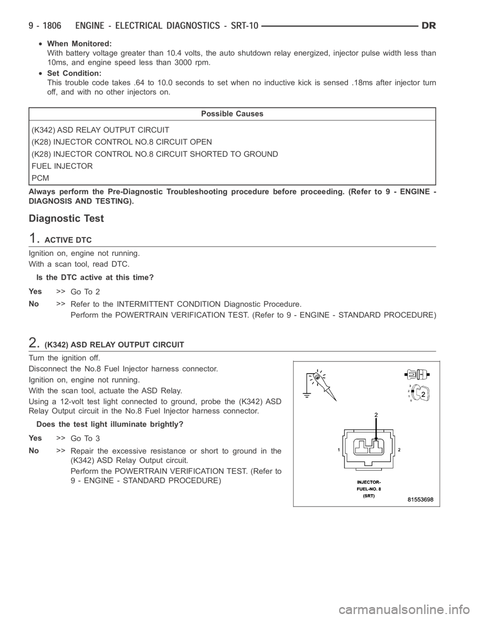
2.(K342) ASD RELAY OUTPUT CIRCUIT
Turn the ignition off.
Disconnect the No.8 Fuel Injector harness connector.
Ignition on, engine not running.
With the scan tool, actuate the ASD Relay.
Using a 12-volt test light connected to ground, probe the (K342) ASD
Relay Output circuit in the No.8 Fuel Injector harness connector.
Does the test light illuminate brightly?
Ye s>>
Go To 3
No>>
Repair the excessive resistanceorshorttogroundinthe
(K342) ASD Relay Output circuit.
Perform the POWERTRAIN VERIFICATION TEST. (Refer to
9 - ENGINE - STANDARD PROCEDURE)
Page 1119 of 5267
When Monitored:
With battery voltage greater than 10.4 volts, the auto shutdown relay energized, injector pulse width less than
10ms, and engine speed less than 3000 rpm.
Set Condition:
This trouble code takes .64 to 10.0 seconds to set when no inductive kick is sensed .18ms after injector turn
off, and with no other injectors on.
Possible Causes
(K342) ASD RELAY OUTPUT CIRCUIT
(K115) INJECTOR CONTROL NO.9 CIRCUIT OPEN
(K115) INJECTOR CONTROL NO.9 CIRCUIT SHORTED TO GROUND
FUEL INJECTOR
PCM
Always perform the Pre-Diagnostic Troubleshooting procedure before proceeding. (Refer to 9 - ENGINE -
DIAGNOSIS AND TESTING).
Diagnostic Test
1.ACTIVE DTC
Ignition on, engine not running.
With a scan tool, read DTC.
Is the DTC active at this time?
Ye s>>
Go To 2
No>>
Refer to the INTERMITTENT CONDITION Diagnostic Procedure.
Perform the POWERTRAIN VERIFICATION TEST. (Refer to 9 - ENGINE - STANDARD PROCEDURE)
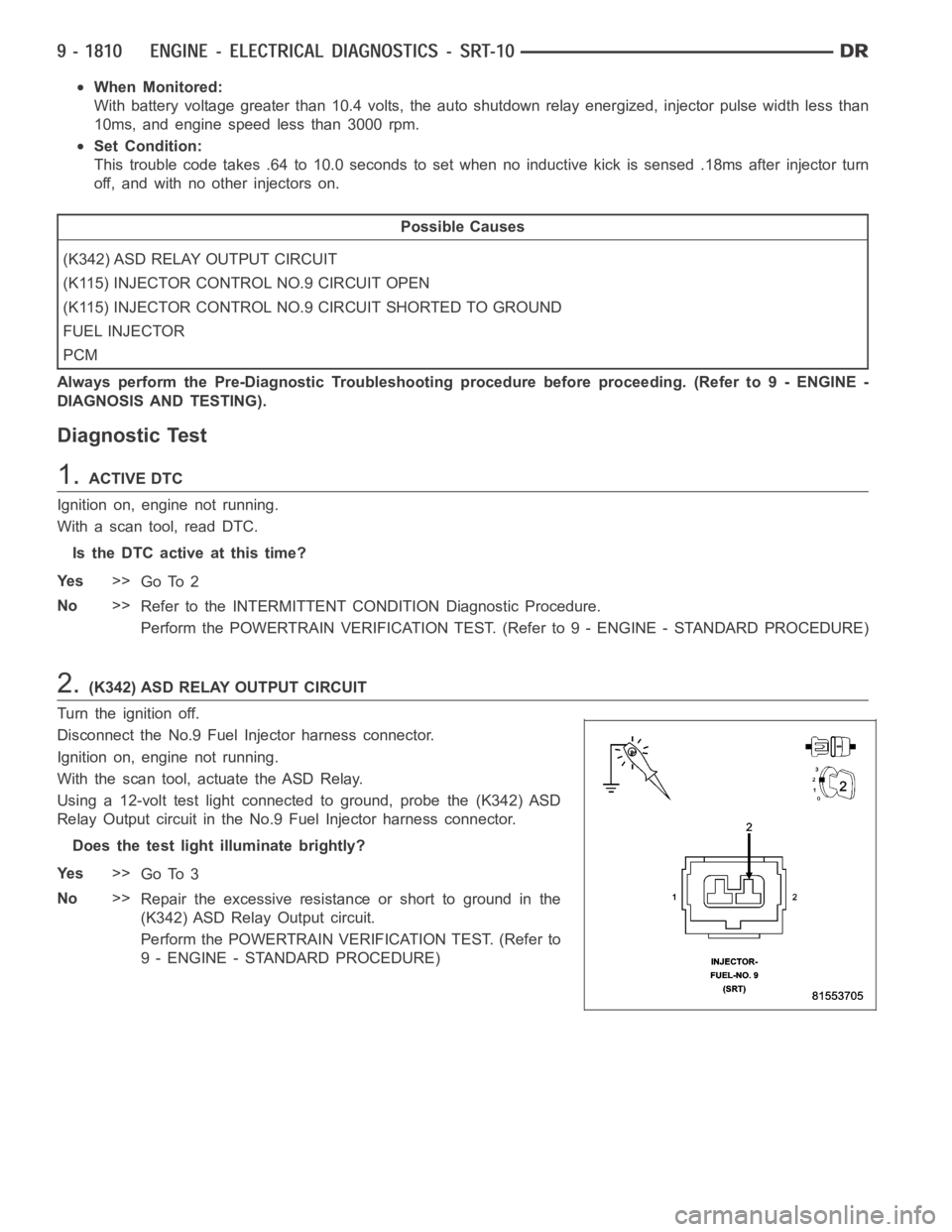
2.(K342) ASD RELAY OUTPUT CIRCUIT
Turn the ignition off.
Disconnect the No.9 Fuel Injector harness connector.
Ignition on, engine not running.
With the scan tool, actuate the ASD Relay.
Using a 12-volt test light connected to ground, probe the (K342) ASD
Relay Output circuit in the No.9 Fuel Injector harness connector.
Does the test light illuminate brightly?
Ye s>>
Go To 3
No>>
Repair the excessive resistanceorshorttogroundinthe
(K342) ASD Relay Output circuit.
Perform the POWERTRAIN VERIFICATION TEST. (Refer to
9 - ENGINE - STANDARD PROCEDURE)
Page 1123 of 5267
When Monitored:
With battery voltage greater than 10.4 volts, the auto shutdown relay energized, injector pulse width less than
10ms, and engine speed less than 3000 rpm.
Set Condition:
This trouble code takes .64 to 10.0 seconds to set when no inductive kick is sensed .18ms after injector turn
off, and with no other injectors on.
Possible Causes
(K342) ASD RELAY OUTPUT CIRCUIT
(K116) INJECTOR CONTROL NO.10 CIRCUIT OPEN
(K116) INJECTOR CONTROL NO.10 CIRCUIT SHORTED TO GROUND
FUEL INJECTOR
PCM
Always perform the Pre-Diagnostic Troubleshooting procedure before proceeding. (Refer to 9 - ENGINE -
DIAGNOSIS AND TESTING).
Diagnostic Test
1.ACTIVE DTC
Ignition on, engine not running.
With a scan tool, read DTC.
Is the DTC active at this time?
Ye s>>
Go To 2
No>>
Refer to the INTERMITTENT CONDITION Diagnostic Procedure.
Perform the POWERTRAIN VERIFICATION TEST. (Refer to 9 - ENGINE - STANDARD PROCEDURE)
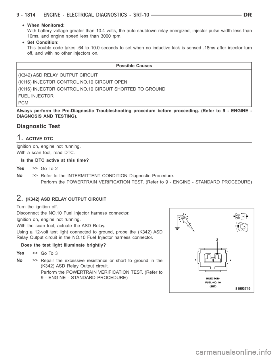
2.(K342) ASD RELAY OUTPUT CIRCUIT
Turn the ignition off.
Disconnect the NO.10 Fuel Injector harness connector.
Ignition on, engine not running.
With the scan tool, actuate the ASD Relay.
Using a 12-volt test light connected to ground, probe the (K342) ASD
Relay Output circuit in the NO.10 Fuel Injector harness connector.
Does the test light illuminate brightly?
Ye s>>
Go To 3
No>>
Repair the excessive resistanceorshorttogroundinthe
(K342) ASD Relay Output circuit.
Perform the POWERTRAIN VERIFICATION TEST. (Refer to
9 - ENGINE - STANDARD PROCEDURE)
Page 1223 of 5267
When Monitored:
Engine cranking.
Set Condition:
No CKP signal is present during engine cranking, and at least 8 camshaft position sensor signals have
occurred. One Trip Fault. Three good trips to turn off the MIL.
Possible Causes
(F855) 5-VOLT SUPPLY CIRCUIT SHORTED TO BATTERY VOLTAGE
(F855) 5-VOLT SUPPLY CIRCUIT OPEN
(F855) 5-VOLT SUPPLY CIRCUIT SHORTED TO GROUND
(K24) CKP SIGNAL CIRCUIT OPEN
(K24) CKP SIGNAL CIRCUIT SHORTED TO BATTERY VOLTAGE
(K24) CKP SIGNAL CIRCUIT SHORTED GROUND
(K24) CKP SIGNAL CIRCUIT SHORTED TO THE (F855) 5-VOLT SUPPLY CIRCUIT
(K900) SENSOR GROUND CIRCUIT OPEN
CRANKSHAFT POSITION SENSOR
CAMSHAFT POSITION SENSOR
PCM
Always perform the Pre-Diagnostic Troubleshooting procedure before proceeding. (Refer to 9 - ENGINE -
DIAGNOSIS AND TESTING).
Diagnostic Test
1.ACTIVE DTC
Crank the engine.
Ignition on, engine not running.
With a scan tool, read DTCs.
Is the DTC active at this time?
Ye s>>
Go To 2
No>>
Go To 14
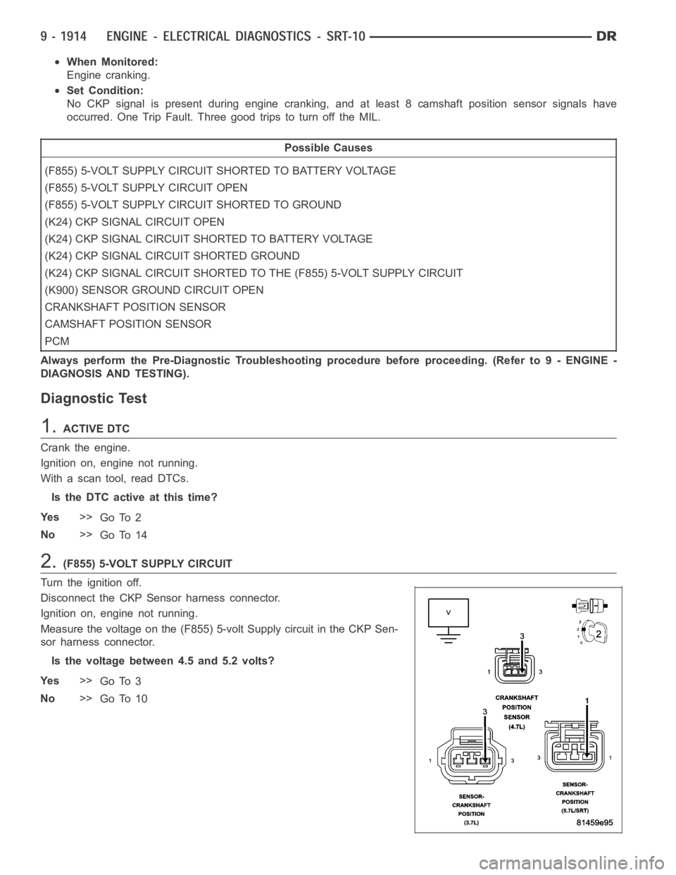
2.(F855) 5-VOLT SUPPLY CIRCUIT
Turn the ignition off.
Disconnect the CKP Sensor harness connector.
Ignition on, engine not running.
Measure the voltage on the (F855) 5-volt Supply circuit in the CKP Sen-
sor harness connector.
Is the voltage between 4.5 and 5.2 volts?
Ye s>>
Go To 3
No>>
Go To 10
Page 1225 of 5267
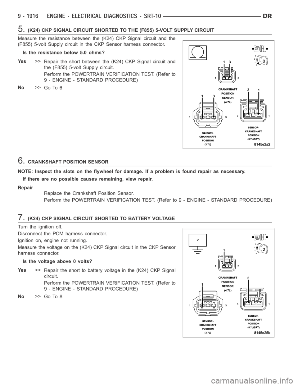
5.(K24) CKP SIGNAL CIRCUIT SHORTED TO THE (F855) 5-VOLT SUPPLY CIRCUIT
Measure the resistance between the (K24) CKP Signal circuit and the
(F855) 5-volt Supply circuit in the CKP Sensor harness connector.
Is the resistance below 5.0 ohms?
Ye s>>
Repair the short between the (K24) CKP Signal circuit and
the (F855) 5-volt Supply circuit.
Perform the POWERTRAIN VERIFICATION TEST. (Refer to
9 - ENGINE - STANDARD PROCEDURE)
No>>
Go To 6
6.CRANKSHAFT POSITION SENSOR
NOTE: Inspect the slots on the flywheel for damage. If a problem is found repair as necessary.
If there are no possible causes remaining, view repair.
Repair
Replace the Crankshaft Position Sensor.
Perform the POWERTRAIN VERIFICATION TEST. (Refer to 9 - ENGINE - STANDARD PROCEDURE)
7.(K24) CKP SIGNAL CIRCUIT SHORTED TO BATTERY VOLTAGE
Turn the ignition off.
Disconnect the PCM harness connector.
Ignition on, engine not running.
Measure the voltage on the (K24) CKP Signal circuit in the CKP Sensor
harness connector.
Is the voltage above 0 volts?
Ye s>>
Repair the short to battery voltage in the (K24) CKP Signal
circuit.
Perform the POWERTRAIN VERIFICATION TEST. (Refer to
9 - ENGINE - STANDARD PROCEDURE)
No>>
Go To 8
Page 1227 of 5267
10.(F855) 5-VOLT SUPPLY CIRCUIT SHORTED TO BATTERY VOLTAGE
Turn the ignition off.
Disconnect the PCM harness connector.
Ignition on, engine not running.
Measure the voltage on the (F855) 5-volt Supply circuit in the CKP Sen-
sor harness connector.
Is the voltage above 0 volts?
Ye s>>
Repair the short to battery voltage in the (F855) 5-volt Sup-
ply circuit.
Perform the POWERTRAIN VERIFICATION TEST. (Refer to
9 - ENGINE - STANDARD PROCEDURE)
No>>
Go To 11
11 .(F855) 5-VOLT SUPPLY CIRCUIT OPEN
Turn the ignition off.
Measure the resistance of the (F855) 5-volt Supply circuit from the CKP
Sensor harness connector to the PCM harness connector.
Is the resistance below 5.0 ohms?
Ye s>>
Go To 12
No>>
Repair the open in the (F855) 5-volt Supply circuit.
Perform the POWERTRAIN VERIFICATION TEST. (Refer to
9 - ENGINE - STANDARD PROCEDURE)
Page 1231 of 5267
When Monitored:
Engine running.
Set Condition:
The Knock Sensor circuit voltage falls below a minimum value at idle or deceleration. The minimum value is
from a look-up table internal to the PCM and is based on engine RPM. DTC will also set if the sensor voltage
goes above 5.0 volts. One Trip Fault. Three good trips to turn off the MIL.
Possible Causes
(K42) KNOCK SENSOR NO.1 SIGNAL CIRCUIT SHORTED TO BATTERY VOLTAGE
(K42) KNOCK SENSOR NO.1 SIGNAL CIRCUIT OPEN
(K900) SENSOR GROUND CIRCUIT OPEN
(K42) KNOCK SENSOR NO.1 SIGNAL CIRCUIT SHORTED TO THE (K900) SENSOR GROUNDCIRCUIT
(K42) KNOCK SENSOR NO.1 SIGNAL CIRCUIT SHORTED TO GROUND
KNOCK SENSOR
PCM
Always perform the Pre-Diagnostic Troubleshooting procedure before proceeding. (Refer to 9 - ENGINE -
DIAGNOSIS AND TESTING).
Diagnostic Test
1.ACTIVE DTC
Ignition on, engine not running.
With a scan tool, read DTCs.
Is the DTC active at this time?
Ye s>>
Go To 2
No>>
Refer to the INTERMITTENT CONDITION Diagnostic Procedure.
Perform the POWERTRAIN VERIFICATION TEST. (Refer to 9 - ENGINE - STANDARD PROCEDURE)
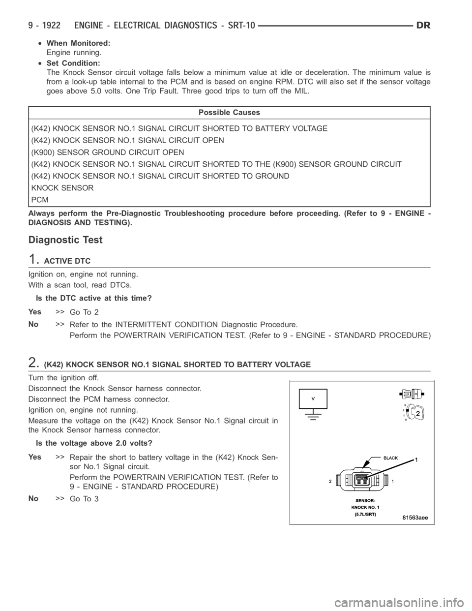
2.(K42) KNOCK SENSOR NO.1 SIGNAL SHORTED TO BATTERY VOLTAGE
Turn the ignition off.
Disconnect the Knock Sensor harness connector.
Disconnect the PCM harness connector.
Ignition on, engine not running.
Measure the voltage on the (K42) Knock Sensor No.1 Signal circuit in
the Knock Sensor harness connector.
Is the voltage above 2.0 volts?
Ye s>>
Repair the short to battery voltage in the (K42) Knock Sen-
sor No.1 Signal circuit.
Perform the POWERTRAIN VERIFICATION TEST. (Refer to
9 - ENGINE - STANDARD PROCEDURE)
No>>
Go To 3
Page 1235 of 5267
When Monitored:
Engine running
Set Condition:
The Knock Sensor circuit voltage falls below a minimum value at idle or deceleration. The minimum value is
from a look-up table internal to the PCM and is based on engine RPM. DTC well also set if the sensor voltage
goes above 5.0 volts. One Trip Fault. Three good trips to turn off the MIL. One Trip Fault. Three good trips to
turn off the MIL.
Possible Causes
(K242) KNOCK SENSOR NO.2 SIGNAL CIRCUIT SHORTED TO BATTERY VOLTAGE
(K242) KNOCK SENSOR NO.2 SIGNAL CIRCUIT OPEN
(K900) SENSOR GROUND CIRCUIT OPEN
(K242) KNOCK SENSOR NO.2 SIGNAL CIRCUIT SHORTED TO THE (K900) SENSOR GROUND CIRCUIT
(K242) KNOCK SENSOR NO.2 SIGNAL CIRCUIT SHORTED TO GROUND
KNOCK SENSOR
PCM
Always perform the Pre-Diagnostic Troubleshooting procedure before proceeding. (Refer to 9 - ENGINE -
DIAGNOSIS AND TESTING).
Diagnostic Test
1.ACTIVE DTC
Ignition on, engine not running.
With a scan tool, read DTCs.
Is the DTC active at this time?
Ye s>>
Go To 2
No>>
Refer to the INTERMITTENT CONDITION Diagnostic Procedure.
Perform the POWERTRAIN VERIFICATION TEST. (Refer to 9 - ENGINE - STANDARD PROCEDURE)
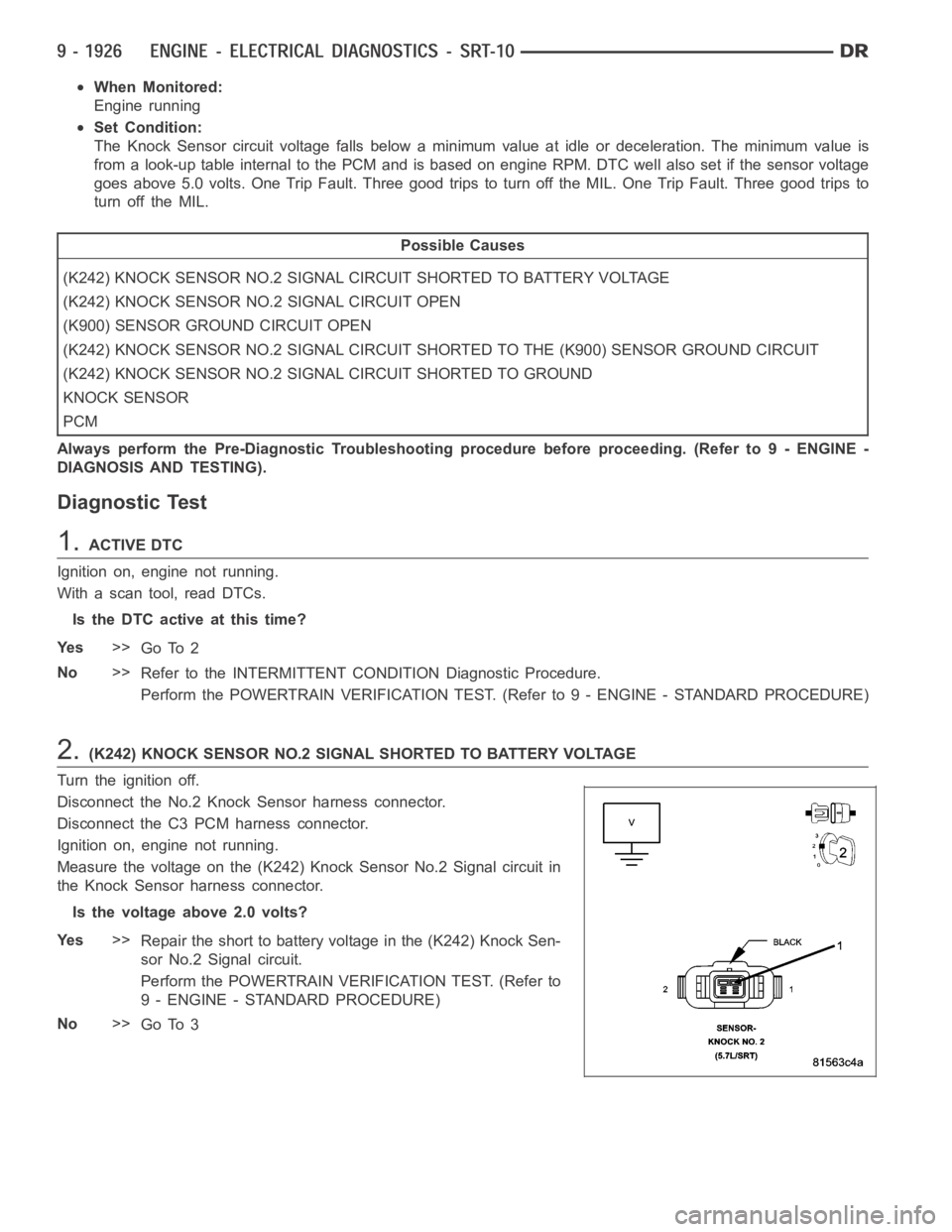
2.(K242) KNOCK SENSOR NO.2 SIGNAL SHORTED TO BATTERY VOLTAGE
Turn the ignition off.
Disconnect the No.2 Knock Sensor harness connector.
Disconnect the C3 PCM harness connector.
Ignition on, engine not running.
Measure the voltage on the (K242) Knock Sensor No.2 Signal circuit in
the Knock Sensor harness connector.
Is the voltage above 2.0 volts?
Ye s>>
Repair the short to battery voltage in the (K242) Knock Sen-
sor No.2 Signal circuit.
Perform the POWERTRAIN VERIFICATION TEST. (Refer to
9 - ENGINE - STANDARD PROCEDURE)
No>>
Go To 3