2006 DODGE RAM SRT-10 battery
[x] Cancel search: batteryPage 1001 of 5267
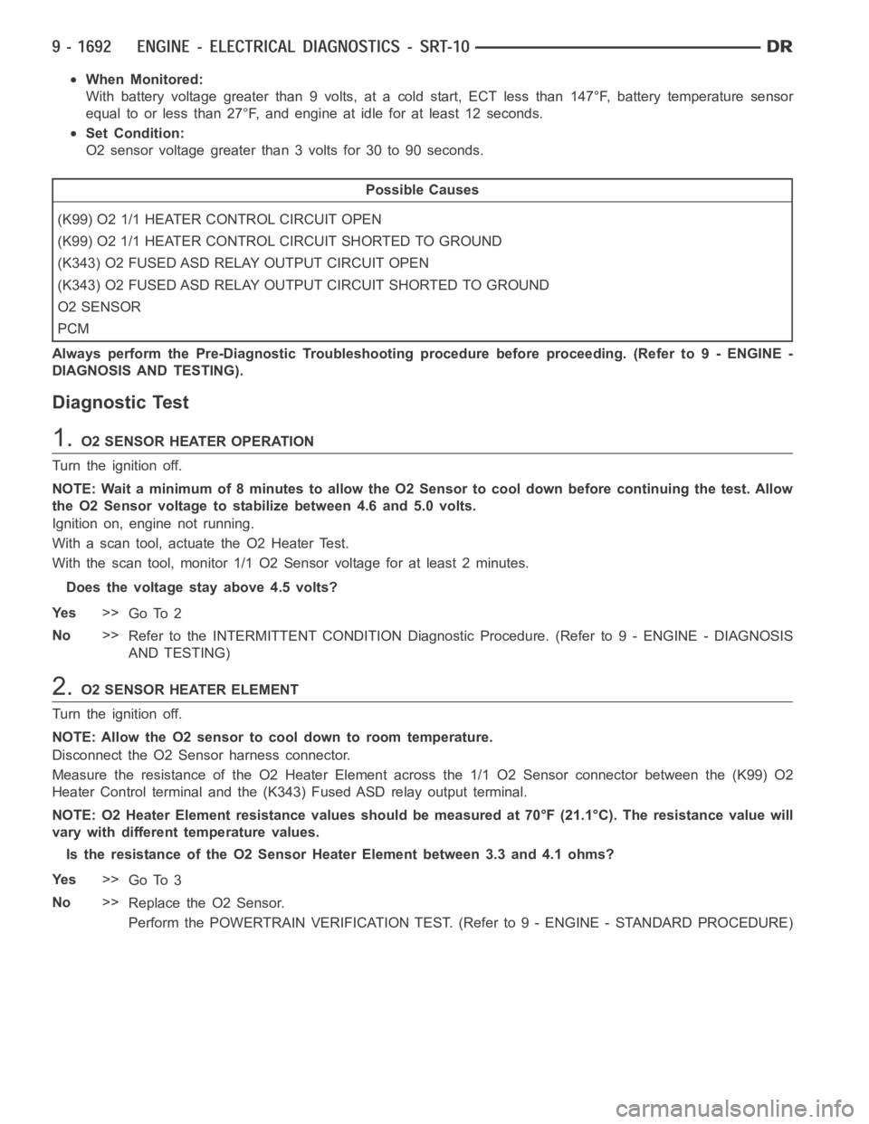
When Monitored:
With battery voltage greater than 9 volts, at a cold start, ECT less than 147°F, battery temperature sensor
equal to or less than 27°F, and engine at idle for at least 12 seconds.
Set Condition:
O2 sensor voltage greater than 3 volts for 30 to 90 seconds.
Possible Causes
(K99) O2 1/1 HEATER CONTROL CIRCUIT OPEN
(K99) O2 1/1 HEATER CONTROL CIRCUIT SHORTED TO GROUND
(K343) O2 FUSED ASD RELAY OUTPUT CIRCUIT OPEN
(K343) O2 FUSED ASD RELAY OUTPUT CIRCUIT SHORTED TO GROUND
O2 SENSOR
PCM
Always perform the Pre-Diagnostic Troubleshooting procedure before proceeding. (Refer to 9 - ENGINE -
DIAGNOSIS AND TESTING).
Diagnostic Test
1.O2 SENSOR HEATER OPERATION
Turn the ignition off.
NOTE: Wait a minimum of 8 minutes to allow the O2 Sensor to cool down before continuing the test. Allow
the O2 Sensor voltage to stabilize between 4.6 and 5.0 volts.
Ignition on, engine not running.
With a scan tool, actuate the O2 Heater Test.
With the scan tool, monitor 1/1 O2 Sensor voltage for at least 2 minutes.
Does the voltage stay above 4.5 volts?
Ye s>>
Go To 2
No>>
Refer to the INTERMITTENT CONDITION Diagnostic Procedure. (Refer to 9 - ENGINE - DIAGNOSIS
AND TESTING)
2.O2 SENSOR HEATER ELEMENT
Turn the ignition off.
NOTE: Allow the O2 sensor to cool down to room temperature.
Disconnect the O2 Sensor harness connector.
Measure the resistance of the O2 Heater Element across the 1/1 O2 Sensor connector between the (K99) O2
Heater Control terminal and the (K343) Fused ASD relay output terminal.
NOTE: O2 Heater Element resistance values should be measured at 70°F (21.1°C). The resistance value will
vary with different temperature values.
Is the resistance of the O2 Sensor Heater Element between 3.3 and 4.1 ohms?
Ye s>>
Go To 3
No>>
Replace the O2 Sensor.
Perform the POWERTRAIN VERIFICATION TEST. (Refer to 9 - ENGINE - STANDARD PROCEDURE)
Page 1004 of 5267
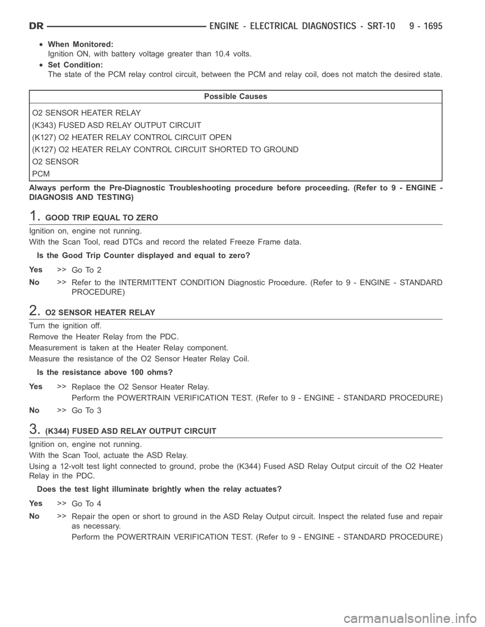
When Monitored:
Ignition ON, with battery voltage greater than 10.4 volts.
Set Condition:
The state of the PCM relay control circuit, between the PCM and relay coil, does not match the desired state.
Possible Causes
O2 SENSOR HEATER RELAY
(K343) FUSED ASD RELAY OUTPUT CIRCUIT
(K127) O2 HEATER RELAY CONTROL CIRCUIT OPEN
(K127) O2 HEATER RELAY CONTROL CIRCUIT SHORTED TO GROUND
O2 SENSOR
PCM
Always perform the Pre-Diagnostic Troubleshooting procedure before proceeding. (Refer to 9 - ENGINE -
DIAGNOSIS AND TESTING)
1.GOOD TRIP EQUAL TO ZERO
Ignition on, engine not running.
With the Scan Tool, read DTCs and record the related Freeze Frame data.
Is the Good Trip Counter displayed and equal to zero?
Ye s>>
Go To 2
No>>
Refer to the INTERMITTENT CONDITION Diagnostic Procedure. (Refer to 9 - ENGINE - STANDARD
PROCEDURE)
2.O2 SENSOR HEATER RELAY
Turn the ignition off.
Remove the Heater Relay from the PDC.
Measurement is taken at the Heater Relay component.
Measure the resistance of the O2 Sensor Heater Relay Coil.
Is the resistance above 100 ohms?
Ye s>>
Replace the O2 Sensor Heater Relay.
Perform the POWERTRAIN VERIFICATION TEST. (Refer to 9 - ENGINE - STANDARD PROCEDURE)
No>>
Go To 3
3.(K344) FUSED ASD RELAY OUTPUT CIRCUIT
Ignition on, engine not running.
With the Scan Tool, actuate the ASD Relay.
Using a 12-volt test light connected to ground, probe the (K344) Fused ASD Relay Output circuit of the O2 Heater
Relay in the PDC.
Does the test light illuminate brightly when the relay actuates?
Ye s>>
Go To 4
No>>
Repair the open or short to ground in the ASD Relay Output circuit. Inspect the related fuse and repair
as necessary.
Perform the POWERTRAIN VERIFICATION TEST. (Refer to 9 - ENGINE - STANDARD PROCEDURE)
Page 1007 of 5267
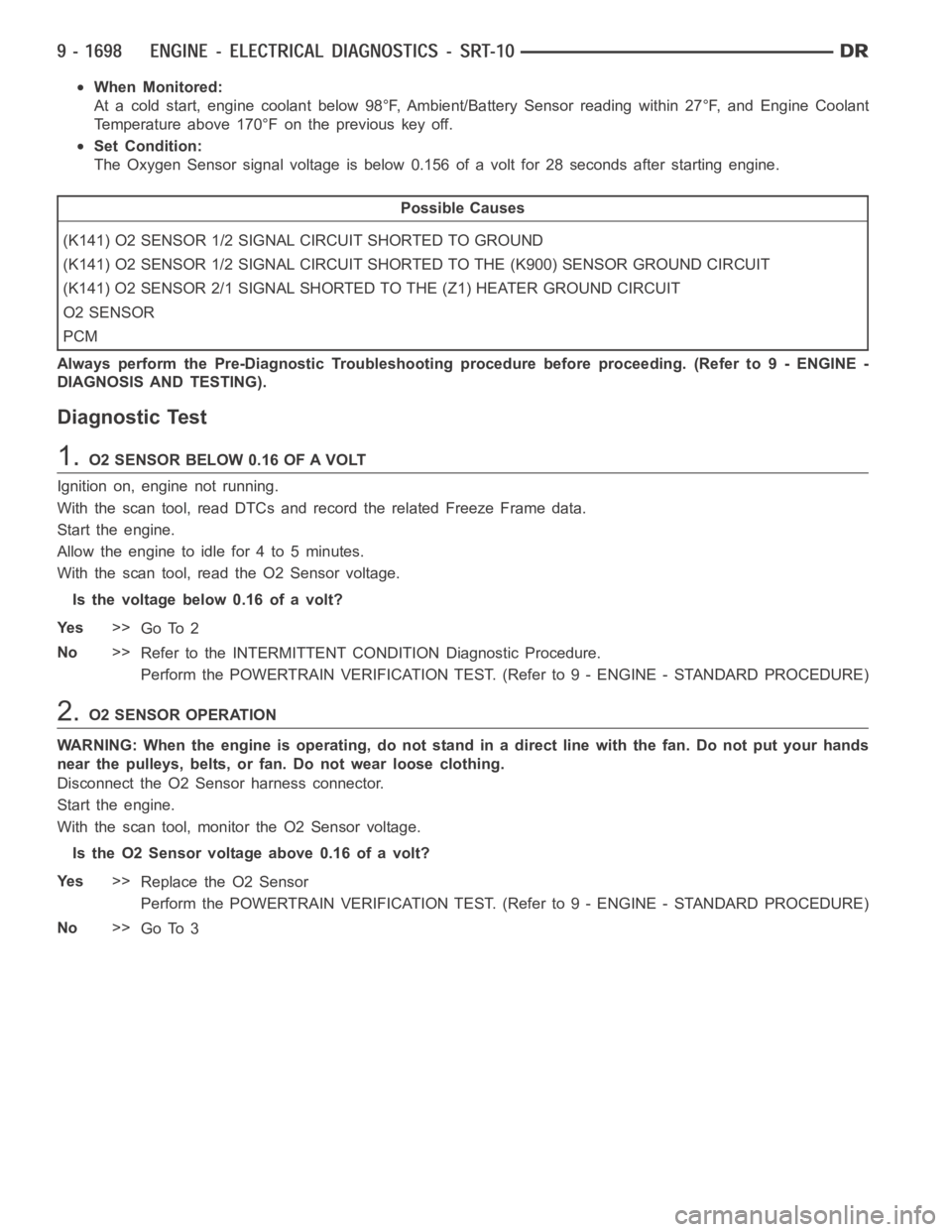
When Monitored:
At a cold start, engine coolant below 98°F, Ambient/Battery Sensor readingwithin27°F,andEngineCoolant
Temperature above 170°F on the previous key off.
Set Condition:
The Oxygen Sensor signal voltage is below 0.156 of a volt for 28 seconds after starting engine.
Possible Causes
(K141) O2 SENSOR 1/2 SIGNAL CIRCUIT SHORTED TO GROUND
(K141) O2 SENSOR 1/2 SIGNAL CIRCUIT SHORTED TO THE (K900) SENSOR GROUND CIRCUIT
(K141) O2 SENSOR 2/1 SIGNAL SHORTED TO THE (Z1) HEATER GROUND CIRCUIT
O2 SENSOR
PCM
Always perform the Pre-Diagnostic Troubleshooting procedure before proceeding. (Refer to 9 - ENGINE -
DIAGNOSIS AND TESTING).
Diagnostic Test
1.O2 SENSOR BELOW 0.16 OF A VOLT
Ignition on, engine not running.
With the scan tool, read DTCs and record the related Freeze Frame data.
Start the engine.
Allow the engine to idle for 4 to 5 minutes.
With the scan tool, read the O2 Sensor voltage.
Is the voltage below 0.16 of a volt?
Ye s>>
Go To 2
No>>
Refer to the INTERMITTENT CONDITION Diagnostic Procedure.
Perform the POWERTRAIN VERIFICATION TEST. (Refer to 9 - ENGINE - STANDARD PROCEDURE)
2.O2 SENSOR OPERATION
WARNING: When the engine is operating, do not stand in a direct line with thefan. Do not put your hands
near the pulleys, belts, or fan. Do not wear loose clothing.
Disconnect the O2 Sensor harness connector.
Start the engine.
With the scan tool, monitor the O2 Sensor voltage.
IstheO2Sensorvoltageabove0.16ofavolt?
Ye s>>
Replace the O2 Sensor
Perform the POWERTRAIN VERIFICATION TEST. (Refer to 9 - ENGINE - STANDARD PROCEDURE)
No>>
Go To 3
Page 1011 of 5267
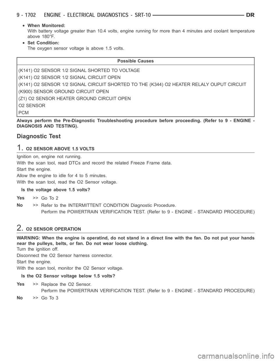
When Monitored:
With battery voltage greater than 10.4 volts, engine running for more than4 minutes and coolant temperature
above 180°F.
Set Condition:
The oxygen sensor voltage is above 1.5 volts.
Possible Causes
(K141) O2 SENSOR 1/2 SIGNAL SHORTED TO VOLTAGE
(K141) O2 SENSOR 1/2 SIGNAL CIRCUIT OPEN
(K141) O2 SENSOR 1/2 SIGNAL CIRCUIT SHORTED TO THE (K344) O2 HEATER RELALY OUPUT CIRCUIT
(K900) SENSOR GROUND CIRCUIT OPEN
(Z1) O2 SENSOR HEATER GROUND CIRCUIT OPEN
O2 SENSOR
PCM
Always perform the Pre-Diagnostic Troubleshooting procedure before proceeding. (Refer to 9 - ENGINE -
DIAGNOSIS AND TESTING).
Diagnostic Test
1.O2 SENSOR ABOVE 1.5 VOLTS
Ignition on, engine not running.
With the scan tool, read DTCs and record the related Freeze Frame data.
Start the engine.
Allow the engine to idle for 4 to 5 minutes.
With the scan tool, read the O2 Sensor voltage.
Is the voltage above 1.5 volts?
Ye s>>
Go To 2
No>>
Refer to the INTERMITTENT CONDITION Diagnostic Procedure.
Perform the POWERTRAIN VERIFICATION TEST. (Refer to 9 - ENGINE - STANDARD PROCEDURE)
2.O2 SENSOR OPERATION
WARNING: When the engine is operatind, do not stand in a direct line with thefan. Do not put your hands
near the pulleys, belts, or fan. Do not wear loose clothing.
Turn the ignition off.
Disconnect the O2 Sensor harness connector.
Start the engine.
With the scan tool, monitor the O2 Sensor voltage.
Is the O2 Sensor voltage below 1.5 volts?
Ye s>>
Replace the O2 Sensor.
Perform the POWERTRAIN VERIFICATION TEST. (Refer to 9 - ENGINE - STANDARD PROCEDURE)
No>>
Go To 3
Page 1016 of 5267
Theory of Operation
The downstream O2 Sensor is located in the exhaust path behind the catalytic converter, is monitored for proper
response to assure optimum catalytic converter efficiency. The downstream O2 response monitor is intended to
diagnose a downstream O2 sensor that is not moving or stuck in a voltage window and to insure accurate infor-
mation for catalyst monitor diagnosis.
When Monitored:
Start engine. Allow engine to idle. For 1st part of test, if limits are exceeded, test passes. If not, 2nd part of
test runs. amb/batt temp >44°F, Baro >22.13
H2O, battery >10.5 volts, MAP >11.79 & <18.15H2O, RPM
>1350 & <2200 and vss >50 and <65.
Set Condition:
The oxygen sensor signal voltage is switching from below 0.39 of a volt to above 0.58 of a volt and back fewer
times than required.
Possible Causes
EXHAUST LEAK
(K141) O2 1/2 SIGNAL CIRCUIT
(K900) SENSOR GROUND CIRCUIT
O2 SENSOR
Always perform the Pre-Diagnostic Troubleshooting procedure before proceeding. (Refer to 9 - ENGINE -
DIAGNOSIS AND TESTING).
Diagnostic Test
1.ACTIVE DTC
NOTE: Check for contaminants that may have damaged the O2 Sensor: contaminated fuel, unapproved sil-
icone, oil and coolant.
Ignition on, engine not running.
NOTE: After the repairs have been made, verify proper O2 Sensor operation.If all the O2 Sensor voltage
readings have not returned to normal, follow the diagnostic procedure forthe remaining O2 Sensors.
With a scan tool, read DTCs.
Is the DTC active at this time?
Ye s>>
Go To 2
No>>
Refer to the INTERMITTENT CONDITION Symptom. (Refer to 9 - ENGINE - STANDARD PROCE-
DURE)
2.EXHAUST LEAK
Start the engine.
Inspect the exhaust system for leaks between the engine and the O2 Sensors.
Are there any exhaust leaks?
Ye s>>
Repair or replace the leaking exhaust parts as necessary.
Perform the POWERTRAIN VERIFICATION TEST. (Refer to 9 - ENGINE - STANDARD PROCEDURE)
No>>
Go To 3
Page 1019 of 5267
Theory of Operation
This diagnostic provides a continuous check of the O2 heater circuit during operation. The heater circuit is momen-
tarily disabled to allow a resistance measurement to be taken to infer heater temperature. The current delivery to
the heater is duty cycled to maintain a specific target temperature. The error from the target temperature is contin-
uously monitored to assess heater performance.
When Monitored:
With battery voltage greater than 10.5 volts, at a cold start, ECT less than147°F, battery temperature sensor
equal to or less than 27°F, and engine at idle for at least 12 seconds.
Set Condition:
O2 sensor voltage greater than 3 volts for 60 to 240 seconds.
Possible Causes
(K344) O2 SENSOR HEATER RELAY OUTPUT CIRCUIT OPEN
(K344) O2 SENSOR HEATER RELAY OUTPUT CIRCUIT SHORTED TO GROUND
(K127) O2 HEATER RELAY CONTROL CIRCUIT OPEN
(K127) O2 HEATER RELAY CONTROL CIRCUIT SHORTED TO GROUND
(Z1) HEATER GROUND CIRCUIT OPEN
O2 SENSOR
PCM
Always perform the Pre-Diagnostic Troubleshooting procedure before proceeding. (Refer to 9 - ENGINE -
DIAGNOSIS AND TESTING).
Diagnostic Test
1.O2 SENSOR HEATER OPERATION
Turn the ignition off.
NOTE: Wait a minimum of 8 minutes to allow the O2 Sensor to cool down before continuing the test.
Ignition on, engine not running.
With the scan tool, actuate the O2 Heater Test.
With the scan tool, monitor O2 Sensor voltage for at least 2 minutes.
Does the voltage stabilize between 0.1 and 0.3 of a volt during the Heater test?
Ye s>>
Refer to the INTERMITTENT CONDITION Diagnostic Procedure.
Perform the POWERTRAIN VERIFICATION TEST. (Refer to 9 - ENGINE - STANDARD PROCEDURE)
No>>
Go To 2
2.O2 SENSOR HEATER ELEMENT
Turn the ignition off.
NOTE: Allow the O2 Sensor to cool to room temperature.
Disconnect the O2 Sensor harness connector.
Measure the resistance across the O2 Sensor Heater element component side.
NOTE: The resistance value will increase with warmer temperatures.
Is the resistance between 4.0 and 5.0 ohms at 70° F (21.1°C)?
Ye s>>
Go To 3
No>>
Replace the O2 Sensor.
Perform the POWERTRAIN VERIFICATION TEST. (Refer to 9 - ENGINE - STANDARD PROCEDURE)
Page 1023 of 5267
When Monitored:
At a cold start, engine coolant below 98°F, Ambient/Battery Sensor readingwithin27°F,andEngineCoolant
Temperature above 170°F on the previous key off.
Set Condition:
The Oxygen Sensor signal voltage is below 0.156 of a volt for 28 seconds after starting engine.
Possible Causes
(K43) O2 2/1 SIGNAL CIRCUIT SHORTED TO GROUND
(K43) O2 2/1 SIGNAL CIRCUIT SHORTED TO THE (K900) SENSOR GROUND CIRCUIT
O2 SENSOR
PCM
Always perform the Pre-Diagnostic Troubleshooting procedure before proceeding. (Refer to 9 - ENGINE -
DIAGNOSIS AND TESTING).
Diagnostic Test
1.O2 SENSOR BELOW 0.16 OF A VOLT
Ignition on, engine not running.
With the scan tool, read DTCs and record the related Freeze Frame data.
Start the engine.
Allow the engine to idle for 4 to 5 minutes.
With the scan tool, read the O2 Sensor voltage.
Is the voltage below 0.16 of a volt?
Ye s>>
Go To 2
No>>
Refer to the INTERMITTENT CONDITION Diagnostic Procedure.
Perform the POWERTRAIN VERIFICATION TEST. (Refer to 9 - ENGINE - STANDARD PROCEDURE)
2.O2 SENSOR OPERATION
WARNING: When the engine is operating, do not stand in a direct line with thefan. Do not put your hands
near the pulleys, belts, or fan. Do no wear loose clothing.
Disconnect the O2 Sensor harness connector.
Start the engine.
With the scan tool, monitor the O2 Sensor voltage.
IstheO2Sensorvoltageabove0.16ofavolt?
Ye s>>
Replace the O2 Sensor.
Perform the POWERTRAIN VERIFICATION TEST. (Refer to 9 - ENGINE - STANDARD PROCEDURE)
No>>
Go To 3
Page 1026 of 5267
When Monitored:
With battery voltage greater than 10.4 volts, engine running for more than4 minutes and coolant temperature
above 180°F.
Set Condition:
The oxygen sensor voltage is above 1.5 volts.
Possible Causes
(K43) O2 2/1 SIGNAL CIRCUIT SHORTED TO VOLTAGE
(K199) O2 SENSOR 2/1 HEATER CONTROL CIRCUIT OPEN
(K43) O2 2/1 SIGNAL CIRCUIT OPEN
(K900) SENSOR GROUND CIRCUIT OPEN
(K343) ASD RELAY OUTPUT CIRCUIT OPEN
(K43) O2 2/1 SIGNAL CIRCUIT SHORTED TO THE (K343) ASD RELAY OUTPUT CIRCUIT
O2 SENSOR
PCM
Always perform the Pre-Diagnostic Troubleshooting procedure before proceeding. (Refer to 9 - ENGINE -
DIAGNOSIS AND TESTING).
Diagnostic Test
1.O2 SENSOR ABOVE 1.5 VOLTS
Ignition on, engine not running.
With the scan tool, read DTCs and record the related Freeze Frame data.
Start the engine.
Allow the engine to idle for 4 to 5 minutes.
With the scan tool, read the O2 Sensor voltage.
Is the voltage above 1.5 volts?
Ye s>>
Go To 2
No>>
Refer to the INTERMITTENT CONDITION Diagnostic Procedure.
Perform the POWERTRAIN VERIFICATION TEST. (Refer to 9 - ENGINE - STANDARD PROCEDURE)
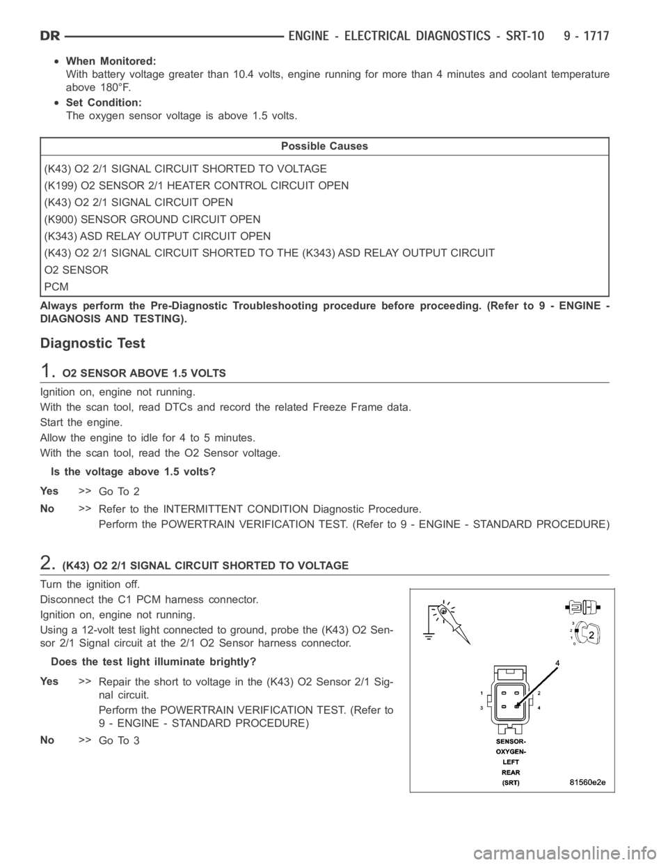
2.(K43) O2 2/1 SIGNAL CIRCUIT SHORTED TO VOLTAGE
Turn the ignition off.
Disconnect the C1 PCM harness connector.
Ignition on, engine not running.
Using a 12-volt test light connected to ground, probe the (K43) O2 Sen-
sor 2/1 Signal circuit at the 2/1 O2 Sensor harness connector.
Does the test light illuminate brightly?
Ye s>>
Repair the short to voltage in the (K43) O2 Sensor 2/1 Sig-
nal circuit.
Perform the POWERTRAIN VERIFICATION TEST. (Refer to
9 - ENGINE - STANDARD PROCEDURE)
No>>
Go To 3