Page 1537 of 3171
WHEEL HUB
FAX-5
C
E
F
G
H
I
J
K
L
MA
B
FA X
WHEEL HUBPFP:43202
On-Vehicle Inspection and ServiceEDS003I7
Make sure the mounting conditions (looseness, backlash) of each component and component status (wear,
damage) are normal.
WHEEL BEARING INSPECTION
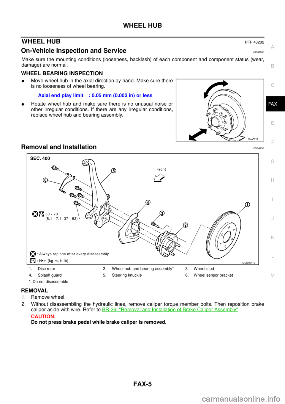
lMove wheel hub in the axial direction by hand. Make sure there
is no looseness of wheel bearing.
lRotate wheel hub and make sure there is no unusual noise or
other irregular conditions. If there are any irregular conditions,
replace wheel hub and bearing assembly.
Removal and InstallationEDS003I8
REMOVAL
1. Remove wheel.
2. Without disassembling the hydraulic lines, remove caliper torque member bolts. Then reposition brake
caliper aside with wire. Refer toBR-26, "
Removal and Installation of Brake Caliper Assembly".
CAUTION:
Do not press brake pedal while brake caliper is removed.Axial end play limit : 0.05 mm (0.002 in) or less
SMA571A
1. Disc rotor 2. Wheel hub and bearing assembly* 3. Wheel stud
4. Splash guard 5. Steering knuckle 6. Wheel sensor bracket
*: Do not disassemble
MDIB9011E
Page 1546 of 3171
FAX-14
SERVICE DATA AND SPECIFICATIONS (SDS)
SERVICE DATA AND SPECIFICATIONS (SDS)
PFP:00030
Wheel BearingEDS003IB
Drive ShaftEDS003IC
Wheel bearing axial end play 0.05 mm (0.002 in) or less
Wheel Side Final Drive Side
Applied modelEngine YD25, VQ40
Transaxle MT AT
Drive shaft joint type Final drive side AAR3300I AAR3300I
Wheel side UF3700I AC3300I
GreaseQuality Nissan genuine grease or equivalent
Capacity g (oz)Final drive side 134 - 144 (4.73 - 5.08) 134 - 144 (4.73 - 5.08)
Wheel side 226 - 246 (7.97 - 8.68) 110 - 130 (3.88 - 4.59)
Boot length “L” mm (in)Final drive side 176 - 178 (6.93 - 7.01) 176 - 178 (6.93 - 7.01)
Wheel side 154 (6.06) 150.4 (5.92)
MDIB9038EMDIB9037E
Page 1547 of 3171
FFD-1
FRONT FINAL DRIVE
D DRIVELINE/AXLE
CONTENTS
C
E
F
G
H
I
J
K
L
M
SECTIONFFD
A
B
FFD
FRONT FINAL DRIVE
PRECAUTIONS .......................................................... 2
Service Notice or Precautions .................................. 2
PREPARATION ........................................................... 3
Special Service Tools ............................................... 3
Commercial Service Tools ........................................ 5
NOISE, VIBRATION AND HARSHNESS (NVH)
TROUBLESHOOTING ................................................ 6
NVH Troubleshooting Chart ..................................... 6
DESCRIPTION ............................................................ 7
Cross-Sectional View ............................................... 7
DIFFERENTIAL GEAR OIL ........................................ 8
Changing Differential Gear Oil ................................. 8
DRAINING ............................................................. 8
FILLING ................................................................. 8
Checking Differential Gear Oil .................................. 8
OIL LEAKAGE AND OIL LEVEL ........................... 8
FRONT OIL SEAL ...................................................... 9
Removal and Installation .......................................... 9
IDENTIFICATION STAMP OF REPLACEMENT
FREQUENCY OF FRONT OIL SEAL ................... 9
REMOVAL ............................................................. 9
INSTALLATION .................................................... 11
SIDE OIL SEAL ........................................................ 13
Removal and Installation ........................................ 13
REMOVAL ........................................................... 13
INSTALLATION ................................................... 13REAR COVER GASKET ........................................... 14
Removal and Installation ........................................ 14
REMOVAL ........................................................... 14
INSTALLATION ................................................... 14
FRONT FINAL DRIVE ASSEMBLY .......................... 15
Removal and Installation ........................................ 15
REMOVAL ........................................................... 15
INSTALLATION ................................................... 16
Disassembly and Assembly .................................... 17
COMPONENTS ................................................... 17
ASSEMBLY INSPECTION AND ADJUSTMENT... 18
DISASSEMBLY ................................................... 21
INSPECTION AFTER DISASSEMBLY ................ 26
ADJUSTMENT AND SELECTION ADJUSTING
WASHERS .......................................................... 27
ASSEMBLY ......................................................... 28
SERVICE DATA AND SPECIFICATIONS (SDS) ...... 37
General Specifications ............................................ 37
Inspection and Adjustment ..................................... 37
DRIVE GEAR RUNOUT ...................................... 37
DIFFERENTIAL SIDE GEAR CLEARANCE ....... 37
PRELOAD TORQUE ........................................... 37
BACKLASH ......................................................... 37
COMPANION FLANGE RUNOUT ....................... 37
SELECTIVE PARTS ............................................ 37
Page 1548 of 3171
FFD-2
PRECAUTIONS
PRECAUTIONS
PFP:00001
ServiceNoticeorPrecautionsEDS0034W
lBefore starting diagnosis of the vehicle, understand the symptoms well. Perform correct and systematic
operations.
lCheck for the correct installation status prior to removal or disassembly. When matching marks are
required, be certain they do not interfere with the function of the parts they are applied to.
lOverhaul should be done in a clean work area, a dust proof area is recommended.
lBefore disassembly, completely remove sand and mud from the exterior of the unit, preventing them from
entering into the unit during disassembly or assembly.
lAlways use shop paper for cleaning the inside of components.
lAvoid using cotton gloves or a shop cloth to prevent the entering of lint.
lCheck appearance of the disassembled parts for damage, deformation, and unusual wear. Replace them
with new ones if necessary.
lGaskets, seals and O-rings should be replaced any time the unit is disassembled.
lClean and flush the parts sufficiently and blow them dry.
lBe careful not to damage sliding surfaces and mating surfaces.
lWhen applying sealant, remove the old sealant from the mating surface; then remove any moisture, oil,
and foreign materials from the application and mating surfaces.
lIn principle, tighten bolts or nuts gradually in several steps working diagonally from inside to outside. If a
tightening sequence is specified, observe it.
lDuring assembly, observe the specified tightening torque.
lAdd new differential gear oil, petroleum jelly, or multi-purpose grease, as specified.
Page 1549 of 3171
PREPARATION
FFD-3
C
E
F
G
H
I
J
K
L
MA
B
FFD
PREPARATIONPFP:00002
Special Service ToolsEDS0034X
Tool number
Tool nameDescription
KV381054S0
PullerRemoving front oil seal
ST30720000
Drift
a: 77 mm (3.03 in) dia.
b: 55.5 mm (2.185 in) dia.
lInstalling front oil seal
lInstalling side oil seal
ST27863000
Drift
a: 74.5 mm (2.933 in) dia.
b: 62.5 mm (2.461 in) dia.
lInstalling front oil seal
lInstalling side oil seal
ST29020001
PullerSeparating the upper link ball joint stud
ST3127S000
Preload gauge
1: GG91030000
Torque wrench
2: HT62940000
Socket adapter (1/2²)
3: HT62900000
Socket adapter (3/8²)Measuring pinion bearing preload and total
preload
K V 1 0 1111 0 0
Seal cutterRemoving rear cover
ST3306S001
Differential side bearing puller set
1: ST33051001
Puller
2: ST33061000
Base
a: 28.5 mm (1.122 in) dia.
b: 38 mm (1.50 in) dia.Removing and installing side bearing inner
race
ZZA0601D
ZZA0811D
ZZA1003D
NT143
NT124
S-NT046
NT072
Page 1551 of 3171
PREPARATION
FFD-5
C
E
F
G
H
I
J
K
L
MA
B
FFD
Commercial Service ToolsEDS0034Y
ST33230000
Drift
a: 51 mm (2.01 in) dia.
b: 41 mm (1.61 in) dia.
c: 28 mm (1.10 in) dia.Installing side bearing inner race
KV38100600
DriftInstalling side bearing adjusting shim Tool number
Tool nameDescription
ZZA1046D
SDIA0429J
Tool nameDescription
Power toolLoosening nuts and bolts
Flange wrenchRemoving and installing drive pinion lock nut
PBIC0190E
NT771
Page 1583 of 3171
SERVICE DATA AND SPECIFICATIONS (SDS)
FFD-37
C
E
F
G
H
I
J
K
L
MA
B
FFD
SERVICE DATA AND SPECIFICATIONS (SDS)PFP:00030
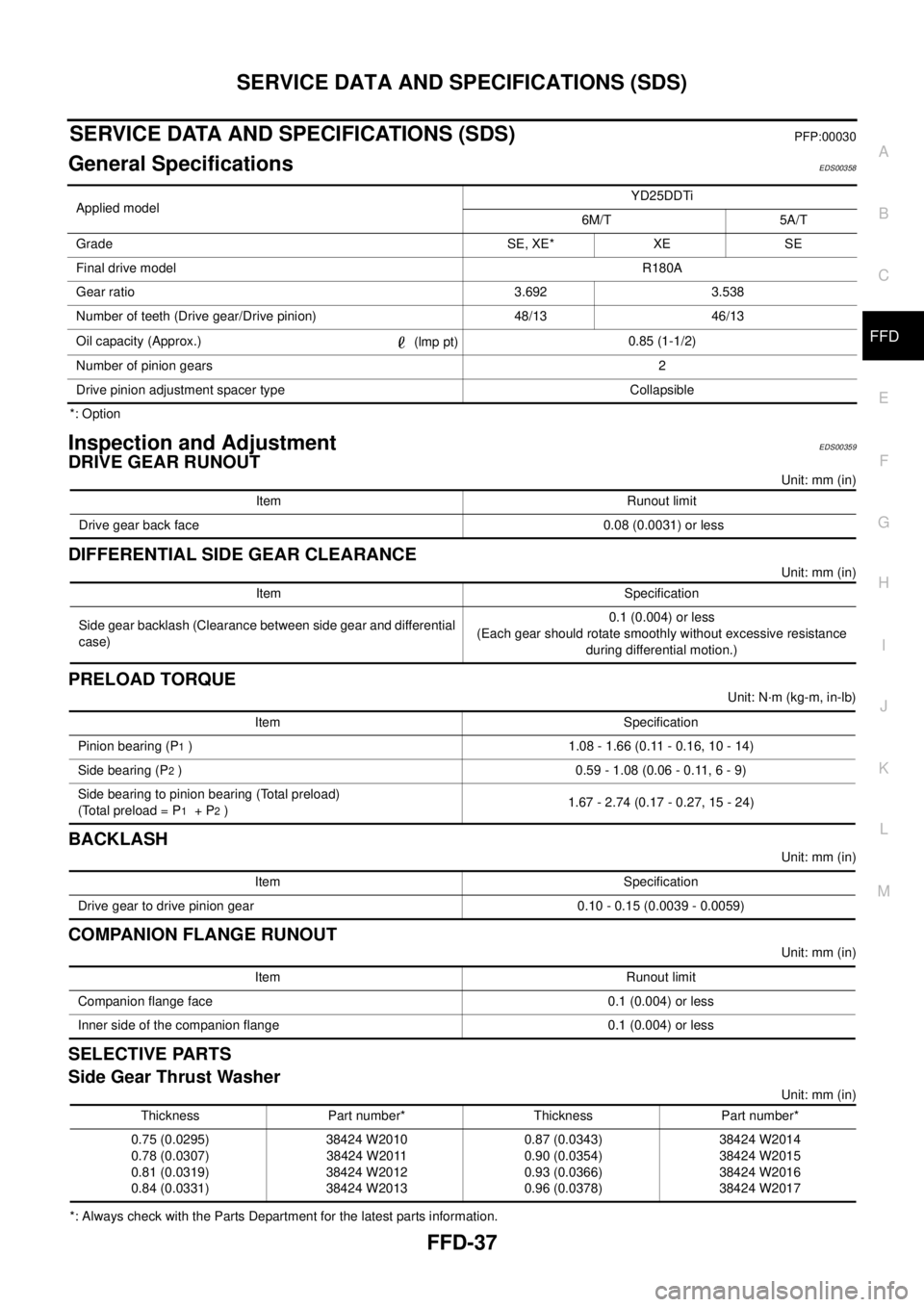
General SpecificationsEDS00358
*: Option
Inspection and AdjustmentEDS00359
DRIVE GEAR RUNOUT
Unit: mm (in)
DIFFERENTIAL SIDE GEAR CLEARANCE
Unit: mm (in)
PRELOAD TORQUE
Unit: N·m (kg-m, in-lb)
BACKLASH
Unit: mm (in)
COMPANION FLANGE RUNOUT
Unit: mm (in)
SELECTIVE PARTS
Side Gear Thrust Washer
Unit: mm (in)
*: Always check with the Parts Department for the latest parts information.Applied modelYD25DDTi
6M/T 5A/T
Grade SE, XE* XE SE
Final drive modelR180A
Gear ratio 3.692 3.538
Number of teeth (Drive gear/Drive pinion) 48/13 46/13
Oil capacity (Approx.)
(lmp pt)0.85 (1-1/2)
Number of pinion gears2
Drive pinion adjustment spacer type Collapsible
Item Runout limit
Drive gear back face 0.08 (0.0031) or less
Item Specification
Side gear backlash (Clearance between side gear and differential
case)0.1 (0.004) or less
(Each gear should rotate smoothly without excessive resistance
during differential motion.)
Item Specification
Pinion bearing (P
1) 1.08 - 1.66 (0.11 - 0.16, 10 - 14)
Side bearing (P
2) 0.59 - 1.08 (0.06 - 0.11, 6 - 9)
Side bearing to pinion bearing (Total preload)
(Total preload = P
1+P2)1.67 - 2.74 (0.17 - 0.27, 15 - 24)
Item Specification
Drive gear to drive pinion gear 0.10 - 0.15 (0.0039 - 0.0059)
Item Runout limit
Companion flange face 0.1 (0.004) or less
Inner side of the companion flange 0.1 (0.004) or less
Thickness Part number* Thickness Part number*
0.75 (0.0295)
0.78 (0.0307)
0.81 (0.0319)
0.84 (0.0331)38424 W2010
38424 W2011
38424 W2012
38424 W20130.87 (0.0343)
0.90 (0.0354)
0.93 (0.0366)
0.96 (0.0378)38424 W2014
38424 W2015
38424 W2016
38424 W2017
Page 1584 of 3171
FFD-38
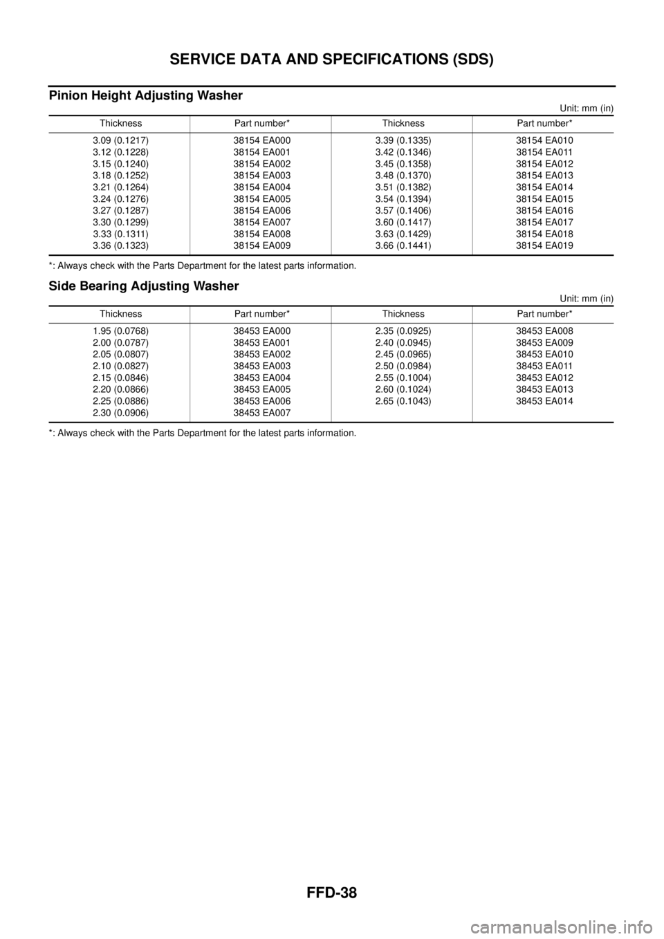
SERVICE DATA AND SPECIFICATIONS (SDS)
Pinion Height Adjusting Washer
Unit: mm (in)
*: Always check with the Parts Department for the latest parts information.
Side Bearing Adjusting Washer
Unit: mm (in)
*: Always check with the Parts Department for the latest parts information.Thickness Part number* Thickness Part number*
3.09 (0.1217)
3.12 (0.1228)
3.15 (0.1240)
3.18 (0.1252)
3.21 (0.1264)
3.24 (0.1276)
3.27 (0.1287)
3.30 (0.1299)
3.33 (0.1311)
3.36 (0.1323)38154 EA000
38154 EA001
38154 EA002
38154 EA003
38154 EA004
38154 EA005
38154 EA006
38154 EA007
38154 EA008
38154 EA0093.39 (0.1335)
3.42 (0.1346)
3.45 (0.1358)
3.48 (0.1370)
3.51 (0.1382)
3.54 (0.1394)
3.57 (0.1406)
3.60 (0.1417)
3.63 (0.1429)
3.66 (0.1441)38154 EA010
38154 EA011
38154 EA012
38154 EA013
38154 EA014
38154 EA015
38154 EA016
38154 EA017
38154 EA018
38154 EA019
Thickness Part number* Thickness Part number*
1.95 (0.0768)
2.00 (0.0787)
2.05 (0.0807)
2.10 (0.0827)
2.15 (0.0846)
2.20 (0.0866)
2.25 (0.0886)
2.30 (0.0906)38453 EA000
38453 EA001
38453 EA002
38453 EA003
38453 EA004
38453 EA005
38453 EA006
38453 EA0072.35 (0.0925)
2.40 (0.0945)
2.45 (0.0965)
2.50 (0.0984)
2.55 (0.1004)
2.60 (0.1024)
2.65 (0.1043)38453 EA008
38453 EA009
38453 EA010
38453 EA011
38453 EA012
38453 EA013
38453 EA014