Page 1523 of 3171

SERVICE DATA AND SPECIFICATIONS (SDS)
EM-141
C
D
E
F
G
H
I
J
K
L
MA
EM
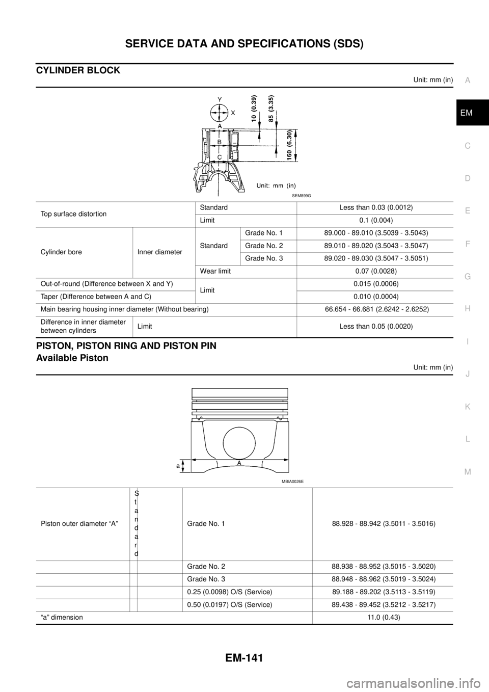
CYLINDER BLOCK
Unit: mm (in)
PISTON, PISTON RING AND PISTON PIN
Available Piston
Unit: mm (in) Top surface distortionStandard Less than 0.03 (0.0012)
Limit 0.1 (0.004)
Cylinder bore Inner diameterStandardGrade No. 1 89.000 - 89.010 (3.5039 - 3.5043)
Grade No. 2 89.010 - 89.020 (3.5043 - 3.5047)
Grade No. 3 89.020 - 89.030 (3.5047 - 3.5051)
Wear limit 0.07 (0.0028)
Out-of-round (Difference between X and Y)
Limit0.015 (0.0006)
Taper (Difference between A and C) 0.010 (0.0004)
Main bearing housing inner diameter (Without bearing) 66.654 - 66.681 (2.6242 - 2.6252)
Difference in inner diameter
between cylindersLimit Less than 0.05 (0.0020)
SEM899G
Piston outer diameter “A”S
t
a
n
d
a
r
dGrade No. 1 88.928 - 88.942 (3.5011 - 3.5016)
Grade No. 2 88.938 - 88.952 (3.5015 - 3.5020)
Grade No. 3 88.948 - 88.962 (3.5019 - 3.5024)
0.25 (0.0098) O/S (Service) 89.188 - 89.202 (3.5113 - 3.5119)
0.50 (0.0197) O/S (Service) 89.438 - 89.452 (3.5212 - 3.5217)
“a” dimension11.0 (0.43)
MBIA0026E
Page 1524 of 3171
EM-142
SERVICE DATA AND SPECIFICATIONS (SDS)
Piston pin bore diameter 28.003 - 28.009 (1.1025 - 1.1027)
Piston to cylinder bore clearance 0.058 - 0.082 (0.0023 - 0.0032)
Page 1525 of 3171
SERVICE DATA AND SPECIFICATIONS (SDS)
EM-143
C
D
E
F
G
H
I
J
K
L
MA
EM
Piston Ring
Unit: mm (in)
Piston Pin
Unit: mm (in) Item Standard Limit
Side clearanceTop 0.050 - 0.090 (0.0020 - 0.0035) 0.2 (0.008)
2nd 0.050 - 0.090 (0.0020 - 0.0035) 0.1 (0.004)
Oil ring 0.030 - 0.070 (0.0012 - 0.0028) —
End gapTop 0.21 - 0.28 (0.0083 - 0.0110)
1.0 (0.039) 2nd 0.32 - 0.47 (0.0126 - 0.0185)
Oil ring 0.30 - 0.55 (0.0118 - 0.0217)
Piston pin outer diameter 27.995 - 28.000 (1.1022 - 1.1024)
Piston to piston pin clearance 0.003 - 0.014 (0.0001 - 0.0006)
Connecting rod bushing clearanceStandard 0.026 - 0.043 (0.0010 - 0.0017)
Limit 0.057 (0.0022)
Page 1526 of 3171
EM-144
SERVICE DATA AND SPECIFICATIONS (SDS)
CONNECTING ROD
Unit: mm (in)
*: After installing in connecting rod
CRANKSHAFT
Unit: mm (in)
*: Total indicator readingCenter distance154.5 (6.083)
Bend [per 100 (3.94)] Limit 0.12 (0.0047)
Torsion [per 100 (3.94)] Limit 0.12 (0.0047)
Connecting rod bushing inner diameter* 28.026 - 28.038 (1.1034 - 1.1039)
Connecting rod big end inner diameter* 55.000 - 55.013 (2.1654 - 2.1659)
Side clearanceStandard 0.20 - 0.35 (0.0079 - 0.0138)
Limit 0.40 (0.0157)
Main journal dia. “Dm” 62.951 - 62.975 (2.4784 - 2.4793)
Pin journal dia. “Dp” 51.954 - 51.974 (2.0454 - 2.0462)
Center distance “r” 49.97 - 50.03 (1.9673 - 1.9697)
Out-of-round (Difference between X
and Y)Standard 0.003 (0.0001)
Limit 0.005 (0.0002)
Taper (Difference between A and B)Standard 0.003 (0.0001)
Limit 0.005 (0.0002)
Runout [TIR*]Standard 0.05 (0.0020)
Limit 0.10 (0.0039)
End playStandard 0.10 - 0.25 (0.0039 - 0.0098)
Limit 0.30 (0.0118)
SEM645SBIA0535E
Page 1527 of 3171

SERVICE DATA AND SPECIFICATIONS (SDS)
EM-145
C
D
E
F
G
H
I
J
K
L
MA
EM
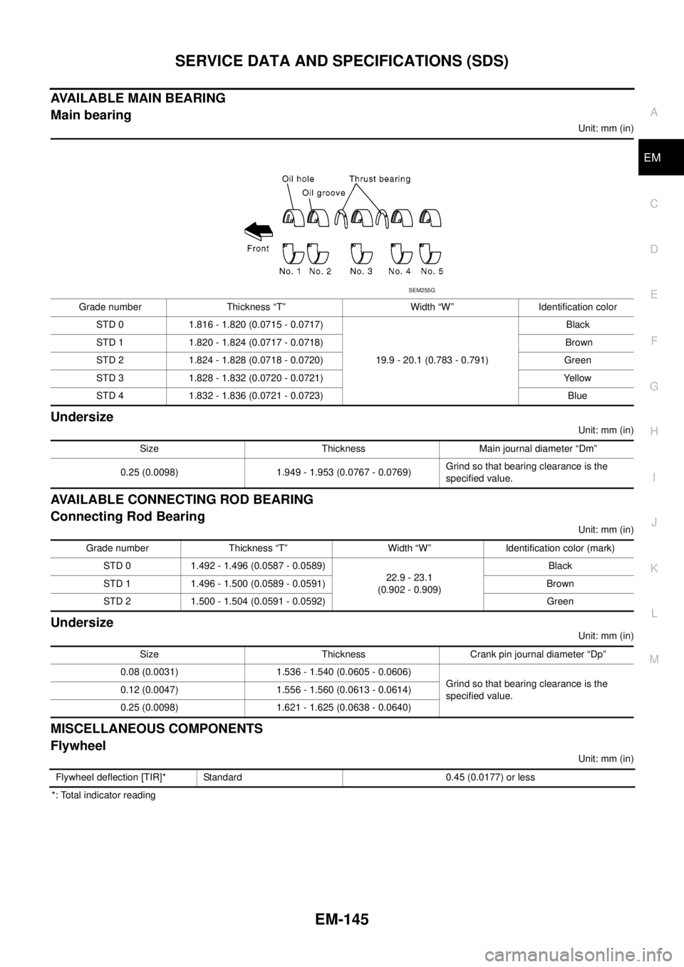
AVAILABLE MAIN BEARING
Main bearing
Unit: mm (in)
Undersize
Unit: mm (in)
AVAILABLE CONNECTING ROD BEARING
Connecting Rod Bearing
Unit: mm (in)
Undersize
Unit: mm (in)
MISCELLANEOUS COMPONENTS
Flywheel
Unit: mm (in)
*: Total indicator readingGrade number Thickness “T” Width “W” Identification color
STD 0 1.816 - 1.820 (0.0715 - 0.0717)
19.9 - 20.1 (0.783 - 0.791)Black
STD 1 1.820 - 1.824 (0.0717 - 0.0718) Brown
STD 2 1.824 - 1.828 (0.0718 - 0.0720) Green
STD 3 1.828 - 1.832 (0.0720 - 0.0721) Yellow
STD 4 1.832 - 1.836 (0.0721 - 0.0723) Blue
SEM255G
Size Thickness Main journal diameter “Dm”
0.25 (0.0098) 1.949 - 1.953 (0.0767 - 0.0769)Grind so that bearing clearance is the
specified value.
Grade number Thickness “T” Width “W” Identification color (mark)
STD 0 1.492 - 1.496 (0.0587 - 0.0589)
22.9 - 23.1
(0.902 - 0.909)Black
STD 1 1.496 - 1.500 (0.0589 - 0.0591) Brown
STD 2 1.500 - 1.504 (0.0591 - 0.0592) Green
Size Thickness Crank pin journal diameter “Dp”
0.08 (0.0031) 1.536 - 1.540 (0.0605 - 0.0606)
Grind so that bearing clearance is the
specified value. 0.12 (0.0047) 1.556 - 1.560 (0.0613 - 0.0614)
0.25 (0.0098) 1.621 - 1.625 (0.0638 - 0.0640)
Flywheel deflection [TIR]* Standard 0.45 (0.0177) or less
Page 1528 of 3171
EM-146
SERVICE DATA AND SPECIFICATIONS (SDS)
Bearing Clearance
Unit: mm (in)
Main bearing oil clearance Standard 0.047 - 0.077 (0.0019 - 0.0030)
Connecting rod bearing oil
clearanceStandard 0.039 - 0.070 (0.0015 - 0.0028)
Page 1533 of 3171

FAX-1
FRONT AXLE
D DRIVELINE/AXLE
CONTENTS
C
E
F
G
H
I
J
K
L
M
SECTIONFA X
A
B
FA X
FRONT AXLE
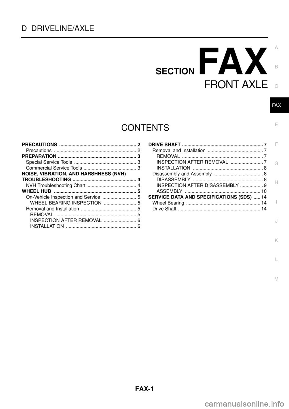
PRECAUTIONS .......................................................... 2
Precautions .............................................................. 2
PREPARATION ........................................................... 3
Special Service Tools ............................................... 3
Commercial Service Tools ........................................ 3
NOISE, VIBRATION, AND HARSHNESS (NVH)
TROUBLESHOOTING ................................................ 4
NVH Troubleshooting Chart ..................................... 4
WHEEL HUB .............................................................. 5
On-Vehicle Inspection and Service .......................... 5
WHEEL BEARING INSPECTION ......................... 5
Removal and Installation .......................................... 5
REMOVAL ............................................................. 5
INSPECTION AFTER REMOVAL ......................... 6
INSTALLATION ..................................................... 6DRIVE SHAFT ............................................................. 7
Removal and Installation .......................................... 7
REMOVAL ............................................................. 7
INSPECTION AFTER REMOVAL ......................... 7
INSTALLATION ..................................................... 8
Disassembly and Assembly ...................................... 8
DISASSEMBLY ..................................................... 8
INSPECTION AFTER DISASSEMBLY .................. 9
ASSEMBLY ......................................................... 10
SERVICE DATA AND SPECIFICATIONS (SDS) ...... 14
Wheel Bearing ........................................................ 14
Drive Shaft .............................................................. 14
Page 1535 of 3171
PREPARATION
FAX-3
C
E
F
G
H
I
J
K
L
MA
B
FA X
PREPARATIONPFP:00002
Special Service ToolsEDS003I4
Commercial Service ToolsEDS003I5
Tool number
Tool nameDescription
ST29020001
Gear arm pullerRemoving ball joint for steering knuckle
a: 34 mm (1.34 in)
b: 6.5 mm (0.256 in)
c: 61.5 mm (2.421 in)
KV38105500
ProtectorInstalling drive shaft
a: 40 mm (1.57 in) dia
KV40107300
BootbandcrimpingtoolInstalling boot bands
NT694
ZZA0835D
ZZA1229D
Tool nameDescription
PullerRemoving drive shaft
NT077