Page 1502 of 3171
EM-120
CYLINDER BLOCK
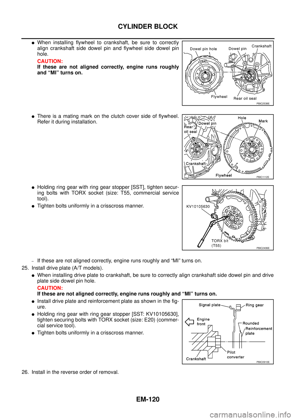
lWhen installing flywheel to crankshaft, be sure to correctly
align crankshaft side dowel pin and flywheel side dowel pin
hole.
CAUTION:
If these are not aligned correctly, engine runs roughly
and “MI” turns on.
lThere is a mating mark on the clutch cover side of flywheel.
Refer it during installation.
lHolding ring gear with ring gear stopper [SST], tighten secur-
ing bolts with TORX socket (size: T55, commercial service
tool).
lTighten bolts uniformly in a crisscross manner.
–If these are not aligned correctly, engine runs roughly and “MI” turns on.
25. Install drive plate (A/T models).
lWhen installing drive plate to crankshaft, be sure to correctly align crankshaft side dowel pin and drive
plate side dowel pin hole.
CAUTION:
If these are not aligned correctly, engine runs roughly and “MI” turns on.
lInstall drive plate and reinforcement plate as shown in the fig-
ure.
lHolding ring gear with ring gear stopper [SST: KV10105630],
tighten securing bolts with TORX socket (size: E20) (commer-
cial service tool).
lTighten bolts uniformly in a crisscross manner.
26. Install in the reverse order of removal.
PBIC2538E
PBIC1112E
PBIC2406E
PBIC0910E
Page 1503 of 3171
CYLINDER BLOCK
EM-121
C
D
E
F
G
H
I
J
K
L
MA
EM
How to Select Piston and BearingEBS01E6F
DESCRIPTION
lThe identification grade stamped on each part is the grade for the dimension measured in new condition.
This grade cannot apply to reused parts.
lFor reused or repaired parts, measure the dimension accurately. Determine the grade by comparing the
measurement with the values of each selection table.
lFor details of the measurement method of each part, the reuse standards and the selection method of the
selective fitting parts, refer to the text.
HOW TO SELECT PISTON
When Using New Cylinder Block
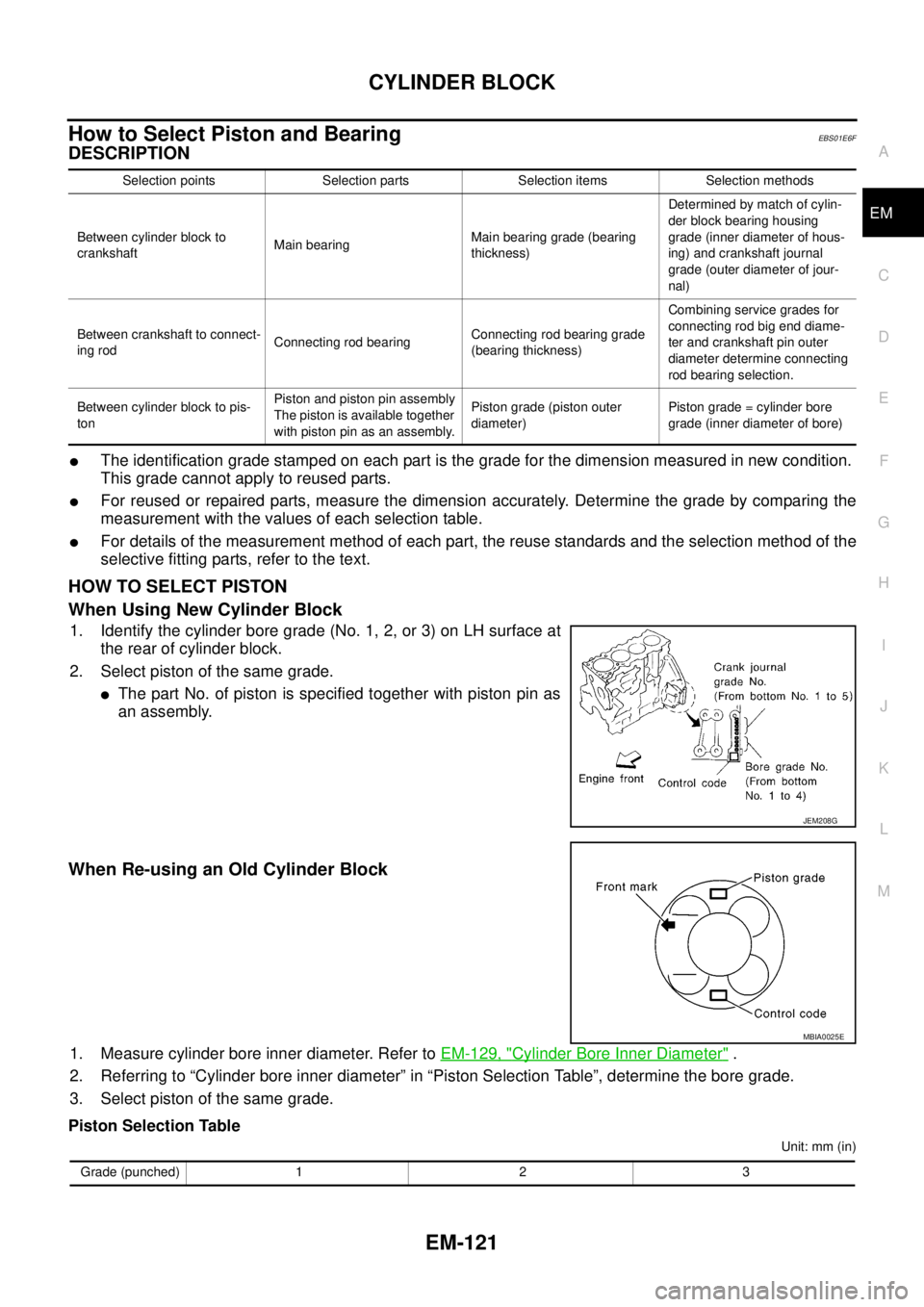
1. Identify the cylinder bore grade (No. 1, 2, or 3) on LH surface at
the rear of cylinder block.
2. Select piston of the same grade.
lThe part No. of piston is specified together with piston pin as
an assembly.
When Re-using an Old Cylinder Block
1. Measure cylinder bore inner diameter. Refer toEM-129, "Cylinder Bore Inner Diameter".
2. Referring to “Cylinder bore inner diameter” in “Piston Selection Table”, determine the bore grade.
3. Select piston of the same grade.
Piston Selection Table
Unit: mm (in) Selection points Selection parts Selection items Selection methods
Between cylinder block to
crankshaftMain bearingMain bearing grade (bearing
thickness)Determined by match of cylin-
der block bearing housing
grade (inner diameter of hous-
ing) and crankshaft journal
grade (outer diameter of jour-
nal)
Between crankshaft to connect-
ing rodConnecting rod bearingConnecting rod bearing grade
(bearing thickness)Combining service grades for
connecting rod big end diame-
ter and crankshaft pin outer
diameter determine connecting
rod bearing selection.
Between cylinder block to pis-
tonPiston and piston pin assembly
The piston is available together
with piston pin as an assembly.Piston grade (piston outer
diameter)Piston grade = cylinder bore
grade (inner diameter of bore)
JEM208G
MBIA0025E
Grade (punched) 1 2 3
Page 1517 of 3171
SERVICE DATA AND SPECIFICATIONS (SDS)
EM-135
C
D
E
F
G
H
I
J
K
L
MA
EM
SERVICE DATA AND SPECIFICATIONS (SDS)PFP:00030
Standard and LimitEBS01E6H
GENERAL SPECIFICATIONS
INTAKE MANIFOLD AND EXHAUST MANIFOLD
Unit: mm (in)
DRIVE BELTS
Belt Deflection:
*: When engine is cold.Cylinder arrangementIn-line 4
Displacement
Unit: cm
3(cu in)2,488 (151.82)
Bore and stroke Unit: mm (in) 89.0 x 100 (3.504 x 3.937)
Valve arrangementDOHC
Firing order1-3-4-2
Number of piston ringsCompression 2
Oil 1
Number of main bearings5
Compression ratio16.5
Compression pressure
Unit: kPa (bar, kg/cm
2, psi)/200 rpmStandard 3,100 (31, 31.6, 450)
Minimum 2,500 (25, 25.5, 363)
Differential limit between cylinders 490 (4.9, 5.0, 71)
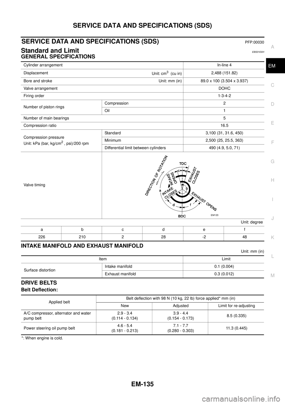
Valve timing
Unit: degree
abc de f
226 210 2 28 -2 48
EM120
Item Limit
Surface distortionIntake manifold 0.1 (0.004)
Exhaust manifold 0.3 (0.012)
Applied beltBelt deflection with 98 N (10 kg, 22 lb) force applied* mm (in)
New Adjusted Limit for re-adjusting
A/C compressor, alternator and water
pump belt2.9 - 3.4
(0.114 - 0.134)3.9 - 4.4
(0.154 - 0.173)8.5 (0.335)
Power steering oil pump belt4.6 - 5.4
(0.181 - 0.213)7.1 - 7.7
(0.280 - 0.303)11.3 (0.445)
Page 1518 of 3171
EM-136
SERVICE DATA AND SPECIFICATIONS (SDS)
CYLINDER HEAD
Unit: mm (in)
VA LV E
Valve Dimensions
Unit: mm (in)
Valve Clearance
Unit: mm (in)
*: Approximately 80°C (176°F) Item Standard Limit
Cylinder head distortion Less than 0.04 (0.0016) 0.1 (0.004)
JEM204G
Valve head diameter “D”Intake 28.0 - 28.3 (1.102 - 1.114)
Exhaust 26.0 - 26.3 (1.024 - 1.035)
Valve length “L”Intake 106.72 (4.2016)
Exhaust 106.36 (4.1874)
Valve stem diameter “d”Intake 5.965 - 5.980 (0.2348 - 0.2354)
Exhaust 5.945 - 5.960 (0.2341 - 0.2346)
Valve seat angle “a” Intake and exhaust 45 degrees 15¢- 45 degrees 45¢
Valvemargin“T”Intake 1.60 (0.0630)
Exhaust2WD models 1.80 (0.0709)
4WD models 1.48 (0.0583)
Valvemargin“T”limitMore than 1.0 (0.039)
Valve stem end surface grinding limit Less than 0.2 (0.008)
SEM188
Item Cold Hot* (Reference data)
Intake 0.24 - 0.32 (0.0094 - 0.0126) 0.274 - 0.386 (0.0108 - 0.0152)
Exhaust 0.26 - 0.34 (0.0102 - 0.0134) 0.308 - 0.432 (0.0121 - 0.0170)
Page 1519 of 3171
SERVICE DATA AND SPECIFICATIONS (SDS)
EM-137
C
D
E
F
G
H
I
J
K
L
MA
EM
Available Shims
Stamped mark Thickness mm (in)
2.10 2.10 (0.0827)
2.12 2.12 (0.0835)
2.14 2.14 (0.0843)
2.16 2.16 (0.0850)
2.18 2.18 (0.0858)
2.20 2.20 (0.0866)
2.22 2.22 (0.0874)
2.24 2.24 (0.0882)
2.26 2.26 (0.0890)
2.28 2.28 (0.0898)
2.30 2.30 (0.0906)
2.32 2.32 (0.0913)
2.34 2.34 (0.0921)
2.36 2.36 (0.0929)
2.38 2.38 (0.0937)
2.40 2.40 (0.0954)
2.42 2.42 (0.0953)
2.44 2.44 (0.0961)
2.46 2.46 (0.0969)
2.48 2.48 (0.0976)
2.50 2.50 (0.0984)
2.52 2.52 (0.0992)
2.54 2.54 (0.1000)
2.56 2.56 (0.1008)
2.58 2.58 (0.1016)
2.60 2.60 (0.1024)
2.62 2.62 (0.1031)
2.64 2.64 (0.1039)
2.66 2.66 (0.1047)
2.68 2.68 (0.1055)
2.70 2.70 (0.1063)
2.72 2.72 (0.1071)
2.74 2.74 (0.1079)
SEM512G
Page 1520 of 3171
EM-138
SERVICE DATA AND SPECIFICATIONS (SDS)
Valve Spring
Valve Lifter
Unit: mm (in)
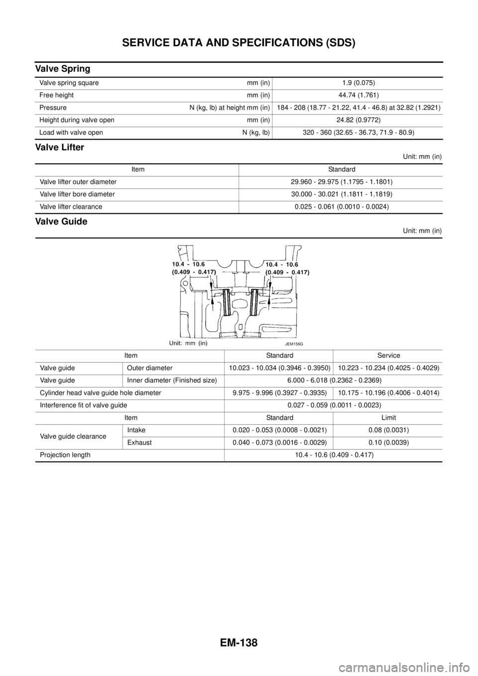
Valve Guide
Unit: mm (in) Valve spring square mm (in) 1.9 (0.075)
Free height mm (in) 44.74 (1.761)
Pressure N (kg, lb) at height mm (in) 184 - 208 (18.77 - 21.22, 41.4 - 46.8) at 32.82 (1.2921)
Height during valve open mm (in) 24.82 (0.9772)
Load with valve open N (kg, lb) 320 - 360 (32.65 - 36.73, 71.9 - 80.9)
Item Standard
Valve lifter outer diameter 29.960 - 29.975 (1.1795 - 1.1801)
Valve lifter bore diameter 30.000 - 30.021 (1.1811 - 1.1819)
Valve lifter clearance 0.025 - 0.061 (0.0010 - 0.0024)
Item Standard Service
Valve guide Outer diameter 10.023 - 10.034 (0.3946 - 0.3950) 10.223 - 10.234 (0.4025 - 0.4029)
Valve guide Inner diameter (Finished size) 6.000 - 6.018 (0.2362 - 0.2369)
Cylinder head valve guide hole diameter 9.975 - 9.996 (0.3927 - 0.3935) 10.175 - 10.196 (0.4006 - 0.4014)
Interference fit of valve guide 0.027 - 0.059 (0.0011 - 0.0023)
Item Standard Limit
Valve guide clearanceIntake 0.020 - 0.053 (0.0008 - 0.0021) 0.08 (0.0031)
Exhaust 0.040 - 0.073 (0.0016 - 0.0029) 0.10 (0.0039)
Projection length 10.4 - 10.6 (0.409 - 0.417)
JEM156G
Page 1521 of 3171
SERVICE DATA AND SPECIFICATIONS (SDS)
EM-139
C
D
E
F
G
H
I
J
K
L
MA
EM
Valve Seat
Unit: mm (in)
Items Standard Oversize [0.5 (0.02)] (Service)
Cylinder head seat (1) recess diam-
eter “D”Intake 30.000 - 30.016 (1.1811 - 1.1817) 30.500 - 30.516 (1.2008 - 1.2014)
Exhaust 29.000 - 29.016 (1.1417 - 1.1424) 29.500 - 29.516 (1.1614 - 1.1620)
Valve seat outer diameter “d”Intake (A) 30.080 - 30.100 (1.1842 - 1.1850) 30.580 - 30.600 (1.2039 - 1.2047)
Exhaust (B) 29.080 - 29.096 (1.1449 - 1.1455) 29.580 - 29.596 (1.1646 - 1.1652)
Valve seat interference fitIntake (A) 0.064 - 0.100 (0.0025 - 0.0039)
Exhaust (B) 0.064 - 0.096 (0.0025 - 0.0038)
Diameter “d1”Intake (A) 27.15 - 27.65 (1.0689 - 1.0886) 26.05 - 26.55 (1.0256 - 1.0453)
Exhaust (B) 24.95 - 25.45 (0.982 - 1.0020) 24.15 - 24.65 (0.9508 - 0.9705)
PBIC4054E
JEM253G
Page 1522 of 3171
EM-140
SERVICE DATA AND SPECIFICATIONS (SDS)
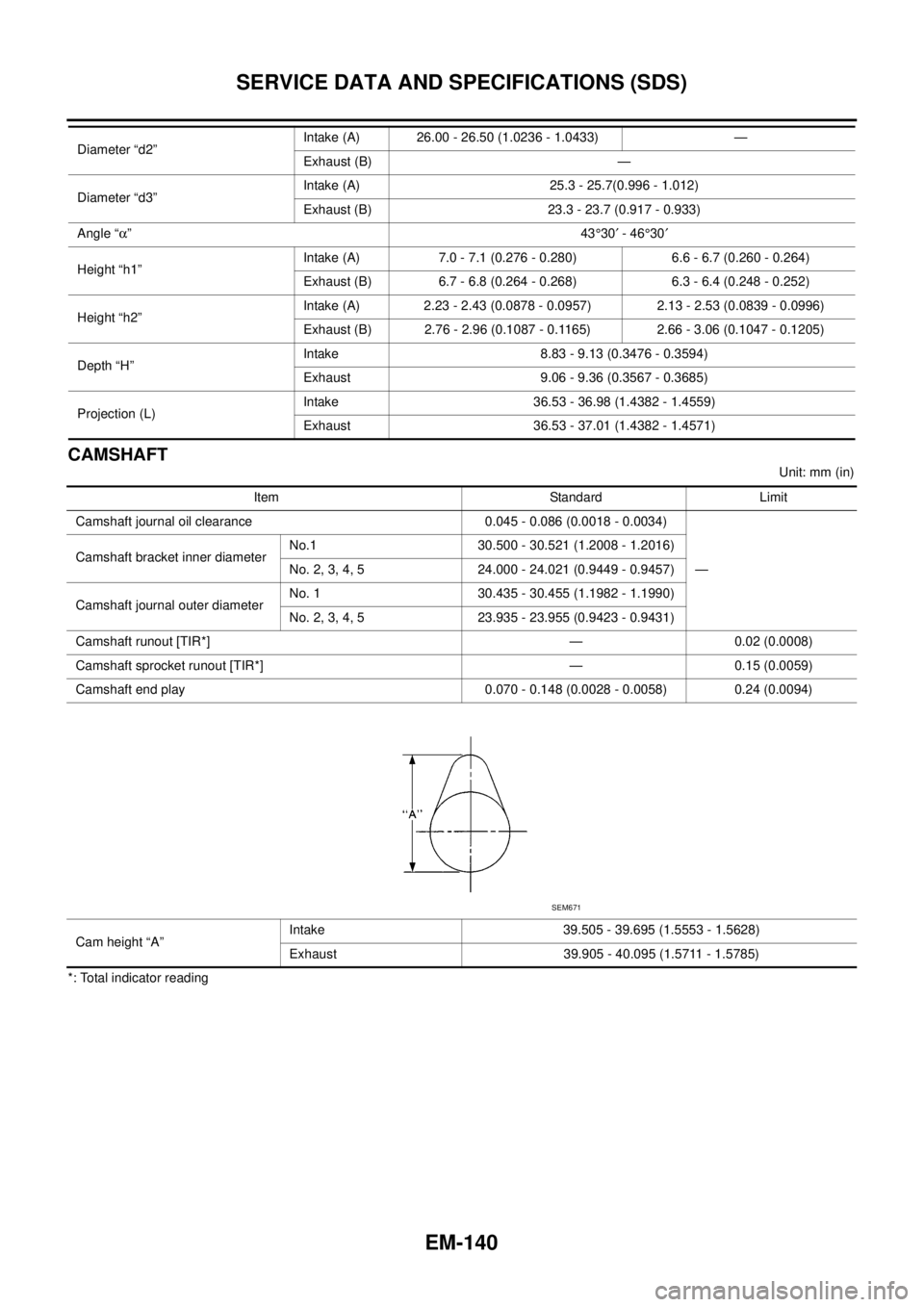
CAMSHAFT
Unit: mm (in)
*: Total indicator readingDiameter “d2”Intake (A) 26.00 - 26.50 (1.0236 - 1.0433) —
Exhaust (B) —
Diameter “d3”Intake (A) 25.3 - 25.7(0.996 - 1.012)
Exhaust (B) 23.3 - 23.7 (0.917 - 0.933)
Angle “a”43°30¢-46°30¢
Height “h1”Intake (A) 7.0 - 7.1 (0.276 - 0.280) 6.6 - 6.7 (0.260 - 0.264)
Exhaust (B) 6.7 - 6.8 (0.264 - 0.268) 6.3 - 6.4 (0.248 - 0.252)
Height “h2”Intake (A) 2.23 - 2.43 (0.0878 - 0.0957) 2.13 - 2.53 (0.0839 - 0.0996)
Exhaust (B) 2.76 - 2.96 (0.1087 - 0.1165) 2.66 - 3.06 (0.1047 - 0.1205)
Depth “H”Intake 8.83 - 9.13 (0.3476 - 0.3594)
Exhaust 9.06 - 9.36 (0.3567 - 0.3685)
Projection (L)Intake 36.53 - 36.98 (1.4382 - 1.4559)
Exhaust 36.53 - 37.01 (1.4382 - 1.4571)
Item Standard Limit
Camshaft journal oil clearance 0.045 - 0.086 (0.0018 - 0.0034)
— Camshaft bracket inner diameterNo.1 30.500 - 30.521 (1.2008 - 1.2016)
No. 2, 3, 4, 5 24.000 - 24.021 (0.9449 - 0.9457)
Camshaft journal outer diameterNo. 1 30.435 - 30.455 (1.1982 - 1.1990)
No. 2, 3, 4, 5 23.935 - 23.955 (0.9423 - 0.9431)
Camshaft runout [TIR*] — 0.02 (0.0008)
Camshaft sprocket runout [TIR*] — 0.15 (0.0059)
Camshaft end play 0.070 - 0.148 (0.0028 - 0.0058) 0.24 (0.0094)
Cam height “A”Intake 39.505 - 39.695 (1.5553 - 1.5628)
Exhaust 39.905 - 40.095 (1.5711 - 1.5785)
SEM671