Page 1604 of 3171
FSU-4
PREPARATION
Commercial Service Tools
EES002KJ
Tool nameDescription
Spring compressor Removing and installing coil spring
NT717
Page 1607 of 3171
ON-VEHICLE SERVICE
FSU-7
C
D
F
G
H
I
J
K
L
MA
B
FSU
ON-VEHICLE SERVICEPFP:00000
Front Suspension PartsEES002KM
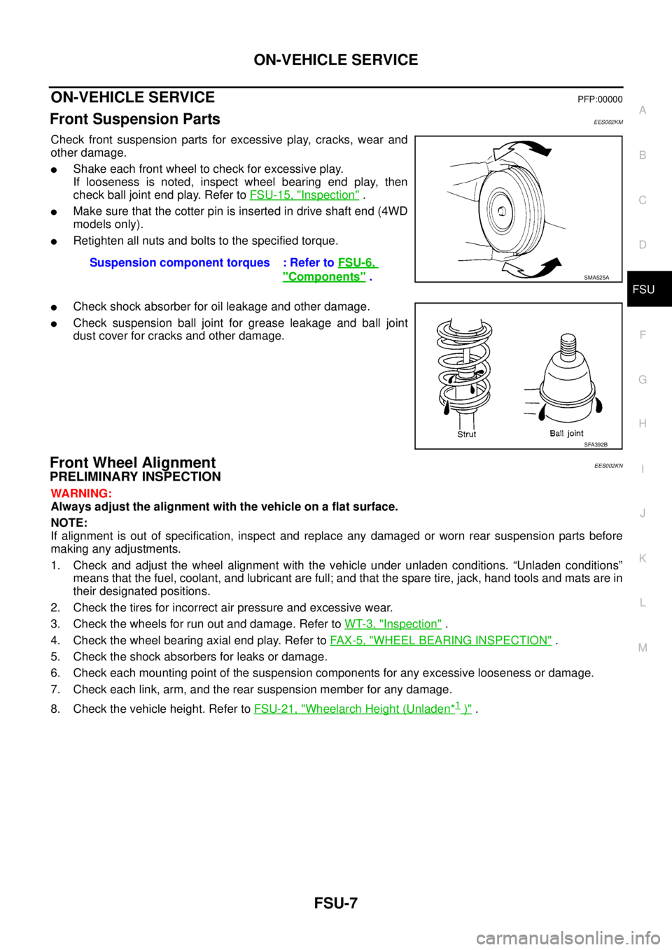
Check front suspension parts for excessive play, cracks, wear and
other damage.
lShake each front wheel to check for excessive play.
If looseness is noted, inspect wheel bearing end play, then
check ball joint end play. Refer toFSU-15, "
Inspection".
lMake sure that the cotter pin is inserted in drive shaft end (4WD
models only).
lRetighten all nuts and bolts to the specified torque.
lCheck shock absorber for oil leakage and other damage.
lCheck suspension ball joint for grease leakage and ball joint
dust cover for cracks and other damage.
Front Wheel AlignmentEES002KN
PRELIMINARY INSPECTION
WARNING:
Always adjust the alignment with the vehicle on a flat surface.
NOTE:
If alignment is out of specification, inspect and replace any damaged or worn rear suspension parts before
making any adjustments.
1. Check and adjust the wheel alignment with the vehicle under unladen conditions. “Unladen conditions”
means that the fuel, coolant, and lubricant are full; and that the spare tire, jack, hand tools and mats are in
their designated positions.
2. Check the tires for incorrect air pressure and excessive wear.
3. Check the wheels for run out and damage. Refer toWT-3, "
Inspection".
4. Check the wheel bearing axial end play. Refer toFA X - 5 , "
WHEEL BEARING INSPECTION".
5. Check the shock absorbers for leaks or damage.
6. Check each mounting point of the suspension components for any excessive looseness or damage.
7. Check each link, arm, and the rear suspension member for any damage.
8. Check the vehicle height. Refer toFSU-21, "
Wheelarch Height (Unladen*1)". Suspension component torques : Refer toFSU-6,
"Components".SMA525A
SFA392B
Page 1608 of 3171
FSU-8
ON-VEHICLE SERVICE
CAMBER AND CASTER
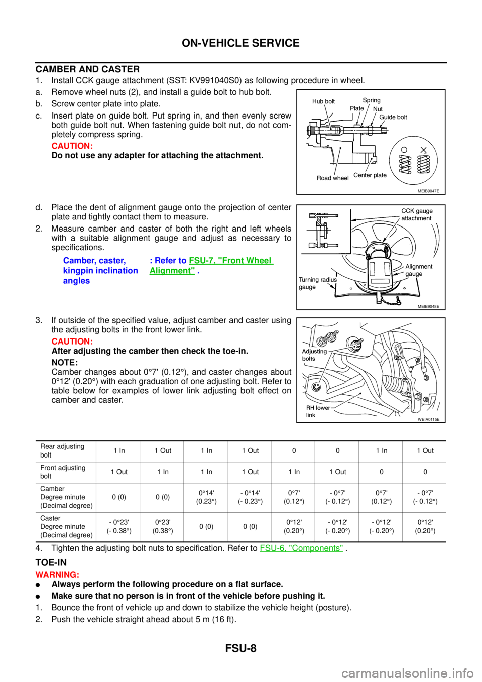
1. Install CCK gauge attachment (SST: KV991040S0) as following procedure in wheel.
a. Remove wheel nuts (2), and install a guide bolt to hub bolt.
b. Screw center plate into plate.
c. Insert plate on guide bolt. Put spring in, and then evenly screw
both guide bolt nut. When fastening guide bolt nut, do not com-
pletely compress spring.
CAUTION:
Do not use any adapter for attaching the attachment.
d. Place the dent of alignment gauge onto the projection of center
plate and tightly contact them to measure.
2. Measure camber and caster of both the right and left wheels
with a suitable alignment gauge and adjust as necessary to
specifications.
3. If outside of the specified value, adjust camber and caster using
the adjusting bolts in the front lower link.
CAUTION:
After adjusting the camber then check the toe-in.
NOTE:
Camber changes about 0°7' (0.12°), and caster changes about
0°12' (0.20°) with each graduation of one adjusting bolt. Refer to
table below for examples of lower link adjusting bolt effect on
camber and caster.
4. Tighten the adjusting bolt nuts to specification. Refer toFSU-6, "
Components".
TOE-IN
WARNING:
lAlways perform the following procedure on a flat surface.
lMake sure that no person is in front of the vehicle before pushing it.
1. Bounce the front of vehicle up and down to stabilize the vehicle height (posture).
2. Push the vehicle straight ahead about 5 m (16 ft).
MEIB9047E
Camber, caster,
kingpin inclination
angles:RefertoFSU-7, "Front Wheel
Alignment".
MEIB9048E
WEIA0115E
Rear adjusting
bolt1In 1Out 1In 1Out 0 0 1In 1Out
Front adjusting
bolt1Out 1In 1In 1Out 1In 1Out 0 0
Camber
Degree minute
(Decimal degree)0(0) 0(0)0°14'
(0.23°)-0°14'
(- 0.23°)0°7'
(0.12°)-0°7'
(- 0.12°)0°7'
(0.12°)-0°7'
(- 0.12°)
Caster
Degree minute
(Decimal degree)-0°23'
(- 0.38°)0°23'
(0.38°)0(0) 0(0)0°12'
(0.20°)-0°12'
(- 0.20°)-0°12'
(- 0.20°)0°12'
(0.20°)
Page 1609 of 3171
ON-VEHICLE SERVICE
FSU-9
C
D
F
G
H
I
J
K
L
MA
B
FSU
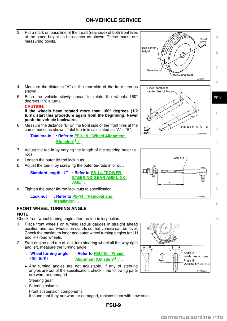
3. Put a mark on base line of the tread (rear side) of both front tires
at the same height as hub center as shown. These marks are
measuring points.
4. Measure the distance “A” on the rear side of the front tires as
shown.
5. Push the vehicle slowly ahead to rotate the wheels 180°
degrees (1/2 a turn).
CAUTION:
If the wheels have rotated more than 180°degrees (1/2
turn), start this procedure again from the beginning. Never
push the vehicle backward.
6. Measure the distance “B” on the front side of the front tires at the
same marks as shown. Total toe-in is calculated as “A” – “B”.
7. Adjust the toe-in by varying the length of the steering outer tie-
rods.
a. Loosen the outer tie-rod lock nuts.
b. Adjust the toe-in by screwing the outer tie-rods in or out.
c. Tighten the outer tie-rod lock nuts to specification.
FRONT WHEEL TURNING ANGLE
NOTE:
Check front wheel turning angle after the toe-in inspection.
1. Place front wheels on turning radius gauges in straight ahead
position and rear wheels on stands so that vehicle can be level.
Check the maximum inner and outer wheel turning angles for LH
and RH road wheels.
2. Start engine and run at idle, turn steering wheel all the way right
and left, measure the turning angle.
lAny turning angles are not adjustable. If any of steering
angles are out of the specification, check if the following parts
are worn or damaged.
–Steering gear
–Steering column
–Front suspension components
If found that they are worn or damaged, replace them with new ones.
AFA050
Total toe-in : Refer toFSU-19, "Wheel Alignment
(Unladen*1)".
SFA234AC
Standard length “L” : Refer toPS-14, "POWER
STEERING GEAR AND LINK-
AGE".
Lock nut : Refer toPS-14, "
Removal and
Installation".
SFA486A
Wheel turning angle
(full turn):RefertoFSU-19, "Wheel
Alignment (Unladen*1)".
SFA439BA
Page 1610 of 3171
FSU-10
COIL SPRING AND SHOCK ABSORBER
COIL SPRING AND SHOCK ABSORBER
PFP:56210
Removal and InstallationEES002KO
REMOVAL
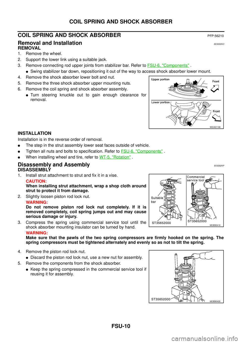
1. Remove the wheel.
2. Support the lower link using a suitable jack.
3. Remove connecting rod upper joints from stabilizer bar. Refer toFSU-6, "
Components".
lSwing stabilizer bar down, repositioning it out of the way to access shock absorber lower mount.
4. Remove the shock absorber lower bolt and nut.
5. Remove the three shock absorber upper mounting nuts.
6. Remove the coil spring and shock absorber assembly.
lTurn steering knuckle out to gain enough clearance for
removal.
INSTALLATION
Installation is in the reverse order of removal.
lThe step in the strut assembly lower seat faces outside of vehicle.
lTighten all nuts and bolts to specification. Refer toFSU-6, "Components".
lWhen installing wheel and tire, refer toWT-5, "Rotation".
Disassembly and AssemblyEES002KP
DISASSEMBLY
1. Install strut attachment to strut and fix it in a vise.
CAUTION:
When installing strut attachment, wrap a shop cloth around
strut to protect it from damage.
2. Slightly loosen piston rod lock nut.
WARNING:
Do not remove piston rod lock nut completely. If it is
removed completely, coil spring jumps out and may cause
serious damage or injury.
3. Compress the spring using commercial service tool until the
shock absorber mounting insulator can be turned by hand.
WARNING:
Make sure that the pawls of the two spring compressors are firmly hooked on the spring. The
spring compressors must be tightened alternately and evenly so as not to tilt the spring.
4. Remove the piston rod lock nut.
lDiscard the piston rod lock nut, use a new nut for assembly.
5. Remove the components from the shock absorber.
lKeep the spring compressed in the commercial service tool if
reusing it for assembly.
WEIA0116E
MEIB9041E
MEIB9042E
Page 1616 of 3171
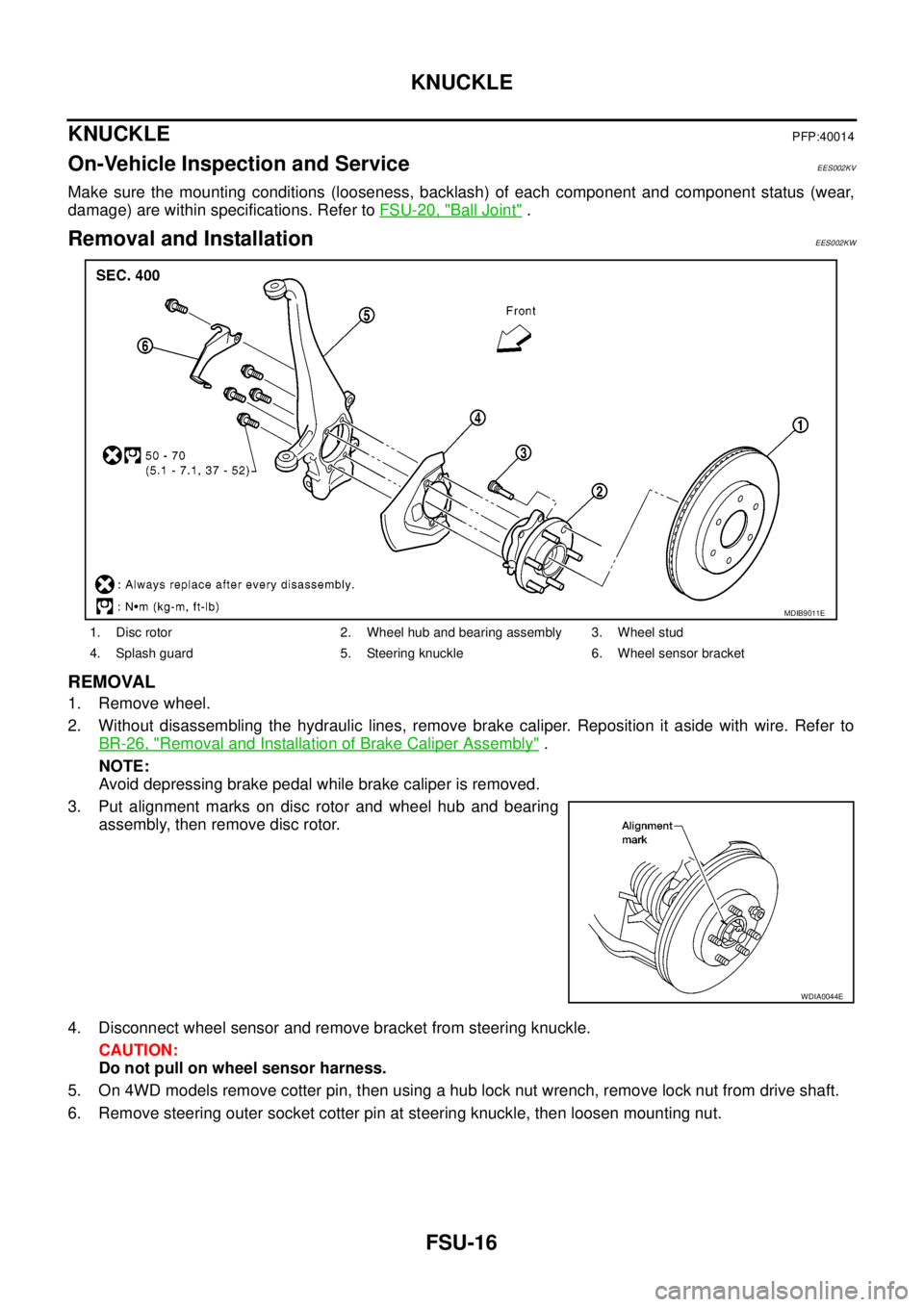
FSU-16
KNUCKLE
KNUCKLE
PFP:40014
On-Vehicle Inspection and ServiceEES002KV
Make sure the mounting conditions (looseness, backlash) of each component and component status (wear,
damage) are within specifications. Refer toFSU-20, "
Ball Joint".
Removal and InstallationEES002KW
REMOVAL
1. Remove wheel.
2. Without disassembling the hydraulic lines, remove brake caliper. Reposition it aside with wire. Refer to
BR-26, "
Removal and Installation of Brake Caliper Assembly".
NOTE:
Avoid depressing brake pedal while brake caliper is removed.
3. Put alignment marks on disc rotor and wheel hub and bearing
assembly, then remove disc rotor.
4. Disconnect wheel sensor and remove bracket from steering knuckle.
CAUTION:
Do not pull on wheel sensor harness.
5. On 4WD models remove cotter pin, then using a hub lock nut wrench, remove lock nut from drive shaft.
6. Remove steering outer socket cotter pin at steering knuckle, then loosen mounting nut.
1. Disc rotor 2. Wheel hub and bearing assembly 3. Wheel stud
4. Splash guard 5. Steering knuckle 6. Wheel sensor bracket
MDIB9011E
WDIA0044E
Page 1619 of 3171
SERVICE DATA AND SPECIFICATIONS (SDS)
FSU-19
C
D
F
G
H
I
J
K
L
MA
B
FSU
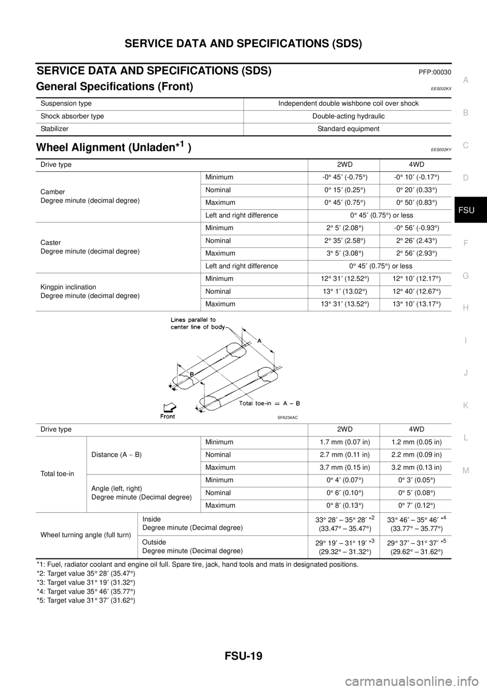
SERVICE DATA AND SPECIFICATIONS (SDS)PFP:00030
General Specifications (Front)EES002KX
Wheel Alignment (Unladen*1)EES002KY
*1: Fuel, radiator coolant and engine oil full. Spare tire, jack, hand tools and mats in designated positions.
*2: Target value 35°28¢(35.47°)
*3: Target value 31°19¢(31.32°)
*4: Target value 35°46¢(35.77°)
*5: Target value 31°37¢(31.62°) Suspension type Independent double wishbone coil over shock
Shock absorber type Double-acting hydraulic
StabilizerStandard equipment
Drive type2WD 4WD
Camber
Degree minute (decimal degree)Minimum -0°45¢(-0.75°)-0°10¢(-0.17°)
Nominal 0°15¢(0.25°)0°20¢(0.33°)
Maximum 0°45¢(0.75°)0°50¢(0.83°)
Left and right difference 0°45¢(0.75°)orless
Caster
Degree minute (decimal degree)Minimum 2°5¢(2.08°)-0°56¢(-0.93°)
Nominal 2°35¢(2.58°)2°26¢(2.43°)
Maximum 3°5¢(3.08°)2°56¢(2.93°)
Left and right difference 0°45¢(0.75°)orless
Kingpin inclination
Degree minute (decimal degree)Minimum 12°31¢(12.52°)12°10¢(12.17°)
Nominal 13°1¢(13.02°)12°40¢(12.67°)
Maximum 13°31¢(13.52°)13°10¢(13.17°)
Drive type2WD 4WD
Total toe-inDistance (A-B)Minimum 1.7 mm (0.07 in) 1.2 mm (0.05 in)
Nominal 2.7 mm (0.11 in) 2.2 mm (0.09 in)
Maximum 3.7 mm (0.15 in) 3.2 mm (0.13 in)
Angle (left, right)
Degree minute (Decimal degree)Minimum 0°4¢(0.07°)0°3¢(0.05°)
Nominal 0°6¢(0.10°)0°5¢(0.08°)
Maximum 0°8¢(0.13°)0°7¢(0.12°)
Wheel turning angle (full turn)Inside
Degree minute (Decimal degree)33°28¢–35°28¢*
2
(33.47°– 35.47°)33°46¢–35°46¢*
4
(33.77°– 35.77°)
Outside
Degree minute (Decimal degree)29°19¢–31°19¢*
3
(29.32°– 31.32°)29°37¢–31°37¢*
5
(29.62°– 31.62°)
SFA234AC
Page 1620 of 3171
FSU-20
SERVICE DATA AND SPECIFICATIONS (SDS)
Ball Joint
EES002KZ
Swinging force “A” 7.8 - 54.9 N (0.8 - 5.6 kg-f, 1.8 - 12.3 lb-f)
Turning torque “B” 0.49 - 3.43 N·m (0.05 - 0.35 kg-m, 4 - 30 in-lb)
Vertical end play “C”0mm(0in)
SFA858A