Page 1585 of 3171

FL-1
FUEL SYSTEM
B ENGINE
CONTENTS
C
D
E
F
G
H
I
J
K
L
M
SECTIONFL
A
FL
FUEL SYSTEM
PREPARATION ........................................................... 2
Commercial Service Tools ........................................ 2
FUEL SYSTEM ........................................................... 3
Checking Fuel Lines ................................................. 3
General Precautions ................................................ 3
FUEL FILTER .............................................................. 4
Components ............................................................. 4
Removal and Installation .......................................... 4
REMOVAL ............................................................. 4
INSTALLATION ..................................................... 5
INSPECTION AFTER INSTALLATION ................. 5
Air Bleeding .............................................................. 5
Draining Water from Fuel Filter ................................ 6
FUEL COOLER .......................................................... 7
Components (4WD Models Only) ............................ 7
Removal and Installation (4WD Models Only) ......... 7
REMOVAL ............................................................. 7
INSTALLATION ..................................................... 8
INSPECTION AFTER INSTALLATION ................. 8FUEL TANK ................................................................ 9
Components ............................................................. 9
Removal and Installation .......................................... 9
REMOVAL ............................................................. 9
INSTALLATION ................................................... 12
INSPECTION AFTER INSTALLATION ................ 13
FUEL LEVEL SENSOR UNIT ................................... 14
Components ........................................................... 14
Removal and Installation ........................................ 14
REMOVAL ........................................................... 14
INSPECTION AFTER REMOVAL ....................... 14
INSTALLATION ................................................... 15
INSPECTION AFTER INSTALLATION ................ 15
SERVICE DATA AND SPECIFICATIONS (SDS) ...... 16
Standard and Limit .................................................. 16
Page 1586 of 3171
FL-2
PREPARATION
PREPARATION
PFP:00002
Commercial Service ToolsEBS01E70
Tool nameDescription
Fuel filter wrench Removing fuel filter
Fuel tank lock ring wrench Removing and installing fuel tank lock ring
PBIC0519E
ZZA0122D
Page 1589 of 3171

FUEL FILTER
FL-5
C
D
E
F
G
H
I
J
K
L
MA
FL
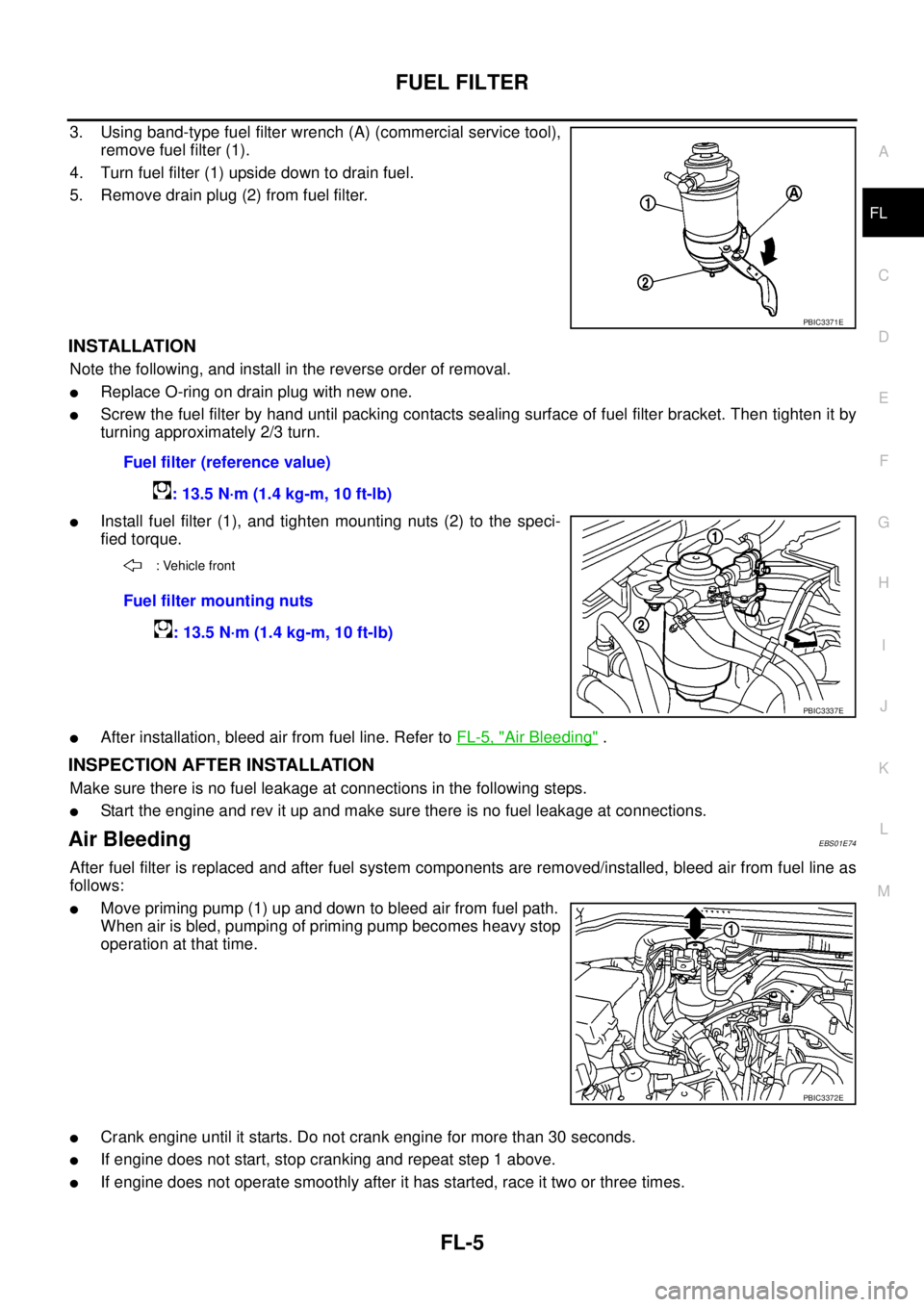
3. Using band-type fuel filter wrench (A) (commercial service tool),
remove fuel filter (1).
4. Turn fuel filter (1) upside down to drain fuel.
5. Remove drain plug (2) from fuel filter.
INSTALLATION
Note the following, and install in the reverse order of removal.
lReplace O-ring on drain plug with new one.
lScrew the fuel filter by hand until packing contacts sealing surface of fuel filter bracket. Then tighten it by
turning approximately 2/3 turn.
lInstall fuel filter (1), and tighten mounting nuts (2) to the speci-
fied torque.
lAfter installation, bleed air from fuel line. Refer toFL-5, "Air Bleeding".
INSPECTION AFTER INSTALLATION
Make sure there is no fuel leakage at connections in the following steps.
lStart the engine and rev it up and make sure there is no fuel leakage at connections.
Air BleedingEBS01E74
After fuel filter is replaced and after fuel system components are removed/installed, bleed air from fuel line as
follows:
lMove priming pump (1) up and down to bleed air from fuel path.
When air is bled, pumping of priming pump becomes heavy stop
operation at that time.
lCrank engine until it starts. Do not crank engine for more than 30 seconds.
lIf engine does not start, stop cranking and repeat step 1 above.
lIf engine does not operate smoothly after it has started, race it two or three times.
PBIC3371E
Fuel filter (reference value)
: 13.5 N·m (1.4 kg-m, 10 ft-lb)
: Vehicle front
Fuel filter mounting nuts
: 13.5 N·m (1.4 kg-m, 10 ft-lb)
PBIC3337E
PBIC3372E
Page 1598 of 3171
FL-14
FUEL LEVEL SENSOR UNIT
FUEL LEVEL SENSOR UNIT
PFP:17042
ComponentsEBS01F6N
lRefer toGI-10, "Components"for symbol marks in the figure.
Removal and InstallationEBS01E76
REMOVAL
WARNING:
Be sure to read “General Precautions” when working on fuel system. Refer toFL-3, "
General Precau-
tions".
1. Remove fuel tank from the vehicle. Refer toFL-9, "
FUEL TANK".
2. Using a fuel tank lock ring wrench (commercial service tool),
remove the lock ring.
3. Remove fuel level sensor unit.
CAUTION:
lDo not bend the float arm during removal.
lAvoid impacts such as falling when handling components.
INSPECTION AFTER REMOVAL
Make sure fuel level sensor unit is free from foreign materials. If any are found, remove them.
1. Lock ring 2. Fuel level sensor unit 3. Seal packing
4. Fuel tank
A. Refer to text.
PBIC3374E
PBIC0240E
Page 1599 of 3171
FUEL LEVEL SENSOR UNIT
FL-15
C
D
E
F
G
H
I
J
K
L
MA
FL
INSTALLATION
Note the following, and install in the reverse order of removal.
lInstall fuel level sensor unit (1) with aligning mating marks (A) on
fuel tank and fuel level sensor unit as shown in the figure.
lInstall lock ring (1), and tighten lock ring by hand. Then tighten
lock ring with a fuel tank lock ring wrench (commercial service
tool), aligning mating marks (A) on fuel tank and lock ring as
showninthefigure.
INSPECTION AFTER INSTALLATION
Make sure there is no fuel leakage at connections in the following steps.
lStart engine and rev it up and make sure there is no fuel leakage at connections.
: Vehicle front
PBIC3506E
: Vehicle front
PBIC3632E
Page 1600 of 3171
FL-16
SERVICE DATA AND SPECIFICATIONS (SDS)
SERVICE DATA AND SPECIFICATIONS (SDS)
PFP:00030
Standard and LimitEBS01E78
Fuel tank capacity
Approx. 80 (17-5/8 Imp gal)
Fuel recommendation Refer toGI-6
.
Page 1601 of 3171

FSU-1
FRONT SUSPENSION
E SUSPENSION
CONTENTS
C
D
F
G
H
I
J
K
L
M
SECTIONFSU
A
B
FSU
FRONT SUSPENSION
PRECAUTIONS .......................................................... 2
Precautions .............................................................. 2
PREPARATION ........................................................... 3
Special Service Tools ............................................... 3
Commercial Service Tools ........................................ 4
NOISE, VIBRATION, AND HARSHNESS (NVH)
TROUBLESHOOTING ................................................ 5
NVH Troubleshooting Chart ..................................... 5
FRONT SUSPENSION ASSEMBLY ........................... 6
Components ............................................................. 6
ON-VEHICLE SERVICE ............................................. 7
Front Suspension Parts ............................................ 7
Front Wheel Alignment ............................................. 7
PRELIMINARY INSPECTION ............................... 7
CAMBER AND CASTER ....................................... 8
TOE-IN .................................................................. 8
FRONT WHEEL TURNING ANGLE ..................... 9
COIL SPRING AND SHOCK ABSORBER ............... 10
Removal and Installation ........................................ 10
REMOVAL ........................................................... 10
INSTALLATION ................................................... 10
Disassembly and Assembly ................................... 10
DISASSEMBLY ................................................... 10
INSPECTION AFTER DISASSEMBLY ................ 11
ASSEMBLY .......................................................... 11
STABILIZER BAR ..................................................... 12
Removal and Installation ........................................ 12
REMOVAL ........................................................... 12
INSPECTION AFTER REMOVAL ....................... 12
INSTALLATION ................................................... 12UPPER LINK ............................................................. 13
Removal and Installation ........................................ 13
REMOVAL ........................................................... 13
INSPECTION AFTER REMOVAL ....................... 13
INSTALLATION ................................................... 13
LOWER LINK ............................................................ 14
Removal and Installation ........................................ 14
REMOVAL ........................................................... 14
INSPECTION AFTER REMOVAL ....................... 14
INSTALLATION ................................................... 14
UPPER BALL JOINT AND LOWER BALL JOINT ... 15
Removal and Installation ........................................ 15
Inspection ............................................................... 15
SWINGING FORCE ............................................ 15
TURNING FORCE .............................................. 15
VERTICAL END PLAY ........................................ 15
KNUCKLE ................................................................. 16
On-Vehicle Inspection and Service ......................... 16
Removal and Installation ........................................ 16
REMOVAL ........................................................... 16
INSPECTION AFTER REMOVAL ....................... 17
INSTALLATION ................................................... 18
SERVICE DATA AND SPECIFICATIONS (SDS) ...... 19
General Specifications (Front) ................................ 19
Wheel Alignment (Unladen*
1) ................................ 19
Ball Joint ................................................................. 20
Wheelarch Height (Unladen*
1) .............................. 21
Page 1603 of 3171
PREPARATION
FSU-3
C
D
F
G
H
I
J
K
L
MA
B
FSU
PREPARATIONPFP:00002
Special Service ToolsEES002KI
Tool number
Tool nameDescription
ST29020001
Gear arm pullerRemoving ball joint for knuckle
a: 34 mm (1.34 in)
b: 6.5 mm (0.256 in)
c: 61.5 mm (2.421 in)
HT72520000
Ball joint removerRemoving tie-rod outer end
ST35652000
Strut attachmentDisassembling and assembling strut
KV991040S0
CCK gauge attachment
1. Plate
2. Guide bolts
3. Nuts
4. Springs
5. Center plate
6. KV9910 4020 Adapter A
a: 72 mm (2.83 in) dia.
7. KV9910 4030 Adapter B
b: 65 mm (2.56 in) dia.
8. KV9910 4040 Adapter C
c: 57 mm (2.24 in) dia.
9. KV9910 4050 Adapter D
d: 53.4 mm (2.102 in) dia.Measuring wheel alignment
NT694
NT146
ZZA0807D
S-NT498