Page 3012 of 3171

TROUBLE DIAGNOSIS
TF-45
C
E
F
G
H
I
J
K
L
MA
B
TF
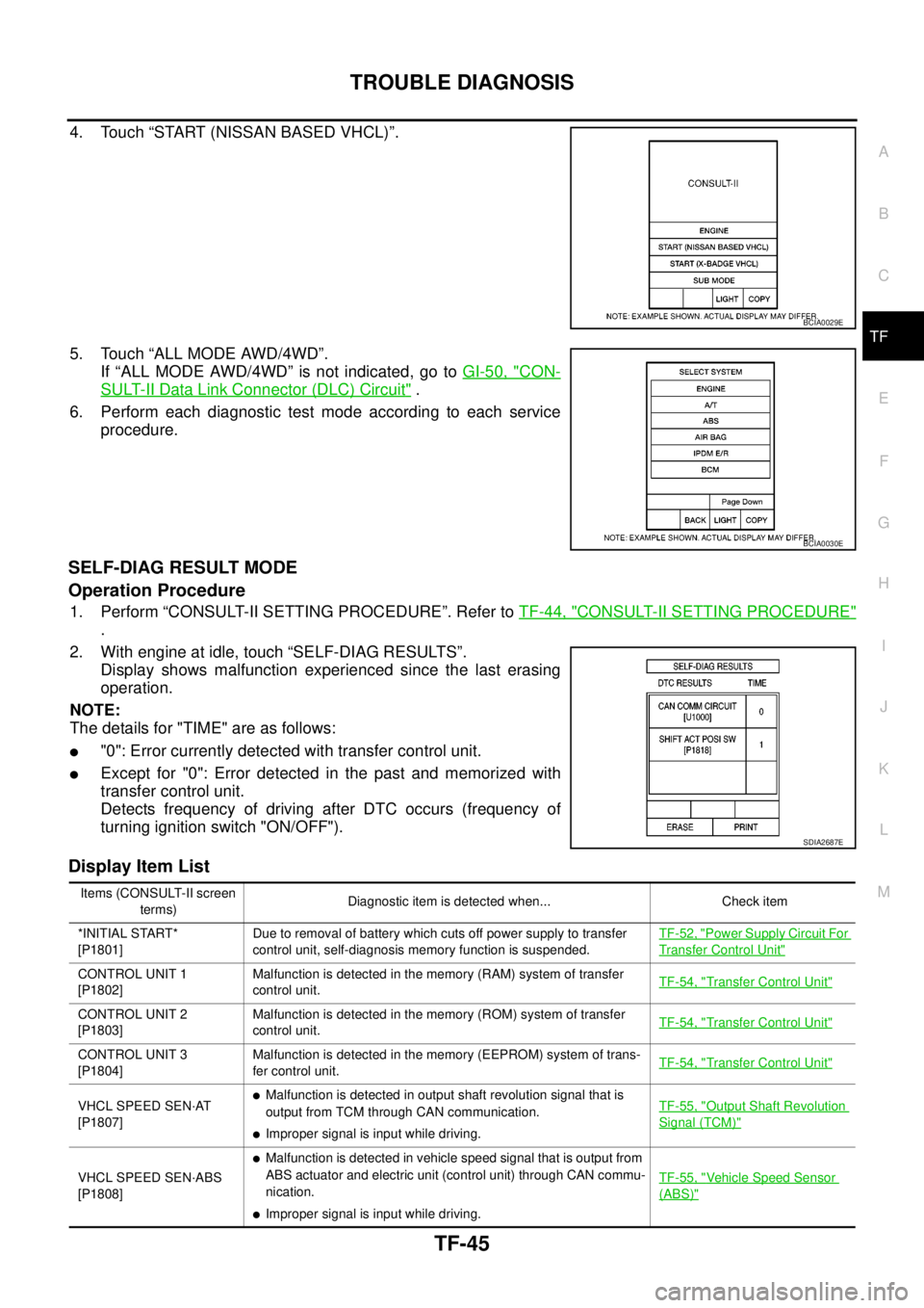
4. Touch “START (NISSAN BASED VHCL)”.
5. Touch “ALL MODE AWD/4WD”.
If “ALL MODE AWD/4WD” is not indicated, go toGI-50, "
CON-
SULT-II Data Link Connector (DLC) Circuit".
6. Perform each diagnostic test mode according to each service
procedure.
SELF-DIAG RESULT MODE
Operation Procedure
1. Perform “CONSULT-II SETTING PROCEDURE”. Refer toTF-44, "CONSULT-II SETTING PROCEDURE"
.
2. With engine at idle, touch “SELF-DIAG RESULTS”.
Display shows malfunction experienced since the last erasing
operation.
NOTE:
The details for "TIME" are as follows:
l"0": Error currently detected with transfer control unit.
lExcept for "0": Error detected in the past and memorized with
transfer control unit.
Detects frequency of driving after DTC occurs (frequency of
turning ignition switch "ON/OFF").
Display Item List
BCIA0029E
BCIA0030E
SDIA2687E
Items (CONSULT-II screen
terms)Diagnostic item is detected when... Check item
*INITIAL START*
[P1801]Due to removal of battery which cuts off power supply to transfer
control unit, self-diagnosis memory function is suspended.TF-52, "
Power Supply Circuit For
Transfer Control Unit"
CONTROL UNIT 1
[P1802]Malfunction is detected in the memory (RAM) system of transfer
control unit.TF-54, "Transfer Control Unit"
CONTROL UNIT 2
[P1803]Malfunction is detected in the memory (ROM) system of transfer
control unit.TF-54, "Transfer Control Unit"
CONTROL UNIT 3
[P1804]Malfunction is detected in the memory (EEPROM) system of trans-
fer control unit.TF-54, "Transfer Control Unit"
VHCL SPEED SEN·AT
[P1807]lMalfunction is detected in output shaft revolution signal that is
output from TCM through CAN communication.
lImproper signal is input while driving.TF-55, "
Output Shaft Revolution
Signal (TCM)"
VHCL SPEED SEN·ABS
[P1808]
lMalfunction is detected in vehicle speed signal that is output from
ABS actuator and electric unit (control unit) through CAN commu-
nication.
lImproper signal is input while driving.TF-55, "
Vehicle Speed Sensor
(ABS)"
Page 3105 of 3171
TF-138
SERVICE DATA AND SPECIFICATIONS (SDS)
SERVICE DATA AND SPECIFICATIONS (SDS)
PFP:00030
General SpecificationsEDS0032T
Inspection and AdjustmentEDS0032U
PINION GEAR END PLAY
Unit: mm (in)
CLEARANCE BETWEEN SHIFT FORK AND SLEEVE
Unit: mm (in) Applied modelYD25DDTi
Transfer modelTX15B
Fluid capacity (Approx.)
(lmp qt)2.0 (1-3/4)
Gear ratioHigh 1.000
Low 2.625
Number of teethPlanetary
gearSun gear 56
Internal gear 91
Front drive sprocket 38
Front drive shaft 38
Item Standard
Pinion gear end play 0.1 - 0.7 (0.004 - 0.028)
Item Standard
2-4 shift fork to 2-4 sleeve Less than 0.46 (0.018)
L-H shift fork to L-H sleeve Less than 0.46 (0.018)
Page 3106 of 3171

WT-1
ROAD WHEELS & TIRES
E SUSPENSION
CONTENTS
C
D
F
G
H
I
J
K
L
M
SECTIONWT
A
B
WT
ROAD WHEELS & TIRES
NOISE, VIBRATION, AND HARSHNESS (NVH)
TROUBLESHOOTING ................................................ 2
NVH Troubleshooting Chart ..................................... 2
WHEEL ....................................................................... 3
Inspection ................................................................. 3
STEEL WHEEL ..................................................... 3
WHEEL AND TIRE ASSEMBLY ................................. 4Balancing Wheels ..................................................... 4
REMOVAL ............................................................. 4
WHEEL BALANCE ADJUSTMENT ....................... 4
Rotation .................................................................... 5
SERVICE DATA AND SPECIFICATIONS (SDS) ........ 6
Road Wheel .............................................................. 6
Tire ........................................................................... 6
Page 3108 of 3171

WHEEL
WT-3
C
D
F
G
H
I
J
K
L
MA
B
WT
WHEELPFP:40300
InspectionEES002L2
1. Check tires for wear and improper inflation.
2. Check wheels for deformation, cracks and other damage. If
deformed, remove wheel and check wheel runout.
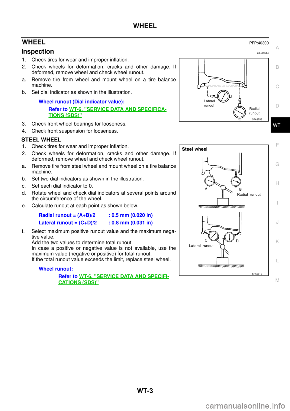
a. Remove tire from wheel and mount wheel on a tire balance
machine.
b. Set dial indicator as shown in the illustration.
3. Check front wheel bearings for looseness.
4. Check front suspension for looseness.
STEEL WHEEL
1. Check tires for wear and improper inflation.
2. Check wheels for deformation, cracks and other damage. If
deformed, remove wheel and check wheel runout.
a. Remove tire from steel wheel and mount wheel on a tire balance
machine.
b. Set two dial indicators as shown in the illustration.
c. Set each dial indicator to 0.
d. Rotate wheel and check dial indicators at several points around
the circumference of the wheel.
e. Calculate runout at each point as shown below.
f. Select maximum positive runout value and the maximum nega-
tive value.
Add the two values to determine total runout.
In case a positive or negative value is not available, use the
maximum value (negative or positive) for total runout.
If the total runout value exceeds the limit, replace steel wheel.Wheel runout (Dial indicator value):
Refer toWT-6, "
SERVICE DATA AND SPECIFICA-
TIONS (SDS)"SFA975B
Radial runout = (A+B)/2 : 0.5 mm (0.020 in)
Lateral runout = (C+D)/2 : 0.8 mm (0.031 in)
Wheel runout:
Refer toWT-6, "
SERVICE DATA AND SPECIFI-
CATIONS (SDS)"
SFA981B
Page 3110 of 3171

WHEEL AND TIRE ASSEMBLY
WT-5
C
D
F
G
H
I
J
K
L
MA
B
WT
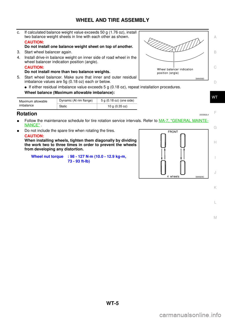
c. If calculated balance weight value exceeds 50 g (1.76 oz), install
two balance weight sheets in line with each other as shown.
CAUTION:
Do not install one balance weight sheet on top of another.
3. Start wheel balancer again.
4. Install drive-in balance weight on inner side of road wheel in the
wheel balancer indication position (angle).
CAUTION:
Do not install more than two balance weights.
5. Start wheel balancer. Make sure that inner and outer residual
imbalance values are 5g (0.18 oz) each or below.
lIf either residual imbalance value exceeds 5 g (0.18 oz), repeat installation procedures.
Wheel balance (Maximum allowable imbalance):
RotationEES002L4
lFollow the maintenance schedule for tire rotation service intervals. Refer toMA-7, "GENERAL MAINTE-
NANCE".
lDo not include the spare tire when rotating the tires.
CAUTION:
When installing wheels, tighten them diagonally by dividing
the work two to three times in order to prevent the wheels
from developing any distortion.
Maximum allowable
imbalanceDynamic (At rim flange) 5 g (0.18 oz) (one side)
Static 10 g (0.35 oz)
SMA056D
Wheel nut torque : 98 - 127 N·m (10.0 - 12.9 kg-m,
73 - 93 ft-lb)
SMA829C
Page 3111 of 3171
WT-6
SERVICE DATA AND SPECIFICATIONS (SDS)
SERVICE DATA AND SPECIFICATIONS (SDS)
PFP:00030
Road WheelEES002L5
TireEES002L6
Unit: kPa (kg/cm2, psi) Wheel type AluminumSteel
Inside Outside
Maximum radial
runout limitLateral mm (in) 0.3 (0.012) or less 1.0 (0.039) or less 0.9 (0.035) or less
Radial mm (in) 0.3 (0.012) or less 0.8 (0.031) or less 0.4 (0.016) or less
Maximum residual
imbalanceDynamic
(at rim flange)Less than 5 g (0.18 oz) (per side)
Static (at rim flange) Less than 10 g (0.35 oz)
Tire sizeAir pressure
Conventional tire Spare tire
Full size spare tire — 240 (2.4, 35)
235/70R16 240 (2.4, 35) —
255/70R16 240 (2.4, 35) —
265/70R16 240 (2.4, 35) —
255/65R17 240 (2.4, 35) —
Page 3114 of 3171

PRECAUTION
WW-3
C
D
E
F
G
H
I
J
L
MA
B
WW
PRECAUTIONPFP:00011
Precautions for Supplemental Restraint System (SRS) “AIR BAG” and “SEAT
BELT PRE-TENSIONER”
EKS00N1N
The Supplemental Restraint System such as “AIR BAG” and “SEAT BELT PRE-TENSIONER”, used along
with a front seat belt, helps to reduce the risk or severity of injury to the driver and front passenger for certain
types of collision. Information necessary to service the system safely is included in the SRS and SB section of
this Service Manual.
WARNING:
lTo avoid rendering the SRS inoperative, which could increase the risk of personal injury or death
in the event of a collision which would result in air bag inflation, all maintenance must be per-
formed by an authorized NISSAN/INFINITI dealer.
lImproper maintenance, including incorrect removal and installation of the SRS, can lead to per-
sonal injury caused by unintentional activation of the system. For removal of Spiral Cable and Air
Bag Module, see the SRS section.
lDo not use electrical test equipment on any circuit related to the SRS unless instructed to in this
Service Manual. SRS wiring harnesses can be identified by yellow and/or orange harnesses or
harness connectors.
Wiring Diagrams and Trouble DiagnosisEKS00L9V
When you read wiring diagrams, refer to the following:
lRefer toGI-15, "HowtoReadWiringDiagrams".
lRefer toPG-4, "POWER SUPPLY ROUTING CIRCUIT".
When you perform trouble diagnosis, refer to the following:
lRefer toGI-11, "How to Follow Trouble Diagnoses".
lRefer toGI-24, "How to Perform Efficient Diagnosis for an Electrical Incident".