2005 NISSAN NAVARA service
[x] Cancel search: servicePage 2951 of 3171
SRS-42
FRONT PASSENGER AIR BAG MODULE
lBefore servicing SRS, turn the ignition switch off, disconnect both battery cables and wait at least
3 minutes.
lAlways work from the side of or under front passenger air bag module.
lAfter the work is completed, perform self-diagnosis to check that no malfunction is detected.
Refer toSRS-18, "
SRS Operation Check".
1. Locate the yellow and orange direct-connect passenger air bag module harness connectors.
2. Use wire cutters to cut back both previously used direct-connect passenger air bag module harness con-
nectors from the vehicle wiring harness approximately 50 mm (1.9 in) from the connectors.
3. Remove approximately 150 mm (5.9 in) of the vehicle harness covering from the cut end.
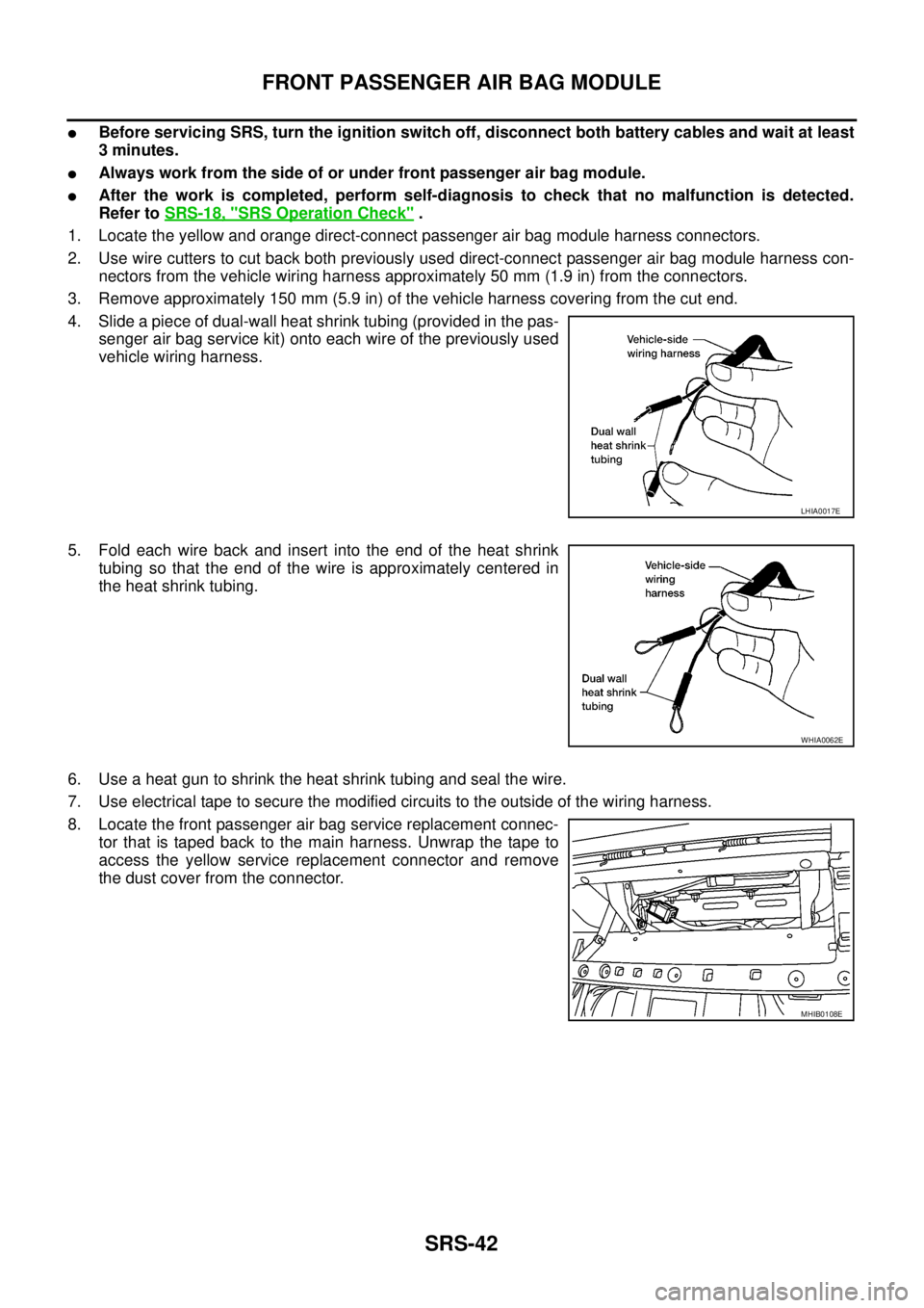
4. Slide a piece of dual-wall heat shrink tubing (provided in the pas-
senger air bag service kit) onto each wire of the previously used
vehicle wiring harness.
5. Fold each wire back and insert into the end of the heat shrink
tubing so that the end of the wire is approximately centered in
the heat shrink tubing.
6. Use a heat gun to shrink the heat shrink tubing and seal the wire.
7. Use electrical tape to secure the modified circuits to the outside of the wiring harness.
8. Locate the front passenger air bag service replacement connec-
tor that is taped back to the main harness. Unwrap the tape to
access the yellow service replacement connector and remove
the dust cover from the connector.
LHIA0017E
WHIA0062E
MHIB0108E
Page 2958 of 3171
DISPOSAL OF AIR BAG MODULE AND SEAT BELT PRE-TENSIONER
SRS-49
C
D
E
F
G
I
J
K
L
MA
B
SRS
DISPOSAL OF AIR BAG MODULE AND SEAT BELT PRE-TENSIONERPFP:00014
Caution for Air Bag Module and Seat Belt Pre-tensionerEHS001Y2
lBefore disposing of air bag module, seat belt pre-tensioner or vehicle equipped with such systems, deploy
the systems. If such systems have already been deployed due to an accident, dispose of them as indi-
cated in “SRS-49, "
DISPOSAL OF AIR BAG MODULE AND SEAT BELT PRE-TENSIONER".
lWhen deploying the air bag module or seat belt pre-tensioner, always use the Special Service Tool
Deployment tool [KV99106400].
lWhen deploying the air bag module or seat belt pre-tensioner, stand at least 5 m (16 ft) away from the
component being deployed.
lWhen deploying air bag module or seat belt pre-tensioner, a fairly loud noise is made, followed by smoke
being released. The smoke is not poisonous, however, be careful not to inhale smoke since it irritates the
throat and can cause choking.
lOnly deploy one air bag module or seat belt pre-tensioner at a time.
lDue to heat, leave deployed air bag module unattended for at least 30 minutes after deployment. Leave
deployed seat belt pre-tensioner unattended for at least 10 minutes after deployment.
lBe sure to wear gloves when handling a deployed air bag module or seat belt pre-tensioner.
lNever apply water to the deployed air bag module or seat belt pre-tensioner.
lWash your hands thoroughly after finishing work.
lPlace the vehicle outdoors with an open space of at least 6 m (20 ft) on all sides when deploying air bag
module or seat belt pre-tensioner while mounted in vehicle.
lUse a voltmeter to make sure the vehicle battery is fully charged.
lDo not dispose of the air bag module or seat belt pre-tensioner undeployed.
CHECKING DEPLOYMENT TOOL
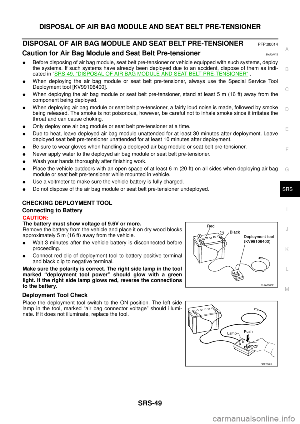
Connecting to Battery
CAUTION:
The battery must show voltage of 9.6V or more.
Remove the battery from the vehicle and place it on dry wood blocks
approximately 5 m (16 ft) away from the vehicle.
lWait 3 minutes after the vehicle battery is disconnected before
proceeding.
lConnect red clip of deployment tool to battery positive terminal
and black clip to negative terminal.
Makesurethepolarityiscorrect.Therightsidelampinthetool
marked “deployment tool power” should glow with a green
light. If the right side lamp glows red, reverse the connections
to the battery.
Deployment Tool Check
Place the deployment tool switch to the ON position. The left side
lamp in the tool, marked “air bag connector voltage” should illumi-
nate. If it does not illuminate, replace the tool.
PHIA0003E
SBF266H
Page 2968 of 3171
TF-1
TRANSFER
D DRIVELINE/AXLE
CONTENTS
C
E
F
G
H
I
J
K
L
M
SECTIONTF
A
B
TF
TRANSFER
PRECAUTIONS .......................................................... 4
Precautions for Supplemental Restraint System
(SRS)“AIRBAG”and“SEATBELTPRE-TEN-
SIONER” .................................................................. 4
Precautions for Transfer Assembly and Transfer
Control Unit Replacement ........................................ 4
CHECK 4WD SHIFT INDICATOR PATTERN ....... 4
METHOD FOR ADJUSTMENT WITH 4WD
SHIFT SWITCH AT “2WD” .................................... 5
METHOD FOR ADJUSTMENT WITH 4WD
SHIFT SWITCH AT “4H” OR “4LO” ....................... 5
Precautions .............................................................. 6
Service Notice .......................................................... 6
Wiring Diagrams and Trouble Diagnosis .................. 7
PREPARATION ........................................................... 8
Special Service Tools ............................................... 8
Commercial Service Tools ...................................... 10
NOISE, VIBRATION AND HARSHNESS (NVH)
TROUBLESHOOTING ...............................................11
NVH Troubleshooting Chart .................................... 11
TRANSFER FLUID ................................................... 12
Replacement .......................................................... 12
DRAINING ........................................................... 12
FILLING ............................................................... 12
Inspection ............................................................... 12
FLUID LEAKAGE AND FLUID LEVEL ................ 12
4WD SYSTEM .......................................................... 13
Cross-Section View ................................................ 13
Power Transfer ....................................................... 14
POWER TRANSFER DIAGRAM ........................ 14
POWER TRANSFER FLOW ............................... 15
System Description ................................................ 15
TRANSFER CONTROL DEVICE ........................ 15
WAIT DETECTION SWITCH .............................. 15
4LO SWITCH ...................................................... 15
ATP SWITCH ...................................................... 15
TRANSFER CONTROL UNIT ............................. 15
TRANSFER SHIFT RELAY ................................. 15
TRANSFER SHUT OFF RELAY ......................... 15
4WD SHIFT SWITCH AND INDICATOR LAMP... 164WD WARNING LAMP ....................................... 17
ATP WARNING LAMP (A/T MODELS) ................ 17
System Diagram ..................................................... 18
COMPONENTS FUNCTION ............................... 18
CAN Communication .............................................. 19
SYSTEM DESCRIPTION .................................... 19
TROUBLE DIAGNOSIS ............................................ 20
How to Perform Trouble Diagnosis ......................... 20
BASIC CONCEPT ............................................... 20
Location of Electrical Parts ..................................... 21
A/T MODELS ....................................................... 21
M/T MODELS ...................................................... 22
Circuit Diagram ....................................................... 23
A/T MODELS ....................................................... 23
M/T MODELS ...................................................... 24
Wiring Diagram — T/F — ....................................... 25
A/T MODELS ....................................................... 25
M/T MODELS ...................................................... 31
Trouble Diagnosis Chart for Symptoms .................. 38
Transfer Control Unit Input/Output Signal Refer-
ence Values ............................................................ 38
TRANSFER CONTROL UNIT INSPECTION
TABLE ................................................................. 38
CONSULT-II Function (ALL MODE AWD/4WD) ..... 44
FUNCTION .......................................................... 44
CONSULT-II SETTING PROCEDURE ................ 44
SELF-DIAG RESULT MODE ............................... 45
DATA MONITOR MODE ...................................... 47
Self-Diagnostic Procedure ...................................... 49
SELF-DIAGNOSTIC PROCEDURE (WITH
CONSULT-II) ....................................................... 49
SELF-DIAGNOSTIC PROCEDURE (WITHOUT
CONSULT-II) ....................................................... 49
ERASE SELF-DIAGNOSIS ................................. 51
TROUBLE DIAGNOSIS FOR SYSTEM .................... 52
Power Supply Circuit For Transfer Control Unit ...... 52
CONSULT-II REFERENCE VALUE IN DATA
MONITOR MODE ................................................ 52
TRANSFER CONTROL UNIT TERMINALS AND
REFERENCE VALUE .......................................... 52
Page 2970 of 3171

TF-3
C
E
F
G
H
I
J
K
L
MA
B
TF PLANETARY CARRIER ......................................... 129
Disassembly and Assembly ................................. 129
DISASSEMBLY ................................................. 129
INSPECTION AFTER DISASSEMBLY ............. 130
ASSEMBLY ....................................................... 131
FRONT DRIVE SHAFT ........................................... 133
Disassembly and Assembly ................................. 133
DISASSEMBLY ................................................. 133
INSPECTION AFTER DISASSEMBLY ............. 133
ASSEMBLY ....................................................... 134SHIFT CONTROL ...................................................135
Disassembly and Assembly ..................................135
DISASSEMBLY (A/T MODELS) ........................135
DISASSEMBLY (M/T MODELS) ........................135
INSPECTION AFTER DISASSEMBLY ..............136
ASSEMBLY (A/T MODELS) ..............................136
ASSEMBLY (M/T MODELS) ..............................137
SERVICE DATA AND SPECIFICATIONS (SDS) ....138
General Specifications ..........................................138
Inspection and Adjustment ...................................138
PINION GEAR END PLAY ................................138
CLEARANCE BETWEEN SHIFT FORK AND
SLEEVE ............................................................138
Page 2971 of 3171
TF-4
PRECAUTIONS
PRECAUTIONS
PFP:00001
Precautions for Supplemental Restraint System (SRS) “AIR BAG” and “SEAT
BELT PRE-TENSIONER”
EDS003ID
The Supplemental Restraint System such as “AIR BAG” and “SEAT BELT PRE-TENSIONER”, used along
with a front seat belt, helps to reduce the risk or severity of injury to the driver and front passenger for certain
types of collision. Information necessary to service the system safely is included in the SRS and SB section of
this Service Manual.
WARNING:
lTo avoid rendering the SRS inoperative, which could increase the risk of personal injury or death
in the event of a collision which would result in air bag inflation, all maintenance must be per-
formed by an authorized NISSAN/INFINITI dealer.
lImproper maintenance, including incorrect removal and installation of the SRS, can lead to per-
sonal injury caused by unintentional activation of the system. For removal of Spiral Cable and Air
Bag Module, see the SRS section.
lDo not use electrical test equipment on any circuit related to the SRS unless instructed to in this
Service Manual. SRS wiring harnesses can be identified by yellow and/or orange harnesses or
harness connectors.
Precautions for Transfer Assembly and Transfer Control Unit ReplacementEDS0031A
lWhen replacing transfer assembly or transfer control unit, check the 4WD shift indicator pattern and
adjustment of the position between transfer assembly and transfer control unit if necessary.
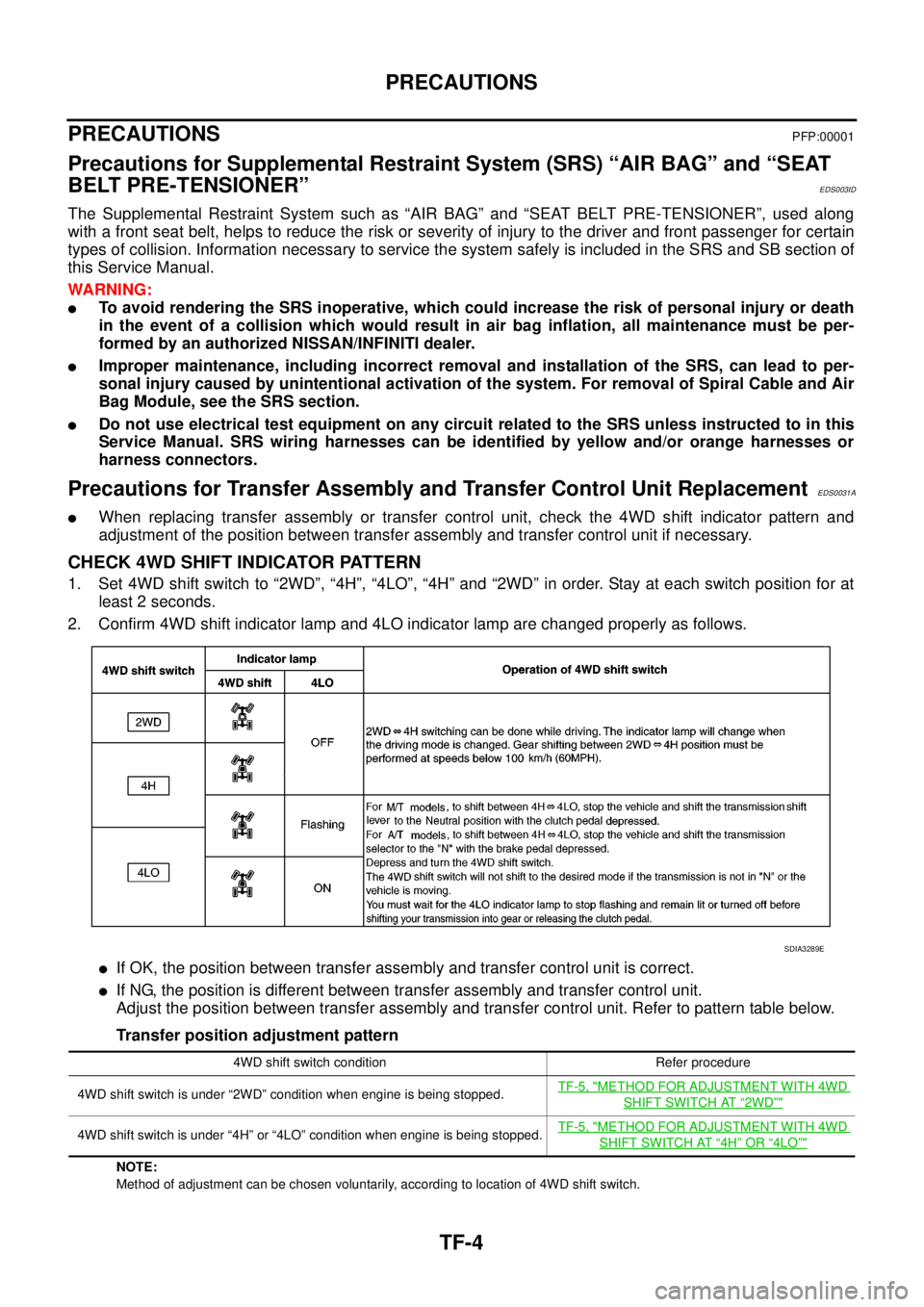
CHECK 4WD SHIFT INDICATOR PATTERN
1. Set 4WD shift switch to “2WD”, “4H”, “4LO”, “4H” and “2WD” in order. Stay at each switch position for at
least 2 seconds.
2. Confirm 4WD shift indicator lamp and 4LO indicator lamp are changed properly as follows.
lIf OK, the position between transfer assembly and transfer control unit is correct.
lIf NG, the position is different between transfer assembly and transfer control unit.
Adjust the position between transfer assembly and transfer control unit. Refer to pattern table below.
Transfer position adjustment pattern
NOTE:
Method of adjustment can be chosen voluntarily, according to location of 4WD shift switch.
SDIA3289E
4WD shift switch condition Refer procedure
4WD shift switch is under “2WD” condition when engine is being stopped.TF-5, "
METHOD FOR ADJUSTMENT WITH 4WD
SHIFT SWITCH AT“2WD”"
4WD shift switch is under “4H” or “4LO” condition when engine is being stopped.TF-5, "METHOD FOR ADJUSTMENT WITH 4WD
SHIFT SWITCH AT“4H”OR“4LO”"
Page 2973 of 3171
TF-6
PRECAUTIONS
If 4WD shift indicator lamp and 4LO indicator lamp do not indicate proper pattern, install new transfer con-
trol unit and retry the above check.
PrecautionsEDS0031B
lBefore connecting or disconnecting the transfer control unit harness connector, turn ignition
switch “OFF” and disconnect the battery cables. Battery voltage is applied to transfer control unit
even if ignition switch is turned “OFF”.
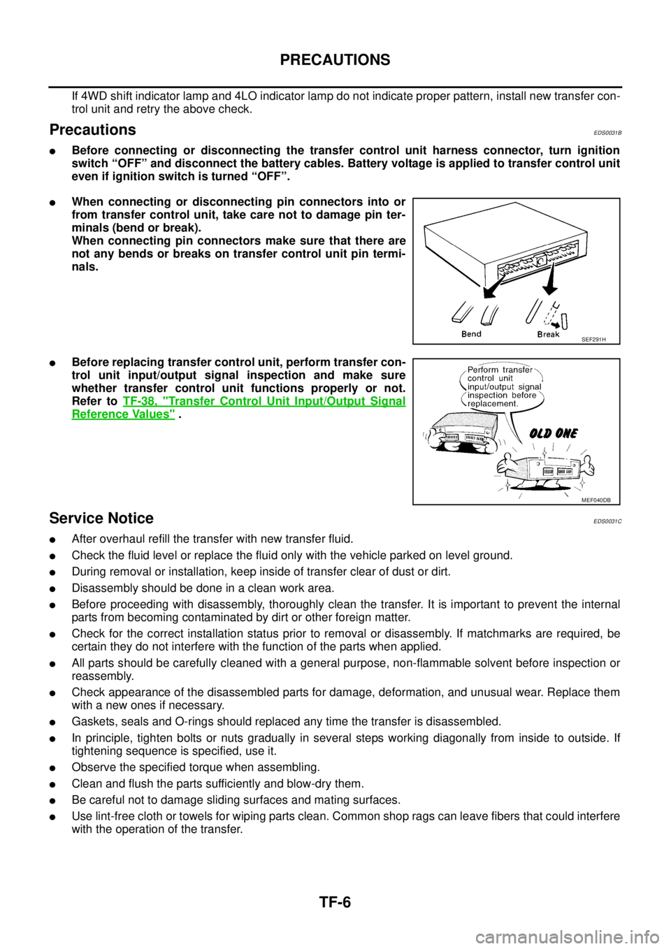
lWhen connecting or disconnecting pin connectors into or
from transfer control unit, take care not to damage pin ter-
minals (bend or break).
When connecting pin connectors make sure that there are
not any bends or breaks on transfer control unit pin termi-
nals.
lBefore replacing transfer control unit, perform transfer con-
trol unit input/output signal inspection and make sure
whether transfer control unit functions properly or not.
Refer toTF-38, "
Transfer Control Unit Input/Output Signal
Reference Values".
Service NoticeEDS0031C
lAfter overhaul refill the transfer with new transfer fluid.
lCheck the fluid level or replace the fluid only with the vehicle parked on level ground.
lDuring removal or installation, keep inside of transfer clear of dust or dirt.
lDisassemblyshouldbedoneinacleanworkarea.
lBefore proceeding with disassembly, thoroughly clean the transfer. It is important to prevent the internal
parts from becoming contaminated by dirt or other foreign matter.
lCheck for the correct installation status prior to removal or disassembly. If matchmarks are required, be
certain they do not interfere with the function of the parts when applied.
lAll parts should be carefully cleaned with a general purpose, non-flammable solvent before inspection or
reassembly.
lCheck appearance of the disassembled parts for damage, deformation, and unusual wear. Replace them
with a new ones if necessary.
lGaskets, seals and O-rings should replaced any time the transfer is disassembled.
lIn principle, tighten bolts or nuts gradually in several steps working diagonally from inside to outside. If
tightening sequence is specified, use it.
lObserve the specified torque when assembling.
lClean and flush the parts sufficiently and blow-dry them.
lBe careful not to damage sliding surfaces and mating surfaces.
lUse lint-free cloth or towels for wiping parts clean. Common shop rags can leave fibers that could interfere
with the operation of the transfer.
SEF291H
MEF040DB
Page 2975 of 3171
TF-8
PREPARATION
PREPARATION
PFP:00002
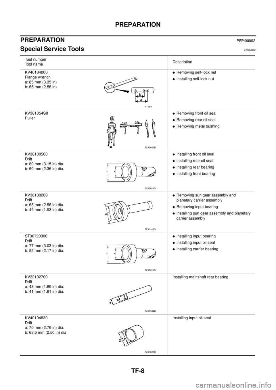
Special Service ToolsEDS0031E
Tool number
Tool nameDescription
KV40104000
Flange wrench
a: 85 mm (3.35 in)
b: 65 mm (2.56 in)
lRemoving self-lock nut
lInstalling self-lock nut
KV381054S0
Puller
lRemoving front oil seal
lRemoving rear oil seal
lRemoving metal bushing
KV38100500
Drift
a: 80 mm (3.15 in) dia.
b: 60 mm (2.36 in) dia.
lInstalling front oil seal
lInstalling rear oil seal
lInstalling rear bearing
lInstalling front bearing
KV38100200
Drift
a: 65 mm (2.56 in) dia.
b: 49 mm (1.93 in) dia.
lRemoving sun gear assembly and
planetary carrier assembly
lRemoving input bearing
lInstalling sun gear assembly and planetary
carrier assembly
ST30720000
Drift
a: 77 mm (3.03 in) dia.
b: 55 mm (2.17 in) dia.
lInstalling input bearing
lInstalling input oil seal
lInstalling carrier bearing
KV32102700
Drift
a: 48 mm (1.89 in) dia.
b: 41 mm (1.61 in) dia.Installing mainshaft rear bearing
KV40104830
Drift
a: 70 mm (2.76 in) dia.
b: 63.5 mm (2.50 in) dia.Installing input oil seal
NT659
ZZA0601D
ZZA0811D
ZZA1143D
ZZA0811D
ZZA0534D
ZZA1003D
Page 2977 of 3171
TF-10
PREPARATION
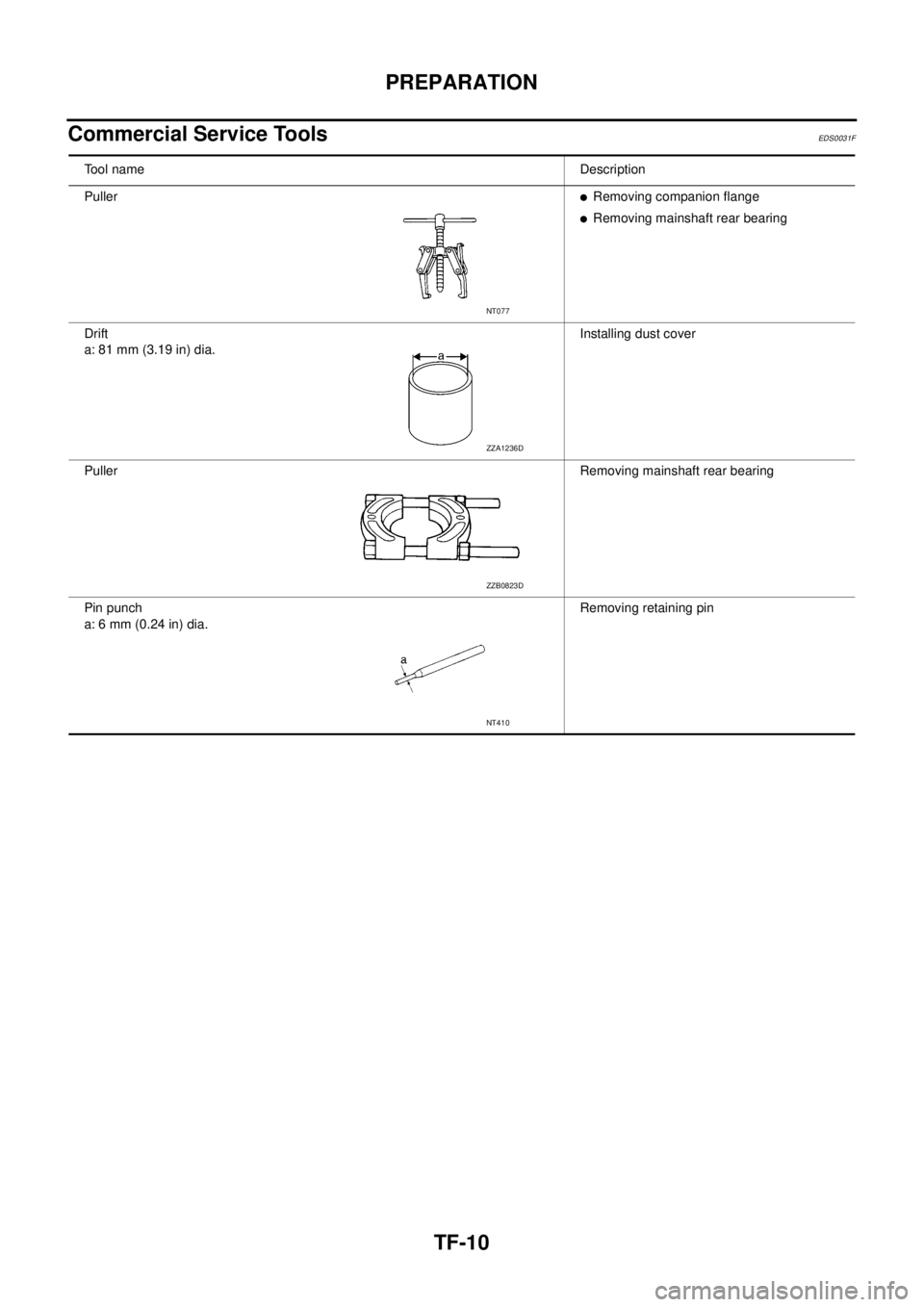
Commercial Service Tools
EDS0031F
Tool nameDescription
Puller
lRemoving companion flange
lRemoving mainshaft rear bearing
Drift
a: 81 mm (3.19 in) dia.Installing dust cover
PullerRemoving mainshaft rear bearing
Pin punch
a: 6 mm (0.24 in) dia.Removing retaining pin
NT077
ZZA1236D
ZZB0823D
NT410