2005 NISSAN NAVARA service
[x] Cancel search: servicePage 2876 of 3171
SQUEAK AND RATTLE TROUBLE DIAGNOSES
SE-5
C
D
E
F
G
H
J
K
L
MA
B
SE
DUPLICATE THE NOISE AND TEST DRIVE
If possible, drive the vehicle with the customer until the noise is duplicated. Note any additional information on
the Diagnostic Worksheet regarding the conditions or location of the noise. This information can be used to
duplicate the same conditions when you confirm the repair.
If the noise can be duplicated easily during the test drive, to help identify the source of the noise, try to dupli-
cate the noise with the vehicle stopped by doing one or all of the following:
1) Close a door.
2) Tap or push/pull around the area where the noise appears to be coming from.
3) Rev the engine.
4) Use a floor jack to recreate vehicle “twist”.
5) At idle, apply engine load (electrical load, half-clutch on M/T models, drive position on A/T models).
6) Raisethevehicleonahoistandhitatirewitharubberhammer.
lDrive the vehicle and attempt to duplicate the conditions the customer states exist when the noise occurs.
lIf it is difficult to duplicate the noise, drive the vehicle slowly on an undulating or rough road to stress the
vehicle body.
CHECK RELATED SERVICE BULLETINS
After verifying the customer concern or symptom, check ASIST for Technical Service Bulletins (TSBs) related
to that concern or symptom.
If a TSB relates to the symptom, follow the procedure to repair the noise.
LOCATE THE NOISE AND IDENTIFY THE ROOT CAUSE
1. Narrow down the noise to a general area. To help pinpoint the source of the noise, use a listening tool
(Engine Ear or mechanics stethoscope).
2. Narrow down the noise to a more specific area and identify the cause of the noise by:
lremoving the components in the area that you suspect the noise is coming from.
Do not use too much force when removing clips and fasteners, otherwise clips and fastener can be broken
or lost during the repair, resulting in the creation of new noise.
ltapping or pushing/pulling the component that you suspect is causing the noise.
Do not tap or push/pull the component with excessive force, otherwise the noise will be eliminated only
temporarily.
lfeeling for a vibration with your hand by touching the component(s) that you suspect is (are) causing the
noise.
lplacing a piece of paper between components that you suspect are causing the noise.
llooking for loose components and contact marks.
Refer toSE-6, "
Generic Squeak and Rattle Troubleshooting".
REPAIR THE CAUSE
lIf the cause is a loose component, tighten the component securely.
lIf the cause is insufficient clearance between components:
–separate components by repositioning or loosening and retightening the component, if possible.
–insulate components with a suitable insulator such as urethane pads, foam blocks, felt cloth tape or ure-
thane tape are available through your authorized Nissan Parts Department.
CAUTION:
Do not use excessive force as many components are constructed of plastic and may be damaged.
NOTE:
Always check with the Parts Department for the latest parts information.
Each item can be ordered separately as needed.
URETHANE PADS [1.5 mm (0.059 in) thick]
Insulates connectors, harness, etc.
76268-9E005: 100´135 mm (3.94´5.31 in)/76884-71L01: 60´85 mm (2.36´3.35 in)/76884-71L02: 15´
25 mm (0.59´0.98 in)
INSULATOR (Foam blocks)
Insulates components from contact. Can be used to fill space behind a panel.
73982-9E000: 45 mm (1.77 in) thick, 50´50 mm (1.97´1.97 in)/73982-50Y00: 10 mm (0.39 in) thick, 50
´50 mm (1.97´1.97 in)
INSULATOR (Light foam block)
80845-71L00: 30 mm (1.18 in) thick, 30´50 mm (1.18´1.97 in)
Page 2910 of 3171

SRS-1
SUPPLEMENTAL RESTRAINT SYSTEM (SRS)
H RESTRAINTS
CONTENTS
C
D
E
F
G
I
J
K
L
M
SECTIONSRS
A
B
SRS
SUPPLEMENTAL RESTRAINT SYSTEM (SRS)
PRECAUTIONS .......................................................... 3
Precautions for Supplemental Restraint System
(SRS)“AIRBAG”and“SEATBELTPRE-TEN-
SIONER” .................................................................. 3
Precautions for SRS “AIR BAG” and “SEAT BELT
PRE-TENSIONER” Service ..................................... 3
Precautions for Trouble Diagnosis ........................... 3
PREPARATION ........................................................... 4
Special Service Tools ............................................... 4
Commercial Service Tools ........................................ 5
SUPPLEMENTAL RESTRAINT SYSTEM (SRS) ....... 6
SRS Configuration ................................................... 6
Front Seat Belt Pre-Tensioner with Load Limiter ...... 7
Front Side Air Bag .................................................... 7
Side Curtain Air Bag ................................................. 7
Direct-Connect SRS Component Connectors .......... 8
TROUBLE DIAGNOSIS .............................................. 9
Trouble Diagnosis Introduction ................................. 9
DIAGNOSIS FUNCTION ....................................... 9
HOW TO PERFORM TROUBLE DIAGNOSES
FOR QUICK AND ACCURATE REPAIR ............... 9
WORK FLOW ...................................................... 10
SRS Components Parts Location ............................ 11
Schematic .............................................................. 12
Wiring Diagram–SRS– ........................................... 13
CONSULT-II Function (AIR BAG) ........................... 16
CONSULT-II Function ............................................ 16
HOW TO CHANGE SELF-DIAGNOSIS MODE
WITH CONSULT-II .............................................. 16
HOW TO ERASE SELF-DIAGNOSIS RESULTS... 17
Self-Diagnosis Function (Without CONSULT-II) ..... 17
HOW TO CHANGE SELF-DIAGNOSIS MODE... 17
HOW TO ERASE SELF-DIAGNOSIS RESULTS... 18
SRS Operation Check ............................................ 18
DIAGNOSTIC PROCEDURE 1 ........................... 18
Trouble Diagnosis With CONSULT-II ..................... 20
DIAGNOSTIC PROCEDURE 2 ........................... 20
DIAGNOSTIC PROCEDURE 3 ........................... 24
DIAGNOSTIC PROCEDURE 4 (CONTINUEDFROM DIAGNOSTIC PROCEDURE 2) .............. 26
DIAGNOSTIC PROCEDURE 5 ........................... 26
Trouble Diagnosis Without CONSULT-II ................. 30
DIAGNOSTIC PROCEDURE 6 ........................... 30
WARNING LAMP FLASH CODE CHART ........... 31
Trouble Diagnosis: “AIR BAG” Warning Lamp Does
Not Turn OFF ......................................................... 34
DIAGNOSTIC PROCEDURE 7 ........................... 34
Trouble Diagnosis: “AIR BAG” Warning Lamp Does
Not Turn ON ........................................................... 35
DIAGNOSTIC PROCEDURE 8 ........................... 35
DRIVER AIR BAG MODULE .................................... 36
Removal and Installation ........................................ 36
REMOVAL ........................................................... 36
INSTALLATION ................................................... 37
SPIRAL CABLE ........................................................ 38
Removal and Installation ........................................ 38
REMOVAL ........................................................... 38
INSTALLATION ................................................... 39
FRONT PASSENGER AIR BAG MODULE .............. 40
Removal and Installation ........................................ 40
REMOVAL ........................................................... 40
INSTALLATION ................................................... 41
WIRING HARNESS MODIFICATION .................. 41
FRONT SIDE AIR BAG MODULE ............................ 43
Removal and Installation ........................................ 43
REMOVAL ........................................................... 43
INSTALLATION ................................................... 43
SIDE CURTAIN AIR BAG MODULE ........................ 44
Removal and Installation ........................................ 44
REMOVAL ........................................................... 44
INSTALLATION ................................................... 44
SIDE AIR BAG (SATELLITE) SENSOR ................... 46
Removal and Installation ........................................ 46
REMOVAL ........................................................... 46
INSTALLATION ................................................... 46
FRONT SEAT BELT PRE-TENSIONER ................... 47
Removal and Installation ........................................ 47
Page 2912 of 3171
PRECAUTIONS
SRS-3
C
D
E
F
G
I
J
K
L
MA
B
SRS
PRECAUTIONSPFP:00001
Precautions for Supplemental Restraint System (SRS) “AIR BAG” and “SEAT
BELT PRE-TENSIONER”
EHS001Y8
The Supplemental Restraint System such as “AIR BAG” and “SEAT BELT PRE-TENSIONER”, used along
with a front seat belt, helps to reduce the risk or severity of injury to the driver and front passenger for certain
types of collision. Information necessary to service the system safely is included in the SRS and SB section of
this Service Manual.
WARNING:
lTo avoid rendering the SRS inoperative, which could increase the risk of personal injury or death
in the event of a collision which would result in air bag inflation, all maintenance must be per-
formed by an authorized NISSAN/INFINITI dealer.
lImproper maintenance, including incorrect removal and installation of the SRS, can lead to per-
sonal injury caused by unintentional activation of the system. For removal of Spiral Cable and Air
Bag Module, see the SRS section.
lDo not use electrical test equipment on any circuit related to the SRS unless instructed to in this
Service Manual. SRS wiring harnesses can be identified by yellow and/or orange harnesses or
harness connectors.
Precautions for SRS “AIR BAG” and “SEAT BELT PRE-TENSIONER” ServiceEHS001Y9
lDo not use electrical test equipment to check SRS circuits unless instructed to in this Service Manual.
lBefore servicing the SRS, turn ignition switch OFF, disconnect both battery cables and wait at least 3 min-
utes.
For approximately 3 minutes after the cables are removed, it is still possible for the air bag and seat belt
pre-tensioner to deploy. Therefore, do not work on any SRS connectors or wires until at least 3 minutes
have passed.
lDiagnosis sensor unit must always be installed with their arrow marks “Ü” pointing towards the front of the
vehicle for proper operation. Also check diagnosis sensor unit for cracks, deformities or rust before instal-
lation and replace as required.
lThe spiral cable must be aligned with the neutral position since its rotations are limited. Do not attempt to
turn steering wheel or column after removal of steering gear.
lHandle air bag module carefully. Always place driver and front passenger air bag modules with the pad
side facing upward and place front side air bag module standing with stud bolt side setting bottom.
lConduct self-diagnosis to check entire SRS for proper function after replacing any components.
lAfter air bag inflates, the front instrument panel assembly should be replaced if damaged.
lAlways replace instrument panel pad following front passenger air bag deployment.
Precautions for Trouble DiagnosisEHS001YA
When you read wiring diagrams, refer to the following:
lGI-15, "How to Read Wiring Diagrams"in GI section
lPG-4, "POWER SUPPLY ROUTING CIRCUIT"in PG section
When you perform trouble diagnosis, refer to the following:
lGI-11, "How to Follow Trouble Diagnoses"in GI section
lGI-24, "How to Perform Efficient Diagnosis for an Electrical Incident"in GI section
Check for any service bulletins before servicing the vehicle.
Page 2913 of 3171
SRS-4
PREPARATION
PREPARATION
PFP:00002
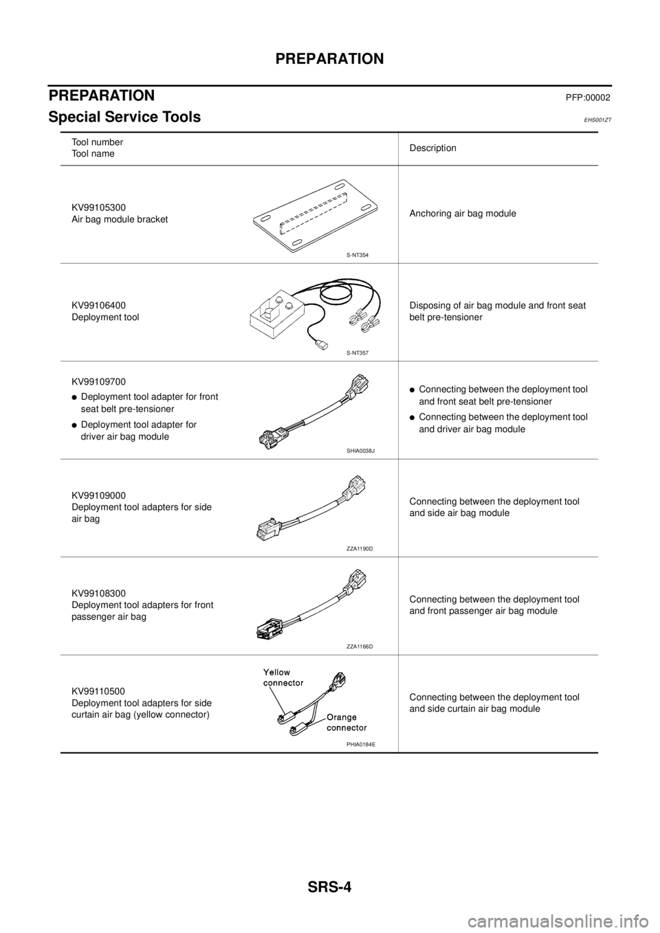
Special Service ToolsEHS001ZT
Tool number
Tool nameDescription
KV99105300
Air bag module bracketAnchoring air bag module
KV99106400
Deployment toolDisposing of air bag module and front seat
belt pre-tensioner
KV99109700
lDeployment tool adapter for front
seat belt pre-tensioner
lDeployment tool adapter for
driver air bag module
lConnecting between the deployment tool
and front seat belt pre-tensioner
lConnecting between the deployment tool
and driver air bag module
KV99109000
Deployment tool adapters for side
air bagConnecting between the deployment tool
and side air bag module
KV99108300
Deployment tool adapters for front
passenger air bagConnecting between the deployment tool
and front passenger air bag module
KV99110500
Deployment tool adapters for side
curtain air bag (yellow connector)Connecting between the deployment tool
and side curtain air bag module
S-NT354
S-NT357
SHIA0038J
ZZA1190D
ZZA1166D
PHIA0184E
Page 2914 of 3171
PREPARATION
SRS-5
C
D
E
F
G
I
J
K
L
MA
B
SRS
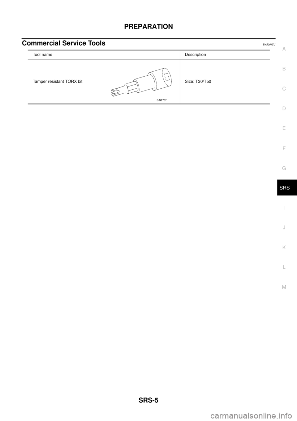
Commercial Service ToolsEHS001ZU
Tool name Description
Tamper resistant TORX bit Size: T30/T50
S-NT757
Page 2918 of 3171
TROUBLE DIAGNOSIS
SRS-9
C
D
E
F
G
I
J
K
L
MA
B
SRS
TROUBLE DIAGNOSISPFP:00004
Trouble Diagnosis IntroductionEHS001XG
CAUTION:
lDo not use electrical test equipment on any circuit related to the SRS unless instructed to do so in
this Service Manual. SRS wiring harnesses can be identified by yellow and/or orange harness con-
nectors.
lDo not attempt to repair, splice or modify SRS wiring harnesses. If a harness is damaged, replace
it with a new one.
lKeep ground connections clean.
DIAGNOSIS FUNCTION
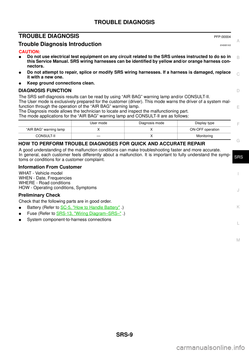
The SRS self-diagnosis results can be read by using “AIR BAG” warning lamp and/or CONSULT-II.
The User mode is exclusively prepared for the customer (driver). This mode warns the driver of a system mal-
function through the operation of the “AIR BAG” warning lamp.
The Diagnosis mode allows the technician to locate and inspect the malfunctioning part.
The mode applications for the “AIR BAG” warning lamp and CONSULT-II are as follows:
HOW TO PERFORM TROUBLE DIAGNOSES FOR QUICK AND ACCURATE REPAIR
A good understanding of the malfunction conditions can make troubleshooting faster and more accurate.
In general, each customer feels differently about a malfunction. It is important to fully understand the symp-
toms or conditions for a customer complaint.
Information From Customer
WHAT - Vehicle model
WHEN - Date, Frequencies
WHERE - Road conditions
HOW - Operating conditions, Symptoms
Preliminary Check
Check that the following parts are in good order.
lBattery (Refer toSC-5, "How to Handle Battery".)
lFuse (Refer toSRS-13, "Wiring Diagram–SRS–".)
lSystem component-to-harness connections
User mode Diagnosis mode Display type
“AIR BAG” warning lamp X X ON-OFF operation
CONSULT-II — X Monitoring
Page 2949 of 3171
SRS-40
FRONT PASSENGER AIR BAG MODULE
FRONT PASSENGER AIR BAG MODULE
PFP:K8515
Removal and InstallationEHS001XU
The passenger air bag module originally installed in the vehicle uses direct-connect style harness connectors.
Service replacement passenger air bag modules use tab-locking style harness connectors. If the passenger
air bag module is replaced or if the direct-connect harness connectors are damaged, the vehicle wiring har-
ness must be modified to allow connection of the service replacement passenger air bag module. Refer to
SRS-41, "
WIRING HARNESS MODIFICATION"for wiring harness modification procedure.
REMOVAL
CAUTION:
lDo not attempt to repair or replace damaged direct-connect front passenger air bag module con-
nectors. If a direct-connect harness connector is damaged, the front passenger air bag must be
replaced and the wiring harness modified.
lBefore servicing SRS, turn the ignition switch off, disconnect both battery cables and wait at least
3 minutes.
lAlways work from the side of or under front passenger air bag module.
1. Remove the glove box, then remove instrument panel. Refer toIP-10, "
INSTRUMENT PANEL ASSEM-
BLY".
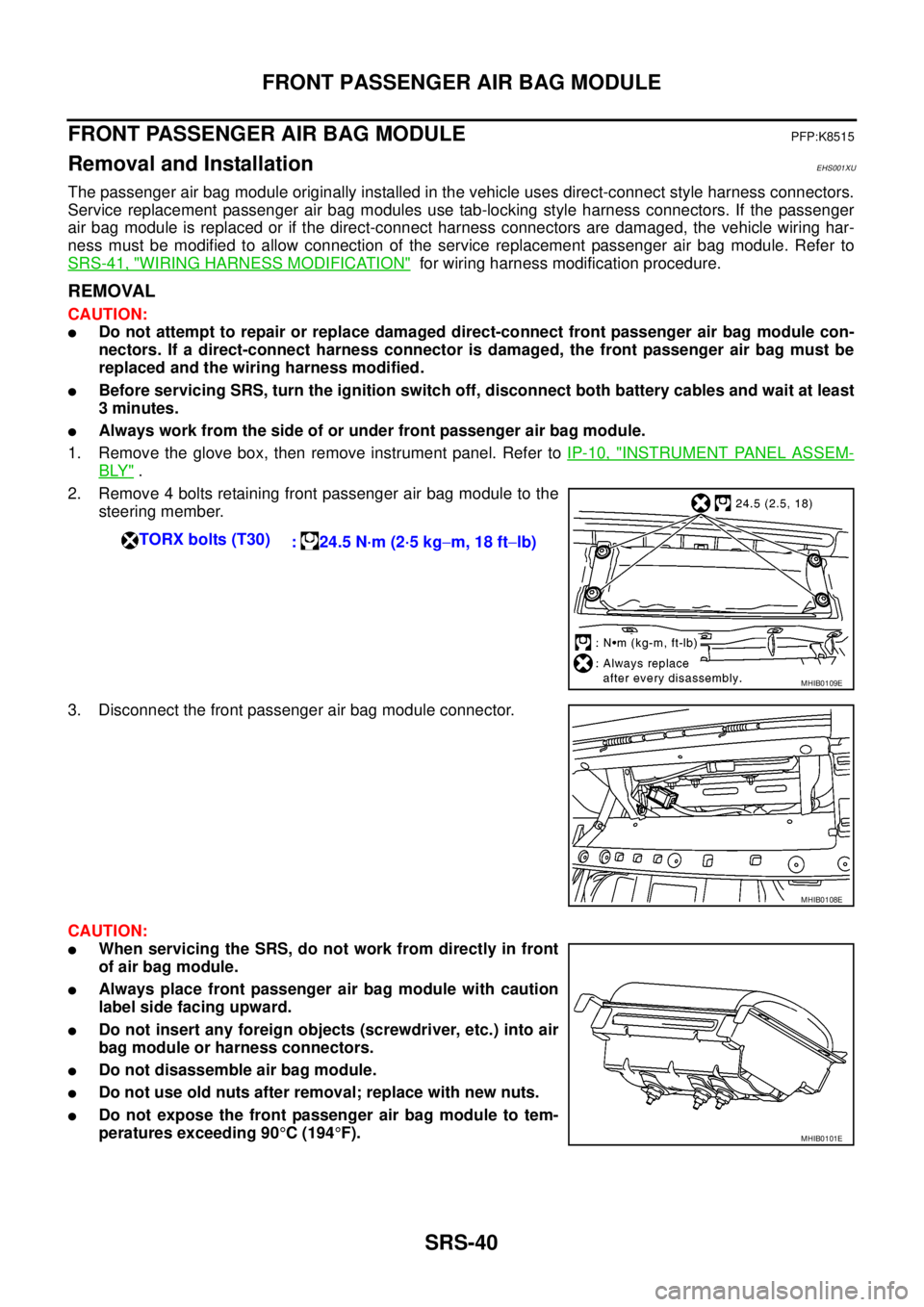
2. Remove 4 bolts retaining front passenger air bag module to the
steering member.
3. Disconnect the front passenger air bag module connector.
CAUTION:
lWhen servicing the SRS, do not work from directly in front
of air bag module.
lAlways place front passenger air bag module with caution
label side facing upward.
lDo not insert any foreign objects (screwdriver, etc.) into air
bag module or harness connectors.
lDo not disassemble air bag module.
lDo not use old nuts after removal; replace with new nuts.
lDo not expose the front passenger air bag module to tem-
peratures exceeding 90°C(194°F). TORX bolts (T30)
: 24.5 N·m (2·5 kg-m, 18 ft-lb)
MHIB0109E
MHIB0108E
MHIB0101E
Page 2950 of 3171
FRONT PASSENGER AIR BAG MODULE
SRS-41
C
D
E
F
G
I
J
K
L
MA
B
SRS
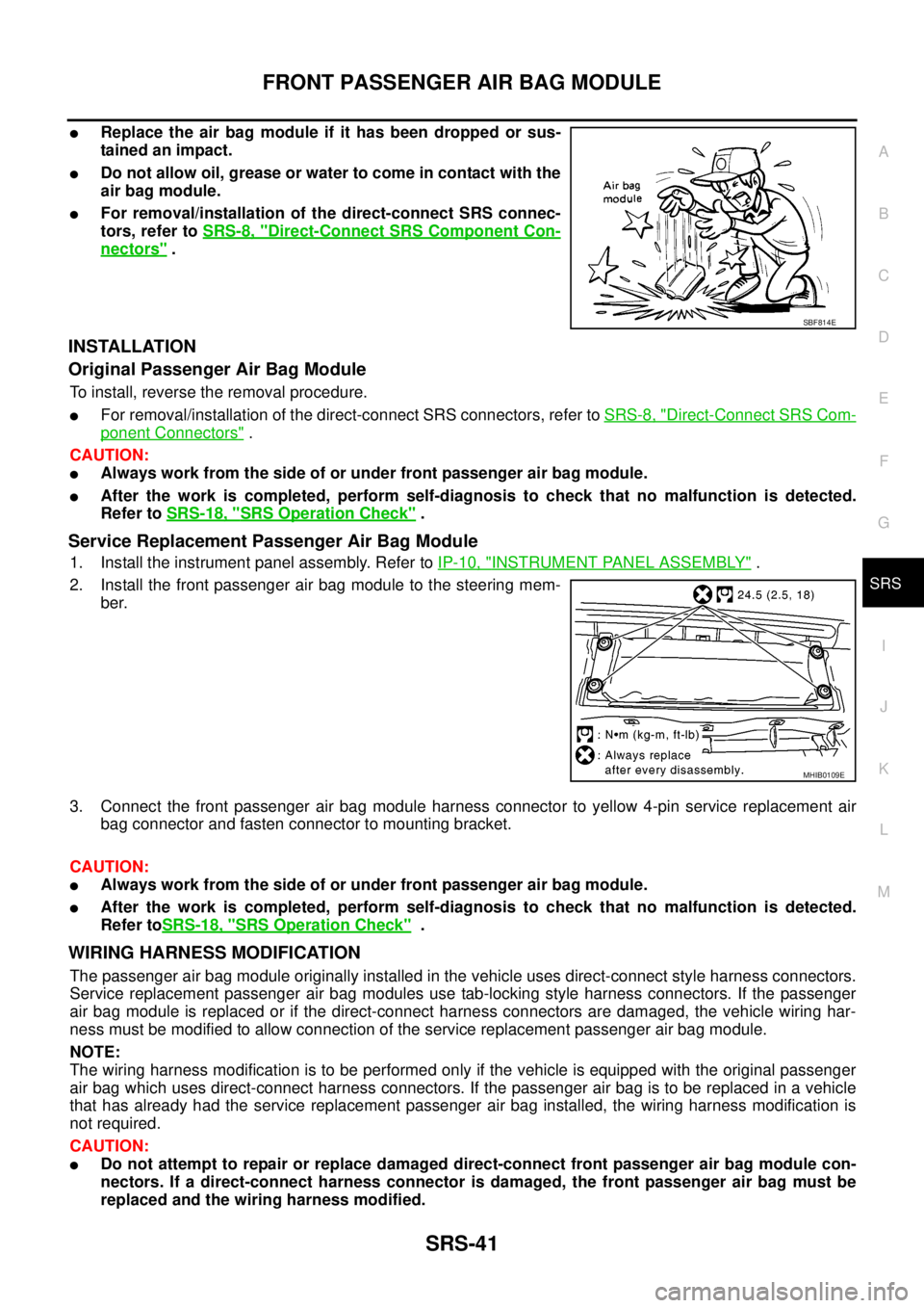
lReplace the air bag module if it has been dropped or sus-
tainedanimpact.
lDo not allow oil, grease or water to come in contact with the
air bag module.
lFor removal/installation of the direct-connect SRS connec-
tors, refer toSRS-8, "
Direct-Connect SRS Component Con-
nectors".
INSTALLATION
Original Passenger Air Bag Module
To install, reverse the removal procedure.
lFor removal/installation of the direct-connect SRS connectors, refer toSRS-8, "Direct-Connect SRS Com-
ponent Connectors".
CAUTION:
lAlways work from the side of or under front passenger air bag module.
lAfter the work is completed, perform self-diagnosis to check that no malfunction is detected.
Refer toSRS-18, "
SRS Operation Check".
Service Replacement Passenger Air Bag Module
1. Install the instrument panel assembly. Refer toIP-10, "INSTRUMENT PANEL ASSEMBLY".
2. Install the front passenger air bag module to the steering mem-
ber.
3. Connect the front passenger air bag module harness connector to yellow 4-pin service replacement air
bag connector and fasten connector to mounting bracket.
CAUTION:
lAlways work from the side of or under front passenger air bag module.
lAfter the work is completed, perform self-diagnosis to check that no malfunction is detected.
Refer toSRS-18, "
SRS Operation Check".
WIRING HARNESS MODIFICATION
The passenger air bag module originally installed in the vehicle uses direct-connect style harness connectors.
Service replacement passenger air bag modules use tab-locking style harness connectors. If the passenger
air bag module is replaced or if the direct-connect harness connectors are damaged, the vehicle wiring har-
ness must be modified to allow connection of the service replacement passenger air bag module.
NOTE:
The wiring harness modification is to be performed only if the vehicle is equipped with the original passenger
air bag which uses direct-connect harness connectors. If the passenger air bag is to be replaced in a vehicle
that has already had the service replacement passenger air bag installed, the wiring harness modification is
not required.
CAUTION:
lDo not attempt to repair or replace damaged direct-connect front passenger air bag module con-
nectors. If a direct-connect harness connector is damaged, the front passenger air bag must be
replaced and the wiring harness modified.
SBF814E
MHIB0109E