2005 NISSAN NAVARA service
[x] Cancel search: servicePage 2810 of 3171
REAR SUSPENSION ASSEMBLY
RSU-5
C
D
F
G
H
I
J
K
L
MA
B
RSU
CAUTION:
When installing the components with rubber bushings, the final tightening of the nuts and bolts must
be done with the vehicle in an unladen condition (the fuel, engine coolant, and engine oil full; the
spare tire, jack, hand tools and mats in their designated positions) with the tires on the ground.
On-Vehicle Inspection and ServiceEES002JH
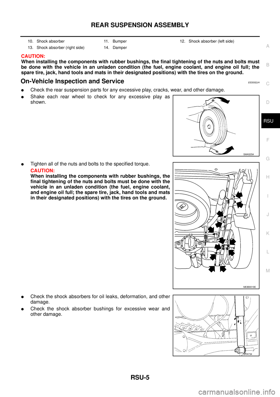
lCheck the rear suspension parts for any excessive play, cracks, wear, and other damage.
lShake each rear wheel to check for any excessive play as
shown.
lTighten all of the nuts and bolts to the specified torque.
CAUTION:
When installing the components with rubber bushings, the
final tightening of the nuts and bolts must be done with the
vehicle in an unladen condition (the fuel, engine coolant,
and engine oil full; the spare tire, jack, hand tools and mats
in their designated positions) with the tires on the ground.
lCheck the shock absorbers for oil leaks, deformation, and other
damage.
lCheck the shock absorber bushings for excessive wear and
other damage.
10. Shock absorber 11. Bumper 12. Shock absorber (left side)
13. Shock absorber (right side) 14. Damper
SMA525A
MEIB9019E
SRA734
Page 2816 of 3171
SERVICE DATA AND SPECIFICATIONS (SDS)
RSU-11
C
D
F
G
H
I
J
K
L
MA
B
RSU
SERVICE DATA AND SPECIFICATIONS (SDS)PFP:00030
General Specifications (Rear)EES002JK
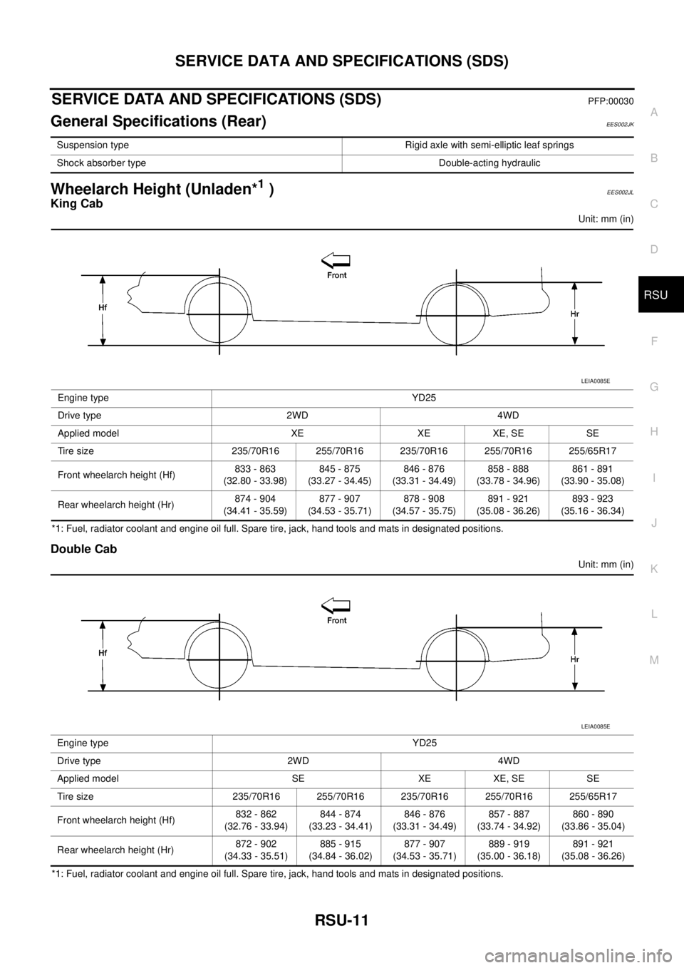
Wheelarch Height (Unladen*1)EES002JL
King Cab
Unit: mm (in)
*1: Fuel, radiator coolant and engine oil full. Spare tire, jack, hand tools and mats in designated positions.
Double Cab
Unit: mm (in)
*1: Fuel, radiator coolant and engine oil full. Spare tire, jack, hand tools and mats in designated positions.Suspension type Rigid axle with semi-elliptic leaf springs
Shock absorber type Double-acting hydraulic
Engine type YD25
Drive type 2WD 4WD
Applied model XE XE XE, SE SE
Tire size 235/70R16 255/70R16 235/70R16 255/70R16 255/65R17
Front wheelarch height (Hf)833 - 863
(32.80 - 33.98)845 - 875
(33.27 - 34.45)846 - 876
(33.31 - 34.49)858 - 888
(33.78 - 34.96)861 - 891
(33.90 - 35.08)
Rear wheelarch height (Hr)874 - 904
(34.41 - 35.59)877 - 907
(34.53 - 35.71)878 - 908
(34.57 - 35.75)891 - 921
(35.08 - 36.26)893 - 923
(35.16 - 36.34)
LEIA0085E
Engine type YD25
Drive type 2WD 4WD
Applied model SE XE XE, SE SE
Tire size 235/70R16 255/70R16 235/70R16 255/70R16 255/65R17
Front wheelarch height (Hf)832 - 862
(32.76 - 33.94)844 - 874
(33.23 - 34.41)846 - 876
(33.31 - 34.49)857 - 887
(33.74 - 34.92)860 - 890
(33.86 - 35.04)
Rear wheelarch height (Hr)872 - 902
(34.33 - 35.51)885 - 915
(34.84 - 36.02)877 - 907
(34.53 - 35.71)889 - 919
(35.00 - 36.18)891 - 921
(35.08 - 36.26)
LEIA0085E
Page 2817 of 3171

RSU-12
SERVICE DATA AND SPECIFICATIONS (SDS)
Page 2818 of 3171
SB-1
SEAT BELTS
H RESTRAINTS
CONTENTS
C
D
E
F
G
I
J
K
L
M
SECTIONSB
A
B
SB
SEAT BELTS
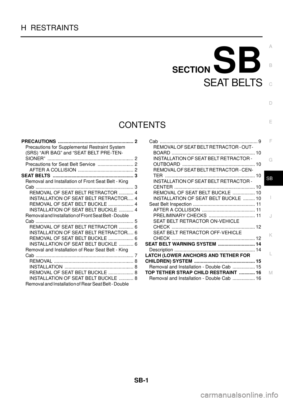
PRECAUTIONS .......................................................... 2
Precautions for Supplemental Restraint System
(SRS)“AIRBAG”and“SEATBELTPRE-TEN-
SIONER” .................................................................. 2
Precautions for Seat Belt Service ............................ 2
AFTER A COLLISION ........................................... 2
SEAT BELTS .............................................................. 3
Removal and Installation of Front Seat Belt - King
Cab ........................................................................... 3
REMOVAL OF SEAT BELT RETRACTOR ............ 4
INSTALLATION OF SEAT BELT RETRACTOR..... 4
REMOVAL OF SEAT BELT BUCKLE .................... 4
INSTALLATION OF SEAT BELT BUCKLE ............ 4
Removal and Installation of Front Seat Belt - Double
Cab ........................................................................... 5
REMOVAL OF SEAT BELT RETRACTOR ............ 6
INSTALLATION OF SEAT BELT RETRACTOR..... 6
REMOVAL OF SEAT BELT BUCKLE .................... 6
INSTALLATION OF SEAT BELT BUCKLE ............ 6
Removal and Installation of Rear Seat Belt - King
Cab ........................................................................... 7
REMOVAL ............................................................. 8
INSTALLATION ..................................................... 8
REMOVAL OF SEAT BELT BUCKLE .................... 8
INSTALLATION OF SEAT BELT BUCKLE ............ 8
Removal and Installation of Rear Seat Belt - DoubleCab ........................................................................... 9
REMOVAL OF SEAT BELT RETRACTOR - OUT-
BOARD ................................................................ 10
INSTALLATION OF SEAT BELT RETRACTOR -
OUTBOARD ........................................................ 10
REMOVALOFSEATBELTRETRACTOR-CEN-
TER ..................................................................... 10
INSTALLATION OF SEAT BELT RETRACTOR -
CENTER .............................................................. 10
REMOVAL OF SEAT BELT BUCKLE .................. 10
INSTALLATION OF SEAT BELT BUCKLE .......... 10
Seat Belt Inspection ................................................ 11
AFTER A COLLISION ......................................... 11
PRELIMINARY CHECKS .................................... 11
SEAT BELT RETRACTOR ON-VEHICLE
CHECK ................................................................ 12
SEAT BELT RETRACTOR OFF-VEHICLE
CHECK ................................................................ 12
SEAT BELT WARNING SYSTEM ............................. 14
Description .............................................................. 14
LATCH (LOWER ANCHORS AND TETHER FOR
CHILDREN) SYSTEM ............................................... 15
Removal and Installation - Double Cab .................. 15
TOP TETHER STRAP CHILD RESTRAINT ............. 16
Removal and Installation - Double Cab .................. 16
Page 2819 of 3171
SB-2
PRECAUTIONS
PRECAUTIONS
PFP:00001
Precautions for Supplemental Restraint System (SRS) “AIR BAG” and “SEAT
BELT PRE-TENSIONER”
EHS0026D
The Supplemental Restraint System such as “AIR BAG” and “SEAT BELT PRE-TENSIONER”, used along
with a front seat belt, helps to reduce the risk or severity of injury to the driver and front passenger for certain
types of collision. Information necessary to service the system safely is included in the SRS and SB section of
this Service Manual.
WARNING:
lTo avoid rendering the SRS inoperative, which could increase the risk of personal injury or death
in the event of a collision which would result in air bag inflation, all maintenance must be per-
formed by an authorized NISSAN/INFINITI dealer.
lImproper maintenance, including incorrect removal and installation of the SRS, can lead to per-
sonal injury caused by unintentional activation of the system. For removal of Spiral Cable and Air
Bag Module, see the SRS section.
lDo not use electrical test equipment on any circuit related to the SRS unless instructed to in this
Service Manual. SRS wiring harnesses can be identified by yellow and/or orange harnesses or
harness connectors.
Precautions for Seat Belt ServiceEHS00265
CAUTION:
lBefore removing the seat belt pre-tensioner assembly, turn the ignition switch OFF, disconnect
both battery cables and wait at least 3 minutes.
lDo not use electrical test equipment for seat belt pre-tensioner connector.
lAfter replacing or reinstalling seat belt pre-tensioner assembly, or reconnecting seat belt pre-
tensioner assembly connector, ensure entire SRS operates properly. Refer toSRS-18, "
SRS Oper-
ation Check".
lDeploy seat belt pre-tensioner assembly before disposing. Refer toSRS-49, "DISPOSAL OF AIR
BAG MODULE AND SEAT BELT PRE-TENSIONER".
lDo not disassemble buckle or seat belt assembly.
lReplace anchor bolts if they are deformed or worn out.
lNever oil tongue and buckle.
lIf any component of seat belt assembly is questionable, do not repair. Replace the whole seat belt
assembly.
lIf webbing is cut, frayed, or damaged, replace seat belt assembly.
lWhen replacing seat belt assembly, use a genuine NISSAN seat belt assembly.
AFTER A COLLISION
WARNING:
lInspect all seat belt assemblies including retractors and attaching hardware after any collision.
lNISSAN recommends that all seat belt assemblies in use during a collision be replaced unless the
collision was minor and the belts show no damage and continue to operate properly. Failure to do
so could result in serious personal injury in an accident. Seat belt assemblies not in use during a
collision should also be replaced if either damage or improper operation is noted. Seat belt pre-
tensioner should be replaced even if the seat belts are not in use during a frontal collision in which
the air bags are deployed.
Replace any seat belt assembly (including anchor bolts) if:
lThe seat belt was in use at the time of a collision (except for minor collisions and the belts, retractors and
buckles show no damage and continue to operate properly).
lThe seat belt was damaged in an accident. (i.e., torn webbing, bent retractor or guide, etc.)
lThe seat belt attaching point was damaged in an accident. Inspect the seat belt attaching area for damage
or distortion and repair as necessary before installing a new seat belt assembly.
lAnchor bolts are deformed or worn out.
lThe seat belt pre-tensioner should be replaced even if the seat belts are not in use during the collision in
which the air bags are deployed.
Page 2832 of 3171
LATCH (LOWER ANCHORS AND TETHER FOR CHILDREN) SYSTEM
SB-15
C
D
E
F
G
I
J
K
L
MA
B
SB
LATCH (LOWER ANCHORS AND TETHER FOR CHILDREN) SYSTEMPFP:75466
Removal and Installation - Double CabEHS0026B
NOTE:
The LATCH (Lower Anchors and Tether for Children) system is not serviceable.
Page 2833 of 3171

SB-16
TOP TETHER STRAP CHILD RESTRAINT
TOP TETHER STRAP CHILD RESTRAINT
PFP:88000
Removal and Installation - Double CabEHS0026C
NOTE:
The Top Tether Strap Child Restraint system is not serviceable.
Page 2834 of 3171
SC-1
STARTING & CHARGING SYSTEM
K ELECTRICAL
CONTENTS
C
D
E
F
G
H
I
J
L
M
SECTIONSC
A
B
SC
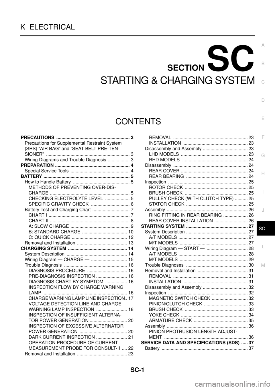
STARTING & CHARGING SYSTEM
PRECAUTIONS .......................................................... 3
Precautions for Supplemental Restraint System
(SRS)“AIRBAG”and“SEATBELTPRE-TEN-
SIONER” .................................................................. 3
Wiring Diagrams and Trouble Diagnosis .................. 3
PREPARATION ........................................................... 4
Special Service Tools ............................................... 4
BATTERY .................................................................... 5
How to Handle Battery ............................................. 5
METHODS OF PREVENTING OVER-DIS-
CHARGE ............................................................... 5
CHECKING ELECTROLYTE LEVEL .................... 5
SPECIFIC GRAVITY CHECK ............................... 6
Battery Test and Charging Chart .............................. 7
CHART I ................................................................ 7
CHART II ............................................................... 8
A: SLOW CHARGE ............................................... 9
B: STANDARD CHARGE .................................... 10
C: QUICK CHARGE ............................................ 12
Removal and Installation ........................................ 13
CHARGING SYSTEM ............................................... 14
System Description ................................................ 14
Wiring Diagram — CHARGE — ............................. 15
Trouble Diagnosis .................................................. 16
DIAGNOSIS PROCEDURE ................................ 16
PRE-DIAGNOSIS INSPECTION ......................... 16
DIAGNOSIS CHART BY SYMPTOM .................. 16
INSPECTION FLOW BY CHARGE WARNING
LAMP .................................................................. 16
CHARGE WARNING LAMP LINE INSPECTION... 17
VOLTAGE DETECTION LINE AND CHARGE
WARNING LAMP INSPECTION ......................... 18
INSPECTION OF INSUFFICIENT ALTERNA-
TOR POWER GENERATION .............................. 20
INSPECTION OF EXCESSIVE ALTERNATOR
POWER GENERATION ...................................... 20
DARK CURRENT INSPECTION ......................... 21
OPERATION PROCEDURE OF CURRENT
MEASUREMENT PROBE FOR CONSULT-II ..... 22
Removal and Installation ........................................ 23REMOVAL ........................................................... 23
INSTALLATION ................................................... 23
Disassembly and Assembly .................................... 23
LHD MODELS ..................................................... 23
RHD MODELS .................................................... 24
Disassembly ........................................................... 24
REAR COVER ..................................................... 24
REAR BEARING ................................................. 24
Inspection ............................................................... 25
ROTOR CHECK .................................................. 25
BRUSH CHECK .................................................. 25
PULLEY CHECK (WITH CLUTCH TYPE) ........... 25
STATOR CHECK ................................................. 25
Assembly ................................................................ 26
RING FITTING IN REAR BEARING .................... 26
REAR COVER INSTALLATION ........................... 26
STARTING SYSTEM ................................................. 27
System Description ................................................. 27
A/T MODELS ....................................................... 27
M/T MODELS ...................................................... 27
Wiring Diagram — START — ................................. 28
A/T MODELS ....................................................... 28
M/T MODELS ...................................................... 29
Trouble Diagnoses ................................................. 30
Removal and Installation ........................................ 31
REMOVAL ........................................................... 31
INSTALLATION ................................................... 31
Disassembly and Assembly .................................... 32
Inspection ............................................................... 32
MAGNETIC SWITCH CHECK ............................. 32
PINION/CLUTCH CHECK ................................... 33
BRUSH CHECK .................................................. 33
YOKE CHECK ..................................................... 34
ARMATURE CHECK ........................................... 35
Assembly ................................................................ 36
PINION PROTRUSION LENGTH ADJUST-
MENT .................................................................. 36
SERVICE DATA AND SPECIFICATIONS (SDS) ...... 37
Battery .................................................................... 37