Page 2631 of 3171
PS-4
PREPARATION
Commercial Service Tools
EGS001LB
Tool name Description
Power tool
lRemoving wheel nuts
lRemoving undercover
PBIC0190E
Page 2635 of 3171

PS-8
STEERING WHEEL
STEERING WHEEL
PFP:48430
On-Vehicle Inspection and ServiceEGS001LG
CHECKING CONDITION OF INSTALLATION
lCheck installation conditions of steering gear assembly, front suspension assembly, axle and steering col-
umn assembly.
lCheck if movement exists when steering wheel is moved up and down, to the left and right and to the axial
direction.
lCheck steering gear assembly mounting bolts and nuts for looseness. Refer toPS-14, "COMPONENT".
CHECKING STEERING WHEEL PLAY
lTurn steering wheel so that front wheels come to the straight-ahead position. Start engine and lightly turn
steering wheel to the left and right until front wheels start to move. Measure steering wheel movement on
the outer circumference.
lWhen the measurement value is outside the standard value, check backlash for each joint of steering col-
umn assembly and installation condition of steering gear assembly.
CHECKING NEUTRAL POSITION STEERING WHEEL
lMake sure that steering gear assembly, steering column assembly and steering wheel are installed in the
correct position.
lPerform neutral position inspection after wheel alignment. Refer toFSU-7, "Front Wheel Alignment".
lSet vehicle to the straight-ahead position and confirm steering wheel is in the neutral position.
lLoosen outer socket lock nut and turn inner socket to left and right equally to make fine adjustment if
steering wheel is not in the neutral position.
CHECKING STEERING WHEEL TURNING FORCE
1. Park vehicle on a level and dry surface, set parking brake.
2. Start engine.
3. Bring power steering fluid up to adequate operating temperature. [Make sure temperature of fluid is
approximately 50 to 80°C(122to176°F).]
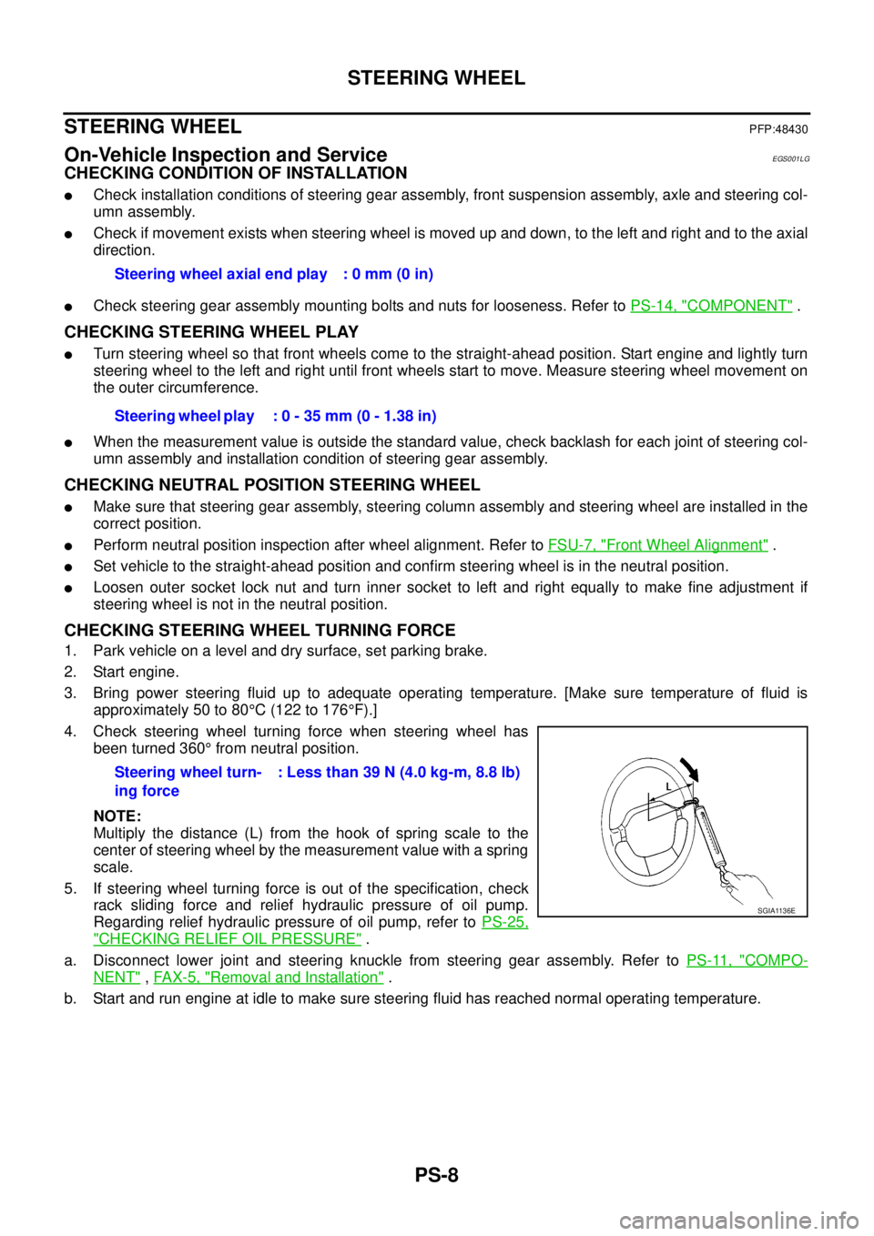
4. Check steering wheel turning force when steering wheel has
been turned 360°from neutral position.
NOTE:
Multiply the distance (L) from the hook of spring scale to the
center of steering wheel by the measurement value with a spring
scale.
5. If steering wheel turning force is out of the specification, check
rack sliding force and relief hydraulic pressure of oil pump.
Regarding relief hydraulic pressure of oil pump, refer toPS-25,
"CHECKING RELIEF OIL PRESSURE".
a. Disconnect lower joint and steering knuckle from steering gear assembly. Refer toPS-11, "
COMPO-
NENT",FAX-5, "Removal and Installation".
b. Start and run engine at idle to make sure steering fluid has reached normal operating temperature.Steering wheel axial end play : 0 mm (0 in)
Steering wheel play : 0 - 35 mm (0 - 1.38 in)
Steering wheel turn-
ing force: Less than 39 N (4.0 kg-m, 8.8 lb)
SGIA1136E
Page 2652 of 3171

POWER STEERING OIL PUMP
PS-25
C
D
E
F
H
I
J
K
L
MA
B
PS
POWER STEERING OIL PUMPPFP:49110
On-Vehicle Inspection and ServiceEGS001LL
CHECKING RELIEF OIL PRESSURE
CAUTION:
Make sure that belt tension is normal before starting the following procedure.
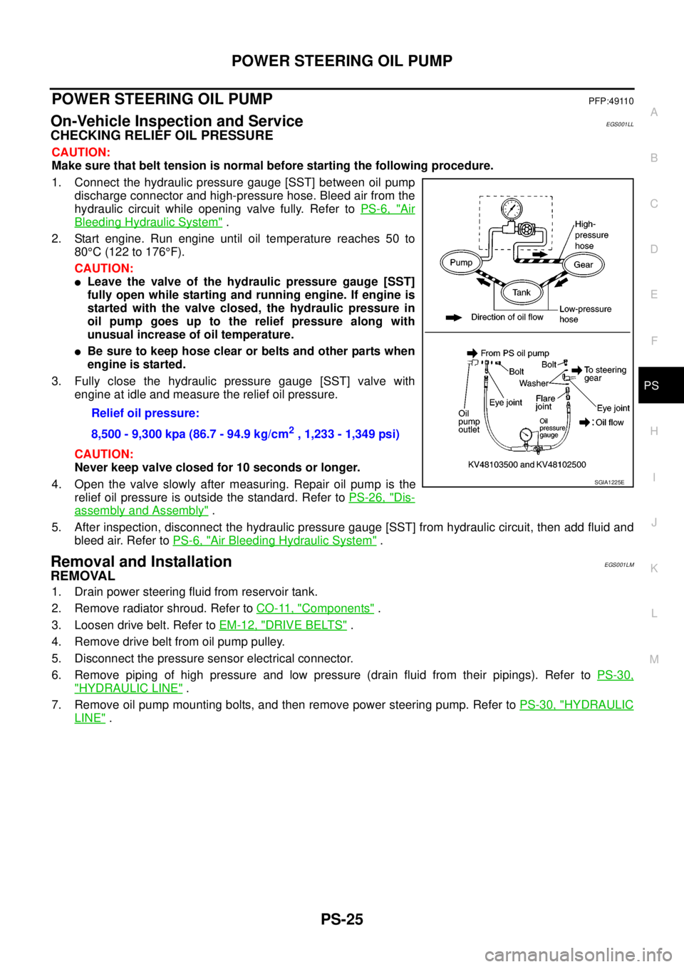
1. Connect the hydraulic pressure gauge [SST] between oil pump
discharge connector and high-pressure hose. Bleed air from the
hydraulic circuit while opening valve fully. Refer toPS-6, "
Air
Bleeding Hydraulic System".
2. Start engine. Run engine until oil temperature reaches 50 to
80°C(122to176°F).
CAUTION:
lLeave the valve of the hydraulic pressure gauge [SST]
fully open while starting and running engine. If engine is
started with the valve closed, the hydraulic pressure in
oil pump goes up to the relief pressure along with
unusual increase of oil temperature.
lBe sure to keep hose clear or belts and other parts when
engineisstarted.
3. Fully close the hydraulic pressure gauge [SST] valve with
engine at idle and measure the relief oil pressure.
CAUTION:
Never keep valve closed for 10 seconds or longer.
4. Open the valve slowly after measuring. Repair oil pump is the
relief oil pressure is outside the standard. Refer toPS-26, "
Dis-
assembly and Assembly".
5. After inspection, disconnect the hydraulic pressure gauge [SST] from hydraulic circuit, then add fluid and
bleed air. Refer toPS-6, "
Air Bleeding Hydraulic System".
Removal and InstallationEGS001LM
REMOVAL
1. Drain power steering fluid from reservoir tank.
2. Remove radiator shroud. Refer toCO-11, "
Components".
3. Loosen drive belt. Refer toEM-12, "
DRIVE BELTS".
4. Remove drive belt from oil pump pulley.
5. Disconnect the pressure sensor electrical connector.
6. Remove piping of high pressure and low pressure (drain fluid from their pipings). Refer toPS-30,
"HYDRAULIC LINE".
7. Remove oil pump mounting bolts, and then remove power steering pump. Refer toPS-30, "
HYDRAULIC
LINE". Relief oil pressure:
8,500 - 9,300 kpa (86.7 - 94.9 kg/cm
2, 1,233 - 1,349 psi)
SGIA1225E
Page 2661 of 3171

PS-34
SERVICE DATA AND SPECIFICATIONS (SDS)
SERVICE DATA AND SPECIFICATIONS (SDS)
PFP:00030
Steering WheelEGS001LR
Steering AngleEGS001LS
Steering ColumnEGS001LT
Steering Outer Socket and Inner SocketEGS001LU
Steering wheel axial end play 0 mm (0 in)
Steering wheel play 0 - 35 mm (0 - 1.38 in)
Inner wheel
Degree minute (Decimal degree)2WD 33°31¢-35°31¢(33.5°- 36.5°)
4WD 33°48¢-35°48¢(33.8°- 35.8°)
Outer wheel
Degree minute (Decimal degree)2WD 29°23¢-31°23¢(29.4°- 31.4°)
4WD 29°40¢-31°40¢(29.7°- 31.7°)
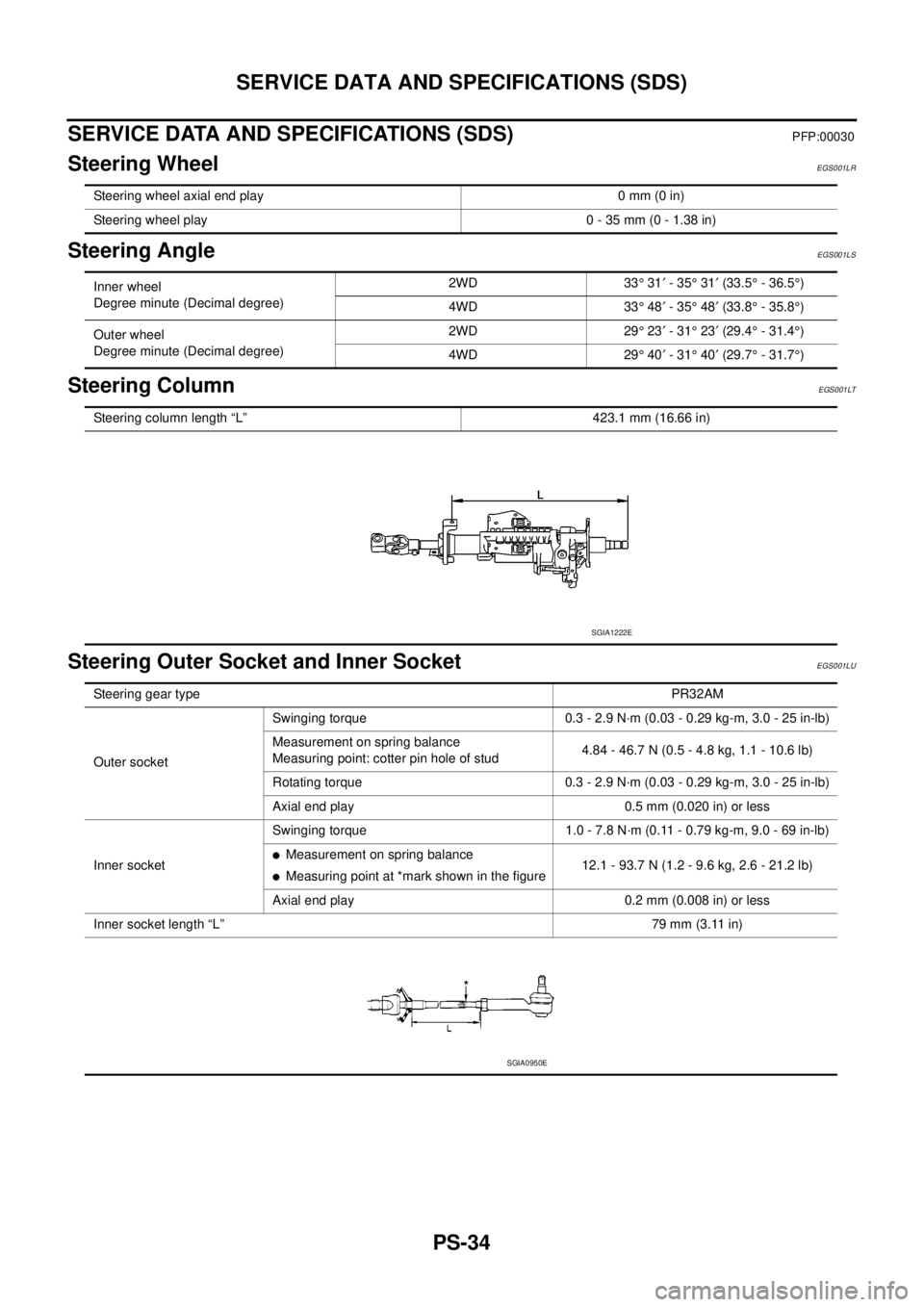
Steering column length “L” 423.1 mm (16.66 in)
SGIA1222E
Steering gear typePR32AM
Outer socketSwinging torque 0.3 - 2.9 N·m (0.03 - 0.29 kg-m, 3.0 - 25 in-lb)
Measurement on spring balance
Measuring point: cotter pin hole of stud4.84 - 46.7 N (0.5 - 4.8 kg, 1.1 - 10.6 lb)
Rotating torque 0.3 - 2.9 N·m (0.03 - 0.29 kg-m, 3.0 - 25 in-lb)
Axial end play 0.5 mm (0.020 in) or less
Inner socketSwinging torque 1.0 - 7.8 N·m (0.11 - 0.79 kg-m, 9.0 - 69 in-lb)
lMeasurement on spring balance
lMeasuring point at *mark shown in the figure12.1 - 93.7 N (1.2 - 9.6 kg, 2.6 - 21.2 lb)
Axial end play 0.2 mm (0.008 in) or less
Inner socket length “L”79 mm (3.11 in)
SGIA0950E
Page 2662 of 3171
SERVICE DATA AND SPECIFICATIONS (SDS)
PS-35
C
D
E
F
H
I
J
K
L
MA
B
PS
Steering GearEGS001LV
Oil PumpEGS001LW
Steering FluidEGS001LX
Steering gear modelPR32AM
Rack neutral position, dimension “L” (rack stroke) 84 mm (3.31 in)
SGIA0877E
Oil pump relief hydraulic pressure
8,500 - 9,300 kpa (86.7 - 94.9 kg/cm2, 1,233 - 1,349 psi)
Fluid capacity
Approx. 1.0 (1 - 1/8 US qt, 7/8 Imp qt)
Page 2663 of 3171
PS-36
SERVICE DATA AND SPECIFICATIONS (SDS)
Page 2664 of 3171

RAX-1
REAR AXLE
D DRIVELINE/AXLE
CONTENTS
C
E
F
G
H
I
J
K
L
M
SECTIONRAX
A
B
RAX
REAR AXLE
M226
PRECAUTIONS .......................................................... 2
Precautions .............................................................. 2
PREPARATION ........................................................... 3
Special Service Tools ............................................... 3
Commercial Service tools ........................................ 4
NOISE, VIBRATION, AND HARSHNESS (NVH)
TROUBLESHOOTING ................................................ 5
NVH Troubleshooting Chart ..................................... 5
ON-VEHICLE SERVICE ............................................. 6
Rear Axle Parts ........................................................ 6
Rear Axle Bearing .................................................... 6AXLE SHAFT .............................................................. 7
Removal and Installation .......................................... 7
REMOVAL ............................................................. 8
INSPECTION AFTER REMOVAL ......................... 9
INSTALLATION ..................................................... 9
DISASSEMBLY ..................................................... 9
INSPECTION AFTER DISASSEMBLY ................ 11
ASSEMBLY ......................................................... 11
AXLE BEARING ....................................................... 12
Removal and Installation ........................................ 12
AXLE OIL SEAL ....................................................... 13
Removal and Installation ........................................ 13
SERVICE DATA AND SPECIFICATIONS (SDS) ...... 14
Axle Bearing ........................................................... 14
Page 2666 of 3171
PREPARATION
RAX-3
[M226]
C
E
F
G
H
I
J
K
L
MA
B
RAX
PREPARATIONPFP:00002
Special Service ToolsEDS003HU
Tool number
Tool nameDescription
ST30031000
Bearing puller
a: 90 mm (3.54 in)
b: 50 mm (1.85 in)Removing axle shaft bearing
ST33290001
PullerRemoving axle shaft bearing cup
Removing rear oil seal
ST35271000
Rear axle oil seal drift
a: 72 mm (2.83 in)
b: 63 mm (2.84 in)Installing rear oil seal
NT411
NT713
NT115