Page 2405 of 3171

MTC-18
PREPARATION
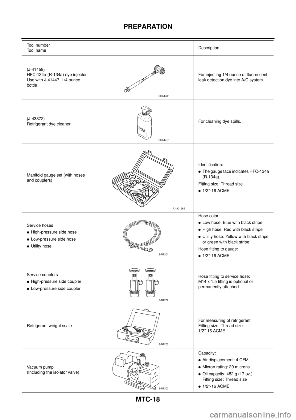
(J-41459)
HFC-134a (R-134a) dye injector
Use with J-41447, 1/4 ounce
bottleFor injecting 1/4 ounce of fluorescent
leak detection dye into A/C system.
(J-43872)
Refrigerant dye cleanerFor cleaning dye spills.
Manifold gauge set (with hoses
and couplers)Identification:
lThe gauge face indicates HFC-134a
(R-134a).
Fitting size: Thread size
l1/2²-16 ACME
Service hoses
lHigh-pressure side hose
lLow-pressure side hose
lUtility hoseHose color:
lLow hose: Blue with black stripe
lHigh hose: Red with black stripe
lUtility hose: Yellow with black stripe
or green with black stripe
Hose fitting to gauge:
l1/2²-16 ACME
Service couplers
lHigh-pressure side coupler
lLow-pressure side couplerHose fitting to service hose:
M14 x 1.5 fitting is optional or
permanently attached.
Refrigerant weight scaleFor measuring of refrigerant
Fitting size: Thread size
1/2²-16 ACME
Vacuum pump
(Including the isolator valve)Capacity:
lAir displacement: 4 CFM
lMicron rating: 20 microns
lOil capacity: 482 g (17 oz.)
Fitting size: Thread size
l1/2²-16 ACME Tool number
Tool nameDescription
SHA440F
SHA441F
RJIA0196E
S-NT201
S-NT202
S-NT200
S-NT203
Page 2406 of 3171
PREPARATION
MTC-19
C
D
E
F
G
H
I
K
L
MA
B
MTC
Commercial Service ToolsEJS00638
Tool number
Tool nameDescription
(J-44614)
Clutch disk holding toolClutch disk holding tool
WHA230
Page 2505 of 3171
MTC-118
REFRIGERANT LINES
REFRIGERANT LINES
PFP:92600
HFC-134a (R-134a) Service ProcedureEJS005HA
SETTING OF SERVICE TOOLS AND EQUIPMENT
Discharging Refrigerant
WARNING:
Avoid breathing A/C refrigerant and lubricant vapor or mist. Exposure may irritate eyes, nose and
throat. Use only approved recovery/recycling equipment to discharge HFC-134a (R-134a) refrigerant. If
accidental system discharge occurs, ventilate work area before resuming service. Additional health
and safety information may be obtained from refrigerant and lubricant manufacturers.
Evacuating System and Charging Refrigerant
1. Shut-off valve 2. A/C service valve 3. Recovery/Recycling equipment ACR 2000
(J-43600) with refrigerant identifier
WJIA0579E
1. Shut-off valve 2. A/C service valve 3. Recovery/Recycling equipment ACR
2000 (J-43600) with refrigerant identifier
4. Refrigerant container (HFC-134a) 5. Weight scale (J-39650) 6. Evacuating vacuum pump (J-39699)
7. Manifold gauge set (J-39183)
WJIA0580E
Page 2507 of 3171
MTC-120
REFRIGERANT LINES
Components
EJS005HB
A/C Compressor and Condenser —LHD Models—
MJIB0276E
1. High-pressure service valve 2. Clip 3. High-pressure A/C pipe
4. Refrigerant pressure sensor 5. Condenser 6. Compressor shaft seal
7. High-pressure flexible A/C hose 8. Low-pressure flexible A/C hose 9. Low-pressure service valve
10. Low-pressure A/C pipe 11. Expansion valve 12. A/C drain hose
Page 2508 of 3171
REFRIGERANT LINES
MTC-121
C
D
E
F
G
H
I
K
L
MA
B
MTC
A/C Compressor and Condenser —RHD Models—
MJIB0277E
1. High-pressure service valve 2. Clip 3. High-pressure A/C pipe
4. Refrigerant pressure sensor 5. Condenser 6. Compressor shaft seal
7. High-pressure flexible A/C hose 8. Low-pressure flexible A/C hose 9. Low-pressure service valve
10. Low-pressure A/C pipe 11. Expansion valve 12. A/C drain hose
Page 2509 of 3171

MTC-122
REFRIGERANT LINES
Removal and Installation for Compressor
EJS005HC
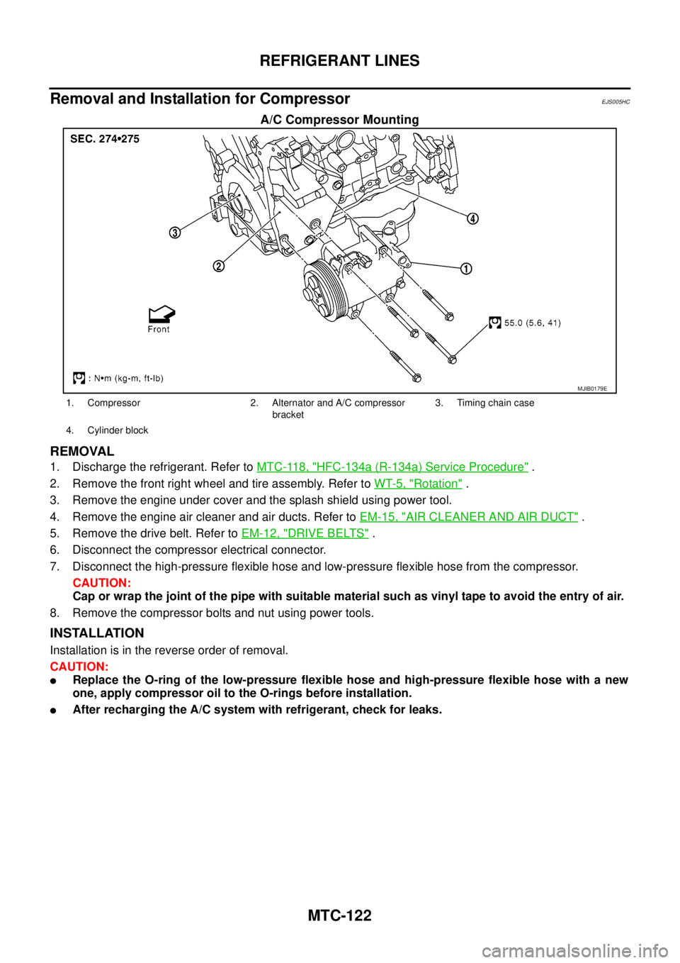
A/C Compressor Mounting
REMOVAL
1. Discharge the refrigerant. Refer toMTC-118, "HFC-134a (R-134a) Service Procedure".
2. Remove the front right wheel and tire assembly. Refer toWT-5, "
Rotation".
3. Remove the engine under cover and the splash shield using power tool.
4. Remove the engine air cleaner and air ducts. Refer toEM-15, "
AIR CLEANER AND AIR DUCT".
5. Remove the drive belt. Refer toEM-12, "
DRIVE BELTS".
6. Disconnect the compressor electrical connector.
7. Disconnect the high-pressure flexible hose and low-pressure flexible hose from the compressor.
CAUTION:
Cap or wrap the joint of the pipe with suitable material such as vinyl tape to avoid the entry of air.
8. Remove the compressor bolts and nut using power tools.
INSTALLATION
Installation is in the reverse order of removal.
CAUTION:
lReplace the O-ring of the low-pressure flexible hose and high-pressure flexible hose with a new
one, apply compressor oil to the O-rings before installation.
lAfter recharging the A/C system with refrigerant, check for leaks.
MJIB0179E
1. Compressor 2. Alternator and A/C compressor
bracket3. Timing chain case
4. Cylinder block
Page 2513 of 3171

MTC-126
REFRIGERANT LINES
BREAK-IN OPERATION
When replacing compressor clutch assembly, always conduct the break-in operation. This is done by engag-
ing and disengaging the clutch about 30 times. Break-in operation raises the level of transmitted torque.
Removal and Installation for Low-pressure Flexible HoseEJS005HE
REMOVAL
1. Remove the engine room cover using power tools.
2. Remove the engine air cleaner and air ducts. Refer toEM-15, "
AIR CLEANER AND AIR DUCT".
3. Remove the cowl top extension. Refer toEI-20, "
COWL TOP".
4. Discharge the refrigerant. Refer toMTC-118, "
HFC-134a (R-134a) Service Procedure".
CAUTION:
Cap or wrap the joint of the pipe with suitable material such as vinyl tape to avoid the entry of air.
5. Remove the low-pressure flexible hose. Refer toMTC-120, "
Components".
INSTALLATION
Installation is in the reverse order of removal.
Refer toMTC-120, "
Components".
CAUTION:
lReplace the O-ring of the low-pressure flexible hose with a new one, then apply compressor oil to
it when installing it.
lAfter charging refrigerant, check for leaks.
Removal and Installation for High-pressure Flexible HoseEJS005HF
REMOVAL
1. Remove the engine under cover.
2. Remove the engine air cleaner and air ducts. Refer toEM-15, "
AIR CLEANER AND AIR DUCT"
3. Discharge the refrigerant. Refer toMTC-118, "HFC-134a (R-134a) Service Procedure".
4. Remove the high-pressure flexible hose. Refer toMTC-120, "
Components".
CAUTION:
Cap or wrap the joint of the pipe with suitable material such as vinyl tape to avoid the entry of air.
INSTALLATION
Installation is in the reverse order of removal.
Refer toMTC-120, "
Components".
CAUTION:
lReplace the O-ring of the high-pressure flexible hose with a new one, then apply compressor oil to
it when installing it.
lAfter charging refrigerant, check for leaks.
Removal and Installation for High-pressure PipeEJS005HG
REMOVAL
1. Remove the cowl top extension. Refer toEI-20, "COWL TOP".
2. Disconnect the battery negative cable.
3. Reposition the IPDM E/R aside.
4. Remove the front right wheel and tire assembly. Refer toWT-5, "
Rotation".
5. Position aside the front floor insulator.
6. Discharge the refrigerant. Refer toMTC-118, "
HFC-134a (R-134a) Service Procedure".
7. Remove the low pressure pipe. Refer toMTC-127, "
Removal and Installation for Low-pressure Pipe".
8. Remove the high-pressure pipe. Refer toMTC-120, "
Components".
CAUTION:
Cap or wrap the joint of the pipe with suitable material such as vinyl tape to avoid the entry of air.
INSTALLATION
Installation is in the reverse order of removal.
Refer toMTC-120, "
Components".
Page 2514 of 3171

REFRIGERANT LINES
MTC-127
C
D
E
F
G
H
I
K
L
MA
B
MTC
CAUTION:
lReplace the O-ring of the high-pressure pipe with a new one, then apply compressor oil to it when
installing it.
lAfter charging refrigerant, check for leaks.
Removal and Installation for Low-pressure PipeEJS005HH
REMOVAL
1. Discharge the refrigerant. Refer toMTC-118, "HFC-134a (R-134a) Service Procedure".
2. Remove the cowl top and the cowl top extension. Refer toEI-20, "
COWL TOP".
3. Remove the low-pressure pipe. Refer toMTC-120, "
Components".
CAUTION:
Cap or wrap the joint of the pipes with suitable material such as vinyl tape to avoid the entry of air.
INSTALLATION
Installation is in the reverse order of removal.
Refer toMTC-120, "
Components".
CAUTION:
lReplace the O-ring of the high/low-pressure pipe with a new one, then apply compressor oil to it
when installing it.
lAfter charging refrigerant, check for leaks.
Removal and Installation for Refrigerant Pressure SensorEJS005HI
REMOVAL
1. Discharge the refrigerant. Refer toMTC-118, "HFC-134a (R-134a) Service Procedure".
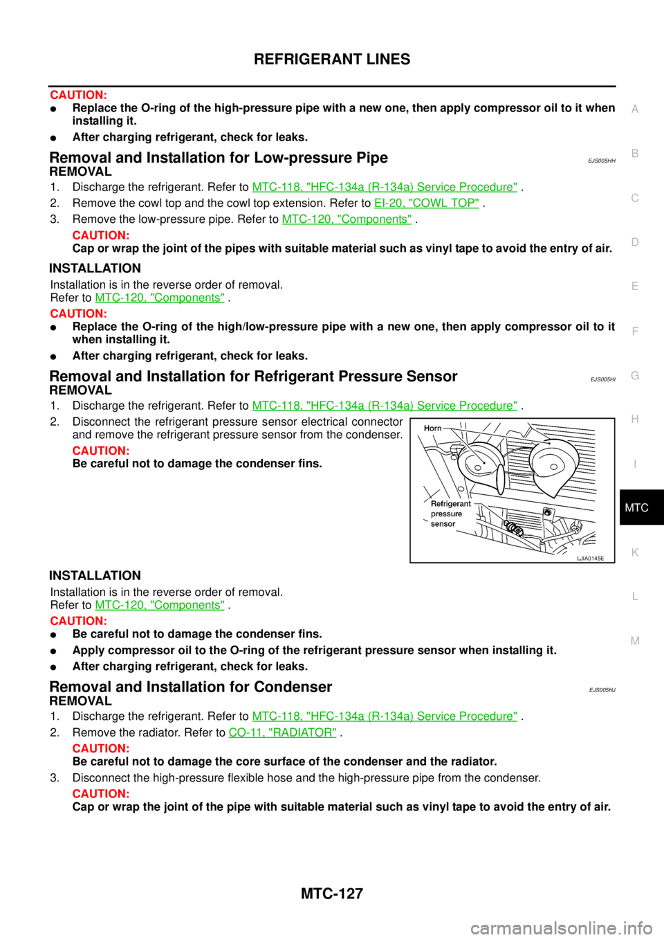
2. Disconnect the refrigerant pressure sensor electrical connector
and remove the refrigerant pressure sensor from the condenser.
CAUTION:
Be careful not to damage the condenser fins.
INSTALLATION
Installation is in the reverse order of removal.
Refer toMTC-120, "
Components".
CAUTION:
lBe careful not to damage the condenser fins.
lApply compressor oil to the O-ring of the refrigerant pressure sensor when installing it.
lAfter charging refrigerant, check for leaks.
Removal and Installation for CondenserEJS005HJ
REMOVAL
1. Discharge the refrigerant. Refer toMTC-118, "HFC-134a (R-134a) Service Procedure".
2. Remove the radiator. Refer toCO-11, "
RADIATOR".
CAUTION:
Be careful not to damage the core surface of the condenser and the radiator.
3. Disconnect the high-pressure flexible hose and the high-pressure pipe from the condenser.
CAUTION:
Cap or wrap the joint of the pipe with suitable material such as vinyl tape to avoid the entry of air.
LJIA0145E