2005 NISSAN NAVARA service
[x] Cancel search: servicePage 2532 of 3171
PRECAUTIONS
PG-3
C
D
E
F
G
H
I
J
L
MA
B
PG
PRECAUTIONSPFP:00011
Precautions for Supplemental Restraint System (SRS) “AIR BAG” and “SEAT
BELT PRE-TENSIONER”
EKS00N4A
The Supplemental Restraint System such as “AIR BAG” and “SEAT BELT PRE-TENSIONER”, used along
with a front seat belt, helps to reduce the risk or severity of injury to the driver and front passenger for certain
types of collision. Information necessary to service the system safely is included in the SRS and SB section of
this Service Manual.
WARNING:
lTo avoid rendering the SRS inoperative, which could increase the risk of personal injury or death
in the event of a collision which would result in air bag inflation, all maintenance must be per-
formed by an authorized NISSAN/INFINITI dealer.
lImproper maintenance, including incorrect removal and installation of the SRS, can lead to per-
sonal injury caused by unintentional activation of the system. For removal of Spiral Cable and Air
Bag Module, see the SRS section.
lDo not use electrical test equipment on any circuit related to the SRS unless instructed to in this
Service Manual. SRS wiring harnesses can be identified by yellow and/or orange harnesses or
harness connectors.
Wiring Diagrams and Trouble DiagnosisEKS00LIU
When you read wiring diagrams, refer to the following:
lRefer toGI-15, "HowtoReadWiringDiagrams"in GI section.
lRefer toPG-4, "POWER SUPPLY ROUTING CIRCUIT"for power distribution.
When you perform trouble diagnosis, refer to the following:
lRefer toGI-11, "HOW TO FOLLOW TEST GROUPS IN TROUBLE DIAGNOSES"in GI section.
lRefer toGI-24, "How to Perform Efficient Diagnosis for an Electrical Incident"in GI section.
Page 2616 of 3171
PR-1
PROPELLER SHAFT
D DRIVELINE/AXLE
CONTENTS
C
E
F
G
H
I
J
K
L
M
SECTIONPR
A
B
PR
PROPELLER SHAFT
NOISE, VIBRATION, AND HARSHNESS (NVH)
TROUBLESHOOTING ................................................ 2
NVH Troubleshooting Chart ..................................... 2
FRONT PROPELLER SHAFT .................................... 3
On-Vehicle Service ................................................... 3
APPEARANCE AND NOISE INSPECTION .......... 3
PROPELLER SHAFT VIBRATION ........................ 3
Removal and Installation .......................................... 4
COMPONENTS .................................................... 4
REMOVAL ............................................................. 4
INSPECTION ........................................................ 4
INSTALLATION ..................................................... 5
Disassembly and Assembly ..................................... 5
DISASSEMBLY ..................................................... 5
ASSEMBLY ........................................................... 6
REAR PROPELLER SHAFT ...................................... 7On-Vehicle Service ................................................... 7
APPEARANCE AND NOISE INSPECTION .......... 7
PROPELLER SHAFT VIBRATION ........................ 7
Removal and Installation .......................................... 8
COMPONENTS (2WD) ......................................... 8
COMPONENTS (4WD) ......................................... 8
REMOVAL ............................................................. 9
INSPECTION ........................................................ 9
INSTALLATION ................................................... 10
Disassembly and Assembly .................................... 10
DISASSEMBLY ................................................... 10
ASSEMBLY ......................................................... 11
SERVICE DATA AND SPECIFICATIONS (SDS) ...... 12
General Specifications ............................................ 12
Snap Ring ............................................................... 12
Page 2618 of 3171
FRONT PROPELLER SHAFT
PR-3
C
E
F
G
H
I
J
K
L
MA
B
PR
FRONT PROPELLER SHAFTPFP:37200
On-Vehicle ServiceEDS002WO
APPEARANCE AND NOISE INSPECTION
lCheck the propeller shaft tube surface for dents or cracks. If damaged, replace the propeller shaft assem-
bly.
lCheck the bearings for noise and damage. Repair or replace the bearings as necessary.
PROPELLER SHAFT VIBRATION
If a vibration is present at high speed, inspect the propeller shaft runout first.
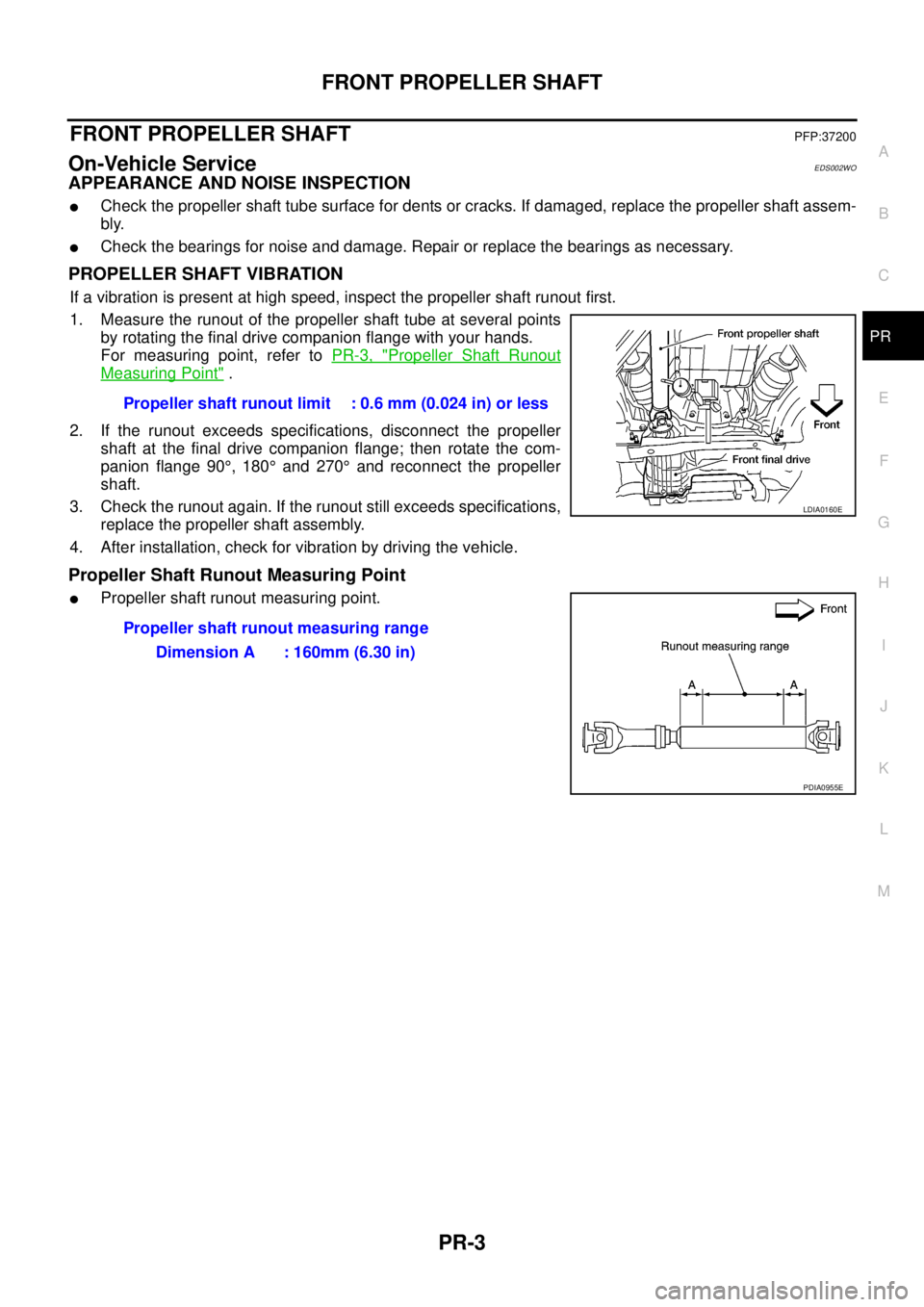
1. Measure the runout of the propeller shaft tube at several points
by rotating the final drive companion flange with your hands.
For measuring point, refer toPR-3, "
Propeller Shaft Runout
Measuring Point".
2. If the runout exceeds specifications, disconnect the propeller
shaft at the final drive companion flange; then rotate the com-
panion flange 90°,180°and 270°and reconnect the propeller
shaft.
3. Check the runout again. If the runout still exceeds specifications,
replace the propeller shaft assembly.
4. After installation, check for vibration by driving the vehicle.
Propeller Shaft Runout Measuring Point
lPropeller shaft runout measuring point.Propeller shaft runout limit : 0.6 mm (0.024 in) or less
LDIA0160E
Propeller shaft runout measuring range
Dimension A : 160mm (6.30 in)
PDIA0955E
Page 2622 of 3171
REAR PROPELLER SHAFT
PR-7
C
E
F
G
H
I
J
K
L
MA
B
PR
REAR PROPELLER SHAFTPFP:37000
On-Vehicle ServiceEDS002WR
APPEARANCE AND NOISE INSPECTION
lCheck the propeller shaft tube surface for dents or cracks. If damaged, replace the propeller shaft assem-
bly.
lCheck the bearings for noise and damage. Repair or replace the bearings as necessary.
PROPELLER SHAFT VIBRATION
If a vibration is present at high speed, inspect the propeller shaft runout first.
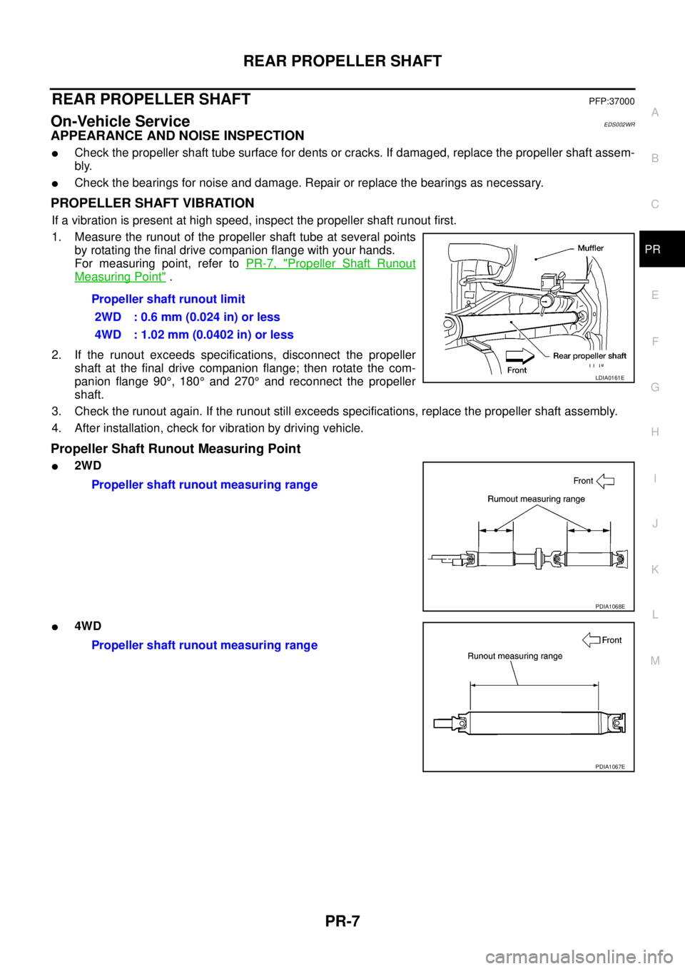
1. Measure the runout of the propeller shaft tube at several points
by rotating the final drive companion flange with your hands.
For measuring point, refer toPR-7, "
Propeller Shaft Runout
Measuring Point".
2. If the runout exceeds specifications, disconnect the propeller
shaft at the final drive companion flange; then rotate the com-
panion flange 90°,180°and 270°and reconnect the propeller
shaft.
3. Check the runout again. If the runout still exceeds specifications, replace the propeller shaft assembly.
4. After installation, check for vibration by driving vehicle.
Propeller Shaft Runout Measuring Point
l2WD
l4WDPropeller shaft runout limit
2WD : 0.6 mm (0.024 in) or less
4WD : 1.02 mm (0.0402 in) or less
LDIA0161E
Propeller shaft runout measuring range
PDIA1068E
Propeller shaft runout measuring range
PDIA1067E
Page 2627 of 3171

PR-12
SERVICE DATA AND SPECIFICATIONS (SDS)
SERVICE DATA AND SPECIFICATIONS (SDS)
PFP:00030
General SpecificationsEDS0035N
2WD Models
4WD Models
Snap RingEDS0035O
Model 2S1330
Unit: mm (in)
*Always check with the Parts Department for the latest parts information.
Model 2F S1300 and 3S S1310
Unit: mm (in)
*Always check with the Parts Department for the latest parts information.Applied modelYD25DDTi
6M/T 5A/T
Propeller shaft model 3S S1310
Number of joints3
Coupling method with rear final drive Flange type
Coupling method with transmission Sleeve type
1st Shaft length (Center bearing to spider) 675 mm (26.57 in) 742 mm (29.21 in)
2nd Shaft length (Spider to spider) 897 mm (35.31 in)
Shaft outer diameter 75.64 mm (2.9779 in)
Journal axial play 0.02 mm (0.0008 in) or less
Propeller shaft run out limit 0.6 mm (0.024 in) or less
Propeller shaft joint flex effort 1.96 N·m (0.20 kg-m, 17 in-lb) or less
Applied modelYD25DDTi
Propeller shaft modelFront Rear
2F S1300 2S1330 (aluminum tube)
Number of joints2
Coupling method with front final drive Flange type
Coupling method with transfer Flange type Sleeve type
Shaft length (Spider to spider) 718 mm (28.27 in) 1266.8 mm (35.51 in)
Shaft outer diameter 65 mm (2.56 in) 102.5 mm (2.97 in)
Journal axial play 0.02 mm (0.0008 in) or less
Propeller shaft run out limit 0.6 mm (0.024 in) or less 1.02 mm (0.0402 in) or less
Propeller shaft joint flex effort 1.96 N·m (0.20 kg-m, 17 in-lb) or less 2.26 N·m (0.23 kg-m, 20 in-lb) or less
Thickness Part number* Thickness Part number*
1.600 - 1.638 (0.0630 - 0.0645)
1.549 - 1.588 (0.0610 - 0.0625)37146-7S000
37147-7S0001.524 - 1.562 (0.0600 - 0.0615)
1.499 - 1.537 (0.0590 - 0.0605)37148-7S000
37149-7S000
Thickness Part number* Thickness Part number*
1.45 (0.0571)
1.50 (0.0591)
1.55 (0.0610)
1.60 (0.0630)37146 7F000
37147 7F000
37148 7F000
37149 7F0001.65 (0.0650)
1.70 (0.0669)
1.75 (0.0689)37150 7F000
37151 7F000
37152 7F000
Page 2628 of 3171
PS-1
POWER STEERING SYSTEM
G STEERING
CONTENTS
C
D
E
F
H
I
J
K
L
M
SECTIONPS
A
B
PS
POWER STEERING SYSTEM
PRECAUTIONS .......................................................... 2
Precautions for Supplemental Restraint System
(SRS)“AIRBAG”and“SEATBELTPRE-TEN-
SIONER” .................................................................. 2
Precautions for Steering System .............................. 2
PREPARATION ........................................................... 3
Special Service Tools [SST] ..................................... 3
Commercial Service Tools ........................................ 4
NOISE, VIBRATION, AND HARSHNESS (NVH)
TROUBLESHOOTING ................................................ 5
NVH Troubleshooting Chart ..................................... 5
POWER STEERING FLUID ........................................ 6
Checking Fluid Level ................................................ 6
Checking Fluid Leakage ........................................... 6
Air Bleeding Hydraulic System ................................. 6
STEERING WHEEL .................................................... 8
On-Vehicle Inspection and Service .......................... 8
CHECKING CONDITION OF INSTALLATION ...... 8
CHECKING STEERING WHEEL PLAY ................ 8
CHECKING NEUTRAL POSITION STEERING
WHEEL ................................................................. 8
CHECKING STEERING WHEEL TURNING
FORCE .................................................................. 8
CHECKING FRONT WHEEL TURNING ANGLE..... 9
Removal and Installation ........................................ 10
REMOVAL ........................................................... 10
INSTALLATION ................................................... 10
STEERING COLUMN ................................................11
Removal and Installation ......................................... 11
COMPONENT ...................................................... 11
REMOVAL ............................................................ 11
INSPECTION AFTER REMOVAL ....................... 12
INSTALLATION ................................................... 12
INSPECTION AFTER INSTALLATION ............... 13
POWER STEERING GEAR AND LINKAGE ............ 14Removal and Installation ........................................ 14
COMPONENT ..................................................... 14
REMOVAL ........................................................... 14
INSTALLATION ................................................... 15
INSPECTION AFTER INSTALLATION ................ 15
Disassembly and Assembly .................................... 16
COMPONENT ..................................................... 16
DISASSEMBLY ................................................... 17
INSPECTION AFTER DISASSEMBLY ................ 18
ASSEMBLY ......................................................... 20
POWER STEERING OIL PUMP ............................... 25
On-Vehicle Inspection and Service ......................... 25
CHECKING RELIEF OIL PRESSURE ................ 25
Removal and Installation ........................................ 25
REMOVAL ........................................................... 25
INSTALLATION ................................................... 26
Disassembly and Assembly .................................... 26
COMPONENT ..................................................... 26
INSPECTION BEFORE DISASSEMBLY ............. 26
DISASSEMBLY ................................................... 27
INSPECTION AFTER DISASSEMBLY ................ 27
ASSEMBLY ......................................................... 28
HYDRAULIC LINE .................................................... 30
Component (RHD Models) ..................................... 30
Component (LHD Models) ...................................... 32
Removal and Installation ........................................ 33
SERVICE DATA AND SPECIFICATIONS (SDS) ...... 34
Steering Wheel ....................................................... 34
Steering Angle ........................................................ 34
Steering Column ..................................................... 34
Steering Outer Socket and Inner Socket ................ 34
Steering Gear ......................................................... 35
Oil Pump ................................................................. 35
Steering Fluid .......................................................... 35
Page 2629 of 3171
PS-2
PRECAUTIONS
PRECAUTIONS
PFP:00001
Precautions for Supplemental Restraint System (SRS) “AIR BAG” and “SEAT
BELT PRE-TENSIONER”
EGS001M0
The Supplemental Restraint System such as “AIR BAG” and “SEAT BELT PRE-TENSIONER”, used along
with a front seat belt, helps to reduce the risk or severity of injury to the driver and front passenger for certain
types of collision. Information necessary to service the system safely is included in the SRS and SB section of
this Service Manual.
WARNING:
lTo avoid rendering the SRS inoperative, which could increase the risk of personal injury or death
in the event of a collision which would result in air bag inflation, all maintenance must be per-
formed by an authorized NISSAN/INFINITI dealer.
lImproper maintenance, including incorrect removal and installation of the SRS, can lead to per-
sonal injury caused by unintentional activation of the system. For removal of Spiral Cable and Air
Bag Module, see the SRS section.
lDo not use electrical test equipment on any circuit related to the SRS unless instructed to in this
Service Manual. SRS wiring harnesses can be identified by yellow and/or orange harnesses or
harness connectors.
Precautions for Steering SystemEGS001L9
lIn case of removing steering gear assembly, make the final tightening with grounded and unloaded vehi-
cle condition, and then check wheel alignment.
lObserve the following precautions when disassembling.
–Before disassembly, thoroughly clean the outside of the unit.
–Disassembly should be done in a clean work area. It is important to prevent the internal parts from becom-
ing contaminated by dirt or other foreign matter.
–For easier and proper assembly, place disassembled parts in order on a parts rack.
–Use nylon cloth or paper towels to clean the parts; common shop rags can leave lint that might interfere
with their operation.
–Do not reuse non-reusable parts.
–Before assembling, apply the specified grease to the directed parts.
Page 2630 of 3171
![NISSAN NAVARA 2005 Repair Workshop Manual PREPARATION
PS-3
C
D
E
F
H
I
J
K
L
MA
B
PS
PREPARATIONPFP:00002
Special Service Tools [SST]EGS001LA
Tool number
Tool nameDescription
ST27180001
Steering wheel pullerRemoving steering wheel
ST3127 S000 NISSAN NAVARA 2005 Repair Workshop Manual PREPARATION
PS-3
C
D
E
F
H
I
J
K
L
MA
B
PS
PREPARATIONPFP:00002
Special Service Tools [SST]EGS001LA
Tool number
Tool nameDescription
ST27180001
Steering wheel pullerRemoving steering wheel
ST3127 S000](/manual-img/5/57362/w960_57362-2629.png)
PREPARATION
PS-3
C
D
E
F
H
I
J
K
L
MA
B
PS
PREPARATIONPFP:00002
Special Service Tools [SST]EGS001LA
Tool number
Tool nameDescription
ST27180001
Steering wheel pullerRemoving steering wheel
ST3127 S000
Preload gauge
1. GG9103000
Torque wrench
2. HT62940000
Socket adapter
3. HT62900000
Socket adapterInspecting of rotating torque for ball joint
KV489Q0030
Rear cover wrench
a: 19 mm (0.75 in)
b: 34.9 mm (1.374 in)Removing and installing rear cover
KV489Q0020
Teflon ring correcting tool
a: 50 mm (1.97 in) dia.
b: 36 mm (1.42 in) dia.
c: 100 mm (3.94 in) dia.Installing rack Teflon ring
KV48103400
Preload adapterInspecting rotating torque
KV48103500
Pressure gaugeMeasuring oil pump relief pressure
KV48102500
Pressure gauge adapterMeasuring oil pump relief pressure
S-NT544
S-NT541
SGIA0516E
S-NT550
ZZA0824D
S-NT547
S-NT542