2005 NISSAN NAVARA service
[x] Cancel search: servicePage 2322 of 3171

PREPARATION
MT-5
D
E
F
G
H
I
J
K
L
MA
B
MT
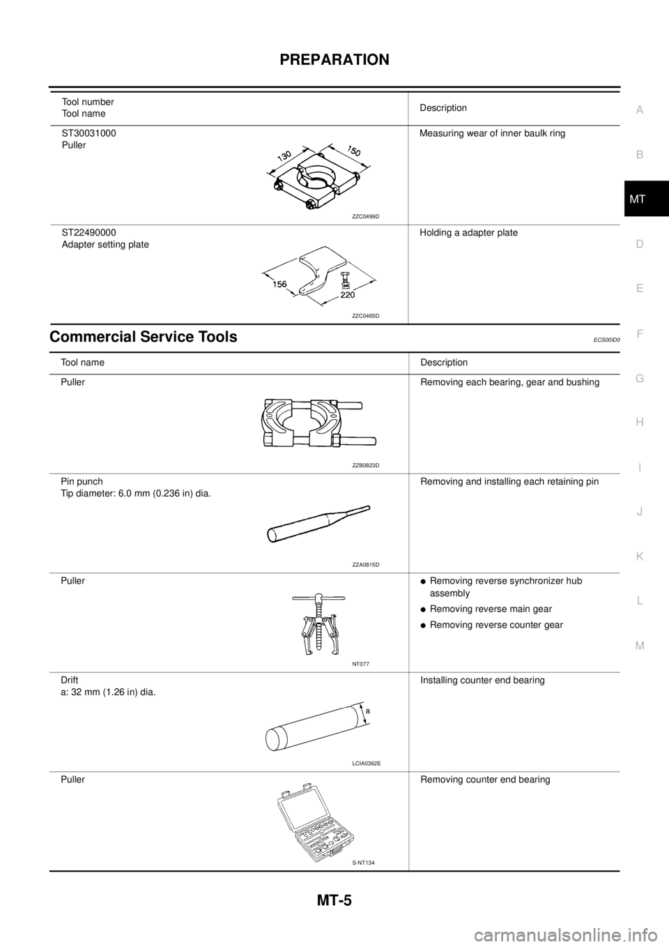
Commercial Service ToolsECS00ID0
ST30031000
PullerMeasuring wear of inner baulk ring
ST22490000
Adapter setting plateHolding a adapter plate Tool number
Tool nameDescription
ZZC0499D
ZZC0465D
Tool nameDescription
PullerRemoving each bearing, gear and bushing
Pin punch
Tipdiameter:6.0mm(0.236in)dia.Removing and installing each retaining pin
Puller
lRemoving reverse synchronizer hub
assembly
lRemoving reverse main gear
lRemoving reverse counter gear
Drift
a: 32 mm (1.26 in) dia.Installing counter end bearing
PullerRemoving counter end bearing
ZZB0823D
ZZA0815D
NT077
LCIA0362E
S-NT134
Page 2384 of 3171

SERVICE DATA AND SPECIFICATIONS (SDS)
MT-67
D
E
F
G
H
I
J
K
L
MA
B
MT
SERVICE DATA AND SPECIFICATIONS (SDS)PFP:00030
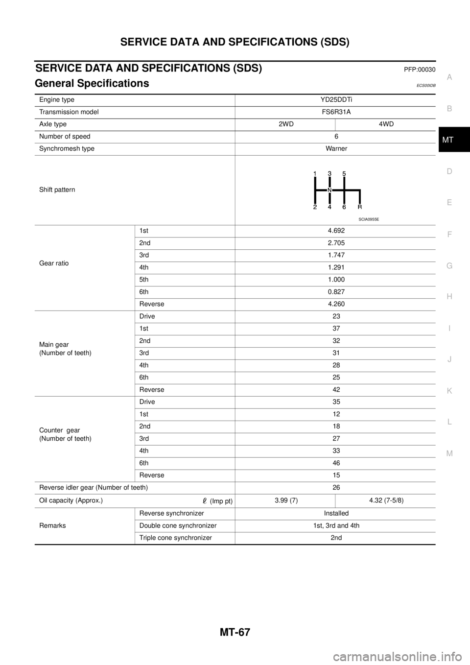
General SpecificationsECS00IDB
Engine typeYD25DDTi
Transmission modelFS6R31A
Axle type 2WD 4WD
Number of speed6
Synchromesh typeWarner
Shift pattern
Gear ratio1st 4.692
2nd 2.705
3rd 1.747
4th 1.291
5th 1.000
6th 0.827
Reverse 4.260
Main gear
(Number of teeth)Drive 23
1st 37
2nd 32
3rd 31
4th 28
6th 25
Reverse 42
Counter gear
(Number of teeth)Drive 35
1st 12
2nd 18
3rd 27
4th 33
6th 46
Reverse 15
Reverse idler gear (Number of teeth) 26
Oil capacity (Approx.)
(Imp pt)3.99 (7) 4.32 (7-5/8)
RemarksReverse synchronizer Installed
Double cone synchronizer 1st, 3rd and 4th
Triple cone synchronizer 2nd
SCIA0955E
Page 2385 of 3171

MT-68
SERVICE DATA AND SPECIFICATIONS (SDS)
Gear End Play
ECS00IDC
Unit: mm (in)
Snap RingsECS00IDD
Unit: mm (in)
*: Always check with the Parts Department for the latest parts information.Item Standard value
Counter gear0 - 0.10 (0 - 0.004)
Main drive gear0 - 0.10 (0 - 0.004)
Mainshaft (Front side) 0 - 0.10 (0 - 0.004)
Mainshaft (Rear side) 0 - 0.10 (0 - 0.004)
Selective parts Thickness Part number*
Main drive gear1.89 (0.0744)
1.95 (0.0768)
1.99 (0.0783)
2.03 (0.0799)
2.07 (0.0815)
2.11 (0.0831)32204 01G60
32204 01G61
32204 01G62
32204 01G63
32204 01G64
32204 01G65
Counter gear1.96 (0.0772)
2.02 (0.0795)
2.08 (0.0819)
2.14 (0.0843)
2.20 (0.0866)
2.26 (0.0890)
2.32 (0.0913)
2.38 (0.0937)
2.44 (0.0961)
2.50 (0.0984)
2.56 (0.1008)
2.62 (0.1031)32236 CD000
32236 CD001
32236 CD002
32236 CD003
32236 CD004
32236 CD005
32236 CD006
32236 CD007
32236 CD008
32236 CD009
32236 CD010
32236 CD011
MainshaftFront side2.08 (0.0819)
2.14 (0.0843)
2.20 (0.0866)
2.26 (0.0890)32204 CD000
32204 CD001
32204 CD002
32204 CD003
Rear side2.08 (0.0819)
2.14 (0.0843)
2.20 (0.0866)
2.26 (0.0890)
2.32 (0.0913)
2.38 (0.0937)
2.44 (0.0961)
2.50 (0.0984)
2.56 (0.1008)
2.62 (0.1031)
2.68 (0.1055)
2.74 (0.1079)
2.80 (0.1102)
2.86 (0.1126)
2.92 (0.1150)
2.98 (0.1173)32204 CD000
32204 CD001
32204 CD002
32204 CD003
32204 CD004
32204 CD005
32204 CD006
32204 CD007
32204 CD008
32204 CD009
32204 CD010
32204 CD011
32204 CD012
32204 CD013
32204 CD014
32204 CD015
Page 2386 of 3171

SERVICE DATA AND SPECIFICATIONS (SDS)
MT-69
D
E
F
G
H
I
J
K
L
MA
B
MT
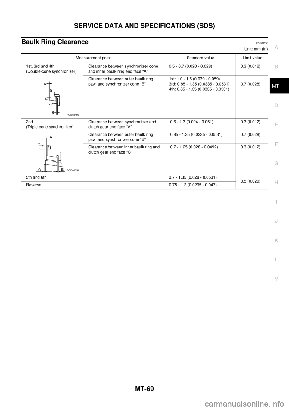
Baulk Ring ClearanceECS00IDE
Unit: mm (in)
Measurement point Standard value Limit value
1st, 3rd and 4th
(Double-cone synchronizer)Clearance between synchronizer cone
and inner baulk ring end face “A”0.5 - 0.7 (0.020 - 0.028) 0.3 (0.012)
Clearance between outer baulk ring
pawl and synchronizer cone “B”1st: 1.0 - 1.5 (0.039 - 0.059)
3rd: 0.85 - 1.35 (0.0335 - 0.0531)
4th: 0.85 - 1.35 (0.0335 - 0.0531)0.7 (0.028)
2nd
(Triple-cone synchronizer)Clearance between synchronizer and
clutch gear end face “A”0.6 - 1.3 (0.024 - 0.051) 0.3 (0.012)
Clearance between outer baulk ring
pawl and synchronizer cone “B”0.85 - 1.35 (0.0335 - 0.0531) 0.7 (0.028)
Clearance between inner baulk ring and
clutch gear end face “C”0.7 - 1.25 (0.028 - 0.0492) 0.3 (0.012)
5th and 6th 0.7 - 1.35 (0.028 - 0.0531)
0.5 (0.020)
Reverse 0.75 - 1.2 (0.0295 - 0.047)
PCIB0249E
PCIB0835J
Page 2387 of 3171

MT-70
SERVICE DATA AND SPECIFICATIONS (SDS)
Page 2388 of 3171

MTC-1
MANUAL AIR CONDITIONER
J AIR CONDITIONER
CONTENTS
C
D
E
F
G
H
I
K
L
M
SECTIONMTC
A
B
MTC
MANUAL AIR CONDITIONER
PRECAUTIONS .......................................................... 4
Precautions for Supplemental Restraint System
(SRS)“AIRBAG”and“SEATBELTPRE-TEN-
SIONER” .................................................................. 4
Precautions for Working with HFC-134a (R-134a)..... 4
Contaminated Refrigerant ........................................ 4
General Refrigerant Precautions .............................. 5
Precautions for Refrigerant Connection ................... 5
ABOUT ONE-TOUCH JOINT ................................ 5
FEATURES OF NEW TYPE REFRIGERANT
CONNECTION ...................................................... 7
O-RING AND REFRIGERANT CONNECTION..... 9
Precautions for Servicing Compressor ................... 12
Precautions for Service Equipment ........................ 12
RECOVERY/RECYCLING EQUIPMENT ............ 12
ELECTRONIC LEAK DETECTOR ...................... 12
VACUUM PUMP ................................................. 13
MANIFOLD GAUGE SET .................................... 13
SERVICE HOSES ............................................... 13
SERVICE COUPLERS ........................................ 14
REFRIGERANT WEIGHT SCALE ...................... 14
CALIBRATING ACR4 WEIGHT SCALE .............. 14
CHARGING CYLINDER ...................................... 14
Precautions for Leak Detection Dye ....................... 14
IDENTIFICATION ................................................ 15
IDENTIFICATION LABEL FOR VEHICLE ........... 15
Wiring Diagrams and Trouble Diagnosis ................ 15
PREPARATION ......................................................... 16
Special Service Tools ............................................. 16
HFC-134a (R-134a) Service Tools and Equipment... 16
Commercial Service Tools ...................................... 19
REFRIGERATION SYSTEM ..................................... 20
Refrigerant Cycle ................................................... 20
REFRIGERANT FLOW ....................................... 20
FREEZE PROTECTION ..................................... 20
Refrigerant System Protection ............................... 20
REFRIGERANT PRESSURE SENSOR ............. 20
PRESSURE RELIEF VALVE ............................... 21
Component Layout ................................................. 22
REFRIGERATION SYSTEM ............................... 22LUBRICANT .............................................................. 24
Maintenance of Lubricant Quantity in Compressor... 24
LUBRICANT ........................................................ 24
CHECKING AND ADJUSTING ............................ 24
AIR CONDITIONER CONTROL ............................... 26
Description .............................................................. 26
Operation ................................................................ 26
AIR MIX DOOR CONTROL ................................. 26
BLOWER SPEED CONTROL ............................. 26
INTAKE DOORS CONTROL ............................... 26
MODE DOOR CONTROL ................................... 26
DEFROSTER DOOR CONTROL ........................ 26
MAGNET CLUTCH CONTROL ........................... 27
SELF-DIAGNOSTIC SYSTEM ............................ 27
Description of Control System ................................ 28
Control Operation ................................................... 28
DISPLAY SCREEN .............................................. 29
TEMPERATURE SWITCH (TEMPERATURE
CONTROL) (FRONT) .......................................... 29
RECIRCULATION () SWITCH ............................. 29
REAR WINDOW DEFOGGER SWITCH ............. 29
OFF SWITCH (BLOWER SPEED SET TO 0) ..... 29
A/C SWITCH ....................................................... 29
MODE SWITCH .................................................. 29
Discharge Air Flow ................................................. 30
FRONT ................................................................ 30
System Description ................................................. 31
SWITCHES AND THEIR CONTROL FUNCTION... 31
CAN Communication System Description .............. 32
TROUBLE DIAGNOSIS ............................................ 33
CONSULT-II ............................................................ 33
CONSULT-II BASIC OPERATION ....................... 33
DATA MONITOR ................................................. 34
How to Perform Trouble Diagnosis for Quick and
Accurate Repair ...................................................... 35
WORK FLOW ...................................................... 35
SYMPTOM TABLE .............................................. 35
Component Parts and Harness Connector Location... 36
ENGINE COMPARTMENT .................................. 36
FRONT PASSENGER COMPARTMENT ............ 37
Page 2390 of 3171

MTC-3
C
D
E
F
G
H
I
K
L
MA
B
MTC BLOWER MOTOR RESISTOR ................................112
Components .......................................................... 112
Removal and Installation ....................................... 112
REMOVAL .......................................................... 112
INSTALLATION .................................................. 112
DUCTS AND GRILLES ...........................................113
Components .......................................................... 113
Removal and Installation ....................................... 116
CENTER CONSOLE HEAT DUCT AND REAR
FINISHER ASSEMBLY GRILLE ........................ 116
DEFROSTER NOZZLE ...................................... 116
RH AND LH SIDE DEMISTER DUCT ................ 116
RH AND LH VENTILATOR DUCT ...................... 116
CENTER VENTILATOR DUCT .......................... 116
FLOOR DUCT .................................................... 116
GRILLES ............................................................ 116
REFRIGERANT LINES ............................................118
HFC-134a (R-134a) Service Procedure ................ 118
SETTING OF SERVICE TOOLS AND EQUIP-
MENT ................................................................. 118
Components ......................................................... 120
Removal and Installation for Compressor ............ 122
REMOVAL ......................................................... 122
INSTALLATION ................................................. 122
Removal and Installation for Compressor Clutch . 123
REMOVAL ......................................................... 123
INSPECTION .................................................... 124
INSTALLATION ................................................. 124
BREAK-IN OPERATION ................................... 126
Removal and Installation for Low-pressure Flexible
Hose ..................................................................... 126
REMOVAL ......................................................... 126
INSTALLATION ................................................. 126
Removal and Installation for High-pressure Flexible
Hose ..................................................................... 126
REMOVAL ......................................................... 126INSTALLATION .................................................126
Removal and Installation for High-pressure Pipe . 126
REMOVAL .........................................................126
INSTALLATION .................................................126
Removal and Installation for Low-pressure Pipe ..127
REMOVAL .........................................................127
INSTALLATION .................................................127
Removal and Installation for Refrigerant Pressure
Sensor ..................................................................127
REMOVAL .........................................................127
INSTALLATION .................................................127
Removal and Installation for Condenser ..............127
REMOVAL .........................................................127
INSTALLATION .................................................128
Removal and Installation for Evaporator ..............129
REMOVAL .........................................................130
INSTALLATION .................................................130
Removal and Installation for Expansion Valve ......130
REMOVAL .........................................................130
INSTALLATION .................................................130
Checking for Refrigerant Leaks ............................131
Checking System for Leaks Using the Fluorescent
Leak Detector .......................................................131
Dye Injection .........................................................131
Electronic Refrigerant Leak Detector ....................132
PRECAUTIONS FOR HANDLING LEAK
DETECTOR .......................................................132
CHECKING PROCEDURE ...............................133
SERVICE DATA AND SPECIFICATIONS (SDS) ....135
Service Data and Specifications (SDS) ................135
COMPRESSOR ................................................135
LUBRICANT ......................................................135
REFRIGERANT .................................................135
ENGINE IDLING SPEED ..................................135
BELT TENSION .................................................135
Page 2391 of 3171

MTC-4
PRECAUTIONS
PRECAUTIONS
PFP:00001
Precautions for Supplemental Restraint System (SRS) “AIR BAG” and “SEAT
BELT PRE-TENSIONER”
EJS005QE
The Supplemental Restraint System such as “AIR BAG” and “SEAT BELT PRE-TENSIONER”, used along
with a front seat belt, helps to reduce the risk or severity of injury to the driver and front passenger for certain
types of collision. Information necessary to service the system safely is included in the SRS and SB section of
this Service Manual.
WARNING:
lTo avoid rendering the SRS inoperative, which could increase the risk of personal injury or death
in the event of a collision which would result in air bag inflation, all maintenance must be per-
formed by an authorized NISSAN/INFINITI dealer.
lImproper maintenance, including incorrect removal and installation of the SRS, can lead to per-
sonal injury caused by unintentional activation of the system. For removal of Spiral Cable and Air
Bag Module, see the SRS section.
lDo not use electrical test equipment on any circuit related to the SRS unless instructed to in this
Service Manual. SRS wiring harnesses can be identified by yellow and/or orange harnesses or
harness connectors.
Precautions for Working with HFC-134a (R-134a)EJS00627
WARNING:
lCFC-12 (R-12) refrigerant and HFC-134a (R-134a) refrigerant are not compatible. These refrigerants
must never be mixed, even in the smallest amounts. If the refrigerants are mixed and compressor
malfunction is likely occur.
lUse only specified lubricant for the HFC-134a (R-134a) A/C system and HFC-134a (R-134a) compo-
nents. If lubricant other than that specified is used, compressor malfunction is likely to occur.
lThe specified HFC-134a (R-134a) lubricant rapidly absorbs moisture from the atmosphere. The fol-
lowing handling precautions must be observed:
–When removing refrigerant components from a vehicle, immediately cap (seal) the component to
minimize the entry of moisture from the atmosphere.
–When installing refrigerant components to a vehicle, do not remove the caps (unseal) until just
before connecting the components. Connect all refrigerant loop components as quickly as possi-
ble to minimize the entry of moisture into system.
–Only use the specified lubricant from a sealed container. Immediately reseal containers of lubri-
cant. Without proper sealing, lubricant will become moisture saturated and should not be used.
–Avoid breathing A/C refrigerant and lubricant vapor or mist. Exposure may irritate eyes, nose and
throat. Use only approved recovery/recycling equipment to discharge HFC-134a (R-134a) refriger-
ant. If accidental system discharge occurs, ventilate work area before resuming service. Addi-
tional health and safety information may be obtained from refrigerant and lubricant
manufacturers.
–Do not allow lubricant (Nissan A/C System Oil Type S) to come in contact with styrofoam parts.
Damage may result.
Contaminated RefrigerantEJS0063C
If a refrigerant other than pure HFC-134a (R-134a) is identified in a vehicle, your options are:
lExplain to the customer that environmental regulations prohibit the release of contaminated refrigerant
into the atmosphere.
lExplain that recovery of the contaminated refrigerant could damage your service equipment and refriger-
ant supply.
lSuggest the customer return the vehicle to the location of previous service where the contamination may
have occurred.
lIf you choose to perform the repair, recover the refrigerant using onlydedicated equipment and contain-
ers. Do not recover contaminated refrigerant into your existing service equipment.If your facility
does not have dedicated recovery equipment, you may contact a local refrigerant product retailer for avail-
able service. This refrigerant must be disposed of in accordance with all federal and local regulations. In
addition, replacement of all refrigerant system components on the vehicle is recommended.