2005 NISSAN NAVARA service
[x] Cancel search: servicePage 1 of 3171
MODELD40 SERIES
2005 NISSAN EUROPE S.A.S.
All rights reserved. No part of this Electronic Service Manual may be reproduced or stored in a retrieval system, or transmitted in any
form, or by any means, electronic, mechanical, photocopying, recording or otherwise, without the prior written permission of Nissan
Europe S.A.S., Paris, France.
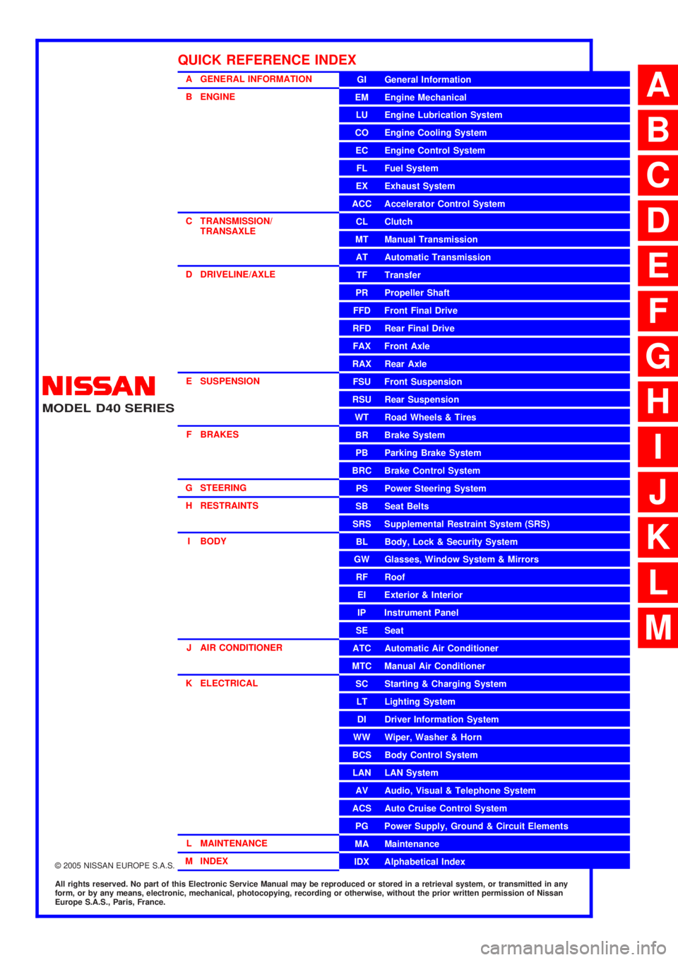
A GENERAL INFORMATION
B ENGINE
C TRANSMISSION/TRANSAXLE
D DRIVELINE/AXLE
E SUSPENSION F BRAKES
G STEERING H RESTRAINTS
I BODY
J AIR CONDITIONER
K ELECTRICAL
L MAINTENANCE
M INDEXGI General Information
EM Engine Mechanical
LU Engine Lubrication System
CO Engine Cooling System
EC Engine Control System
FL Fuel System
EX Exhaust System
ACC Accelerator Control System
CL Clutch
MTManualTransmission
AT Automatic Transmission
TF Transfer
PR Propeller Shaft
FFD Front Final Drive
RFD Rear Final Drive
FAX Front Axle
RAX Rear Axle
FSU Front Suspension
RSU Rear Suspension
WT Road Wheels & Tires
BR Brake System
PB Parking Brake System
BRC Brake Control System
PS Power Steering System
SB Seat Belts
SRS Supplemental Restraint System (SRS)
BL Body, Lock & Security System
GW Glasses, Window System & Mirrors
RF Roof
EI Exterior & Interior
IP Instrument Panel
SE Seat
ATC Automatic Air Conditioner
MTC Manual Air Conditioner
SC Starting & Charging System
LT Lighting System
DI Driver Information System
WW Wiper, Washer & Horn
BCS Body Control System
LAN LAN System
AV Audio, Visual & Telephone System
ACS Auto Cruise Control System
PG Power Supply, Ground & Circuit Elements
MA Maintenance
IDX Alphabetical Index
QUICK REFERENCE INDEX
A
B
C
D
E
F
G
H
I
J
K
L
M
Page 2 of 3171

FOREWORD
This manual contains maintenance and repair procedures for the NISSAN
NAVARA,modelD40 series.
In order to assure your safety and the efficient functioning of the vehicle,
this manual should be read thoroughly. It is especially important that the
PRECAUTIONS in the GI section be completely understood before starting
any repair task.
All information in this manual is based on the latest product information
at the time of publication. The right is reserved to make changes in speci-
fications and methods at any time without notice.
IMPORTANT SAFETY NOTICE
The proper performance of service is essential for both the safety of the
technician and the efficient functioning of the vehicle.
The service methods in this Service Manual are described in such a man-
ner that the service may be performed safely and accurately.
Service varies with the procedures used, the skills of the technician and the
tools and parts available. Accordingly, anyone using service procedures,
tools or parts which are not specifically recommended by NISSAN must
first be completely satisfied that neither personal safety nor the vehicle's
safety will be jeopardized by the service method selected.
NISSAN EUROPE S.A.S.
Service Engineering SectionParis, France
Page 9 of 3171
AT-1
AUTOMATIC TRANSMISSION
C TRANSMISSION/TRANSAXLE
CONTENTS
D
E
F
G
H
I
J
K
L
M
SECTIONAT
A
B
AT
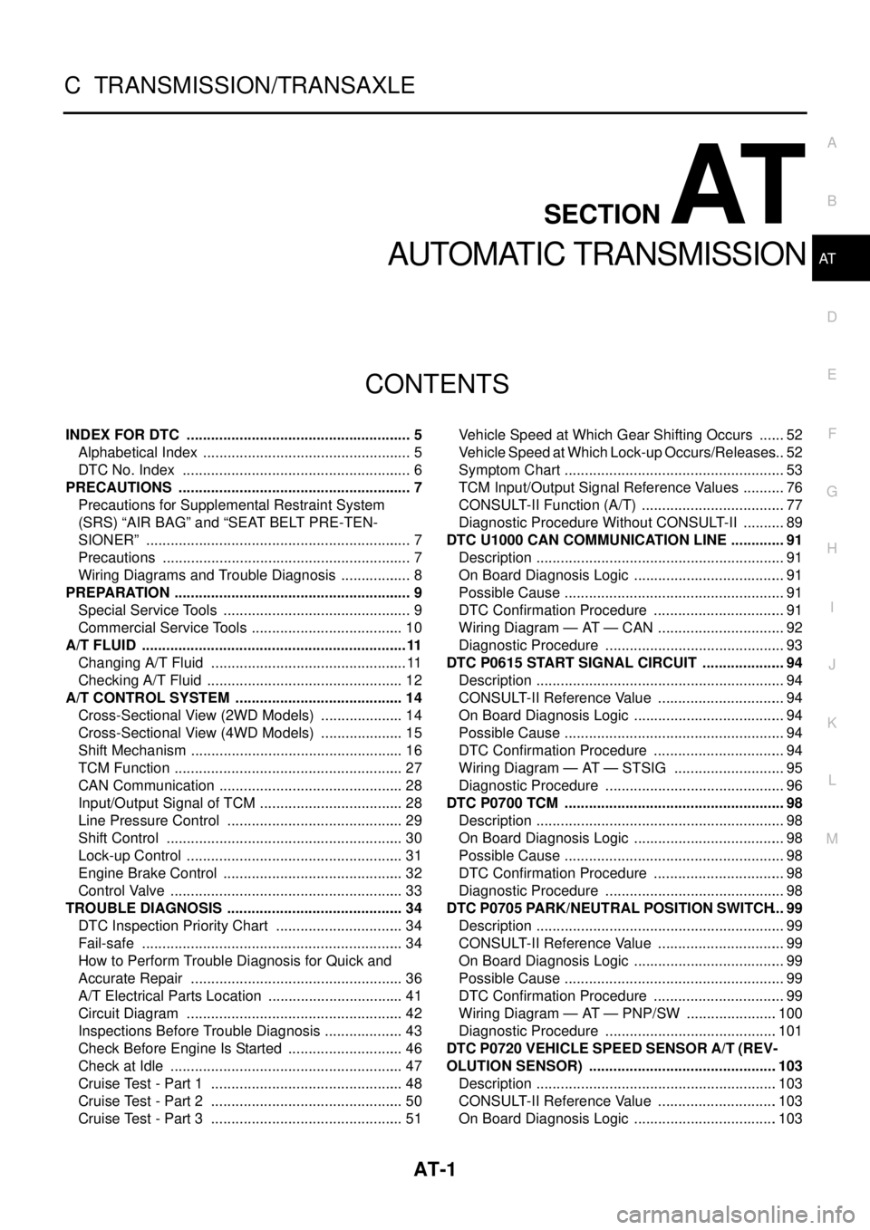
AUTOMATIC TRANSMISSION
INDEX FOR DTC ........................................................ 5
Alphabetical Index .................................................... 5
DTC No. Index ......................................................... 6
PRECAUTIONS .......................................................... 7
Precautions for Supplemental Restraint System
(SRS)“AIRBAG”and“SEATBELTPRE-TEN-
SIONER” .................................................................. 7
Precautions .............................................................. 7
Wiring Diagrams and Trouble Diagnosis .................. 8
PREPARATION ........................................................... 9
Special Service Tools ............................................... 9
Commercial Service Tools ...................................... 10
A/T FLUID ..................................................................11
Changing A/T Fluid ................................................. 11
Checking A/T Fluid ................................................. 12
A/T CONTROL SYSTEM .......................................... 14
Cross-Sectional View (2WD Models) ..................... 14
Cross-Sectional View (4WD Models) ..................... 15
Shift Mechanism ..................................................... 16
TCM Function ......................................................... 27
CAN Communication .............................................. 28
Input/Output Signal of TCM .................................... 28
Line Pressure Control ............................................ 29
Shift Control ........................................................... 30
Lock-up Control ...................................................... 31
Engine Brake Control ............................................. 32
Control Valve .......................................................... 33
TROUBLE DIAGNOSIS ............................................ 34
DTC Inspection Priority Chart ................................ 34
Fail-safe ................................................................. 34
How to Perform Trouble Diagnosis for Quick and
Accurate Repair ..................................................... 36
A/T Electrical Parts Location .................................. 41
Circuit Diagram ...................................................... 42
Inspections Before Trouble Diagnosis .................... 43
Check Before Engine Is Started ............................. 46
Check at Idle .......................................................... 47
Cruise Test - Part 1 ................................................ 48
Cruise Test - Part 2 ................................................ 50
Cruise Test - Part 3 ................................................ 51Vehicle Speed at Which Gear Shifting Occurs ....... 52
Vehicle Speed at Which Lock-up Occurs/Releases... 52
Symptom Chart ....................................................... 53
TCM Input/Output Signal Reference Values ........... 76
CONSULT-II Function (A/T) .................................... 77
Diagnostic Procedure Without CONSULT-II ........... 89
DTC U1000 CAN COMMUNICATION LINE .............. 91
Description .............................................................. 91
On Board Diagnosis Logic ...................................... 91
Possible Cause ....................................................... 91
DTC Confirmation Procedure ................................. 91
Wiring Diagram — AT — CAN ................................ 92
Diagnostic Procedure ............................................. 93
DTC P0615 START SIGNAL CIRCUIT ..................... 94
Description .............................................................. 94
CONSULT-II Reference Value ................................ 94
On Board Diagnosis Logic ...................................... 94
Possible Cause ....................................................... 94
DTC Confirmation Procedure ................................. 94
Wiring Diagram — AT — STSIG ............................ 95
Diagnostic Procedure ............................................. 96
DTC P0700 TCM ....................................................... 98
Description .............................................................. 98
On Board Diagnosis Logic ...................................... 98
Possible Cause ....................................................... 98
DTC Confirmation Procedure ................................. 98
Diagnostic Procedure ............................................. 98
DTC P0705 PARK/NEUTRAL POSITION SWITCH... 99
Description .............................................................. 99
CONSULT-II Reference Value ................................ 99
On Board Diagnosis Logic ...................................... 99
Possible Cause ....................................................... 99
DTC Confirmation Procedure ................................. 99
Wiring Diagram — AT — PNP/SW .......................100
Diagnostic Procedure ...........................................101
DTC P0720 VEHICLE SPEED SENSOR A/T (REV-
OLUTION SENSOR) ...............................................103
Description ............................................................103
CONSULT-II Reference Value ..............................103
On Board Diagnosis Logic ....................................103
Page 11 of 3171

AT-3
D
E
F
G
H
I
J
K
L
MA
B
AT CONSULT-II Reference Value .............................. 144
On Board Diagnosis Logic ................................... 144
Possible Cause .................................................... 144
DTC Confirmation Procedure ............................... 144
Diagnostic Procedure ........................................... 145
DTC P1767 HIGH AND LOW REVERSE CLUTCH
SOLENOID VALVE ................................................. 147
Description ........................................................... 147
CONSULT-II Reference Value .............................. 147
On Board Diagnosis Logic ................................... 147
Possible Cause .................................................... 147
DTC Confirmation Procedure ............................... 147
Diagnostic Procedure ........................................... 148
DTC P1769 HIGH AND LOW REVERSE CLUTCH
SOLENOID VALVE FUNCTION ............................. 149
Description ........................................................... 149
CONSULT-II Reference Value .............................. 149
On Board Diagnosis Logic ................................... 149
Possible Cause .................................................... 149
DTC Confirmation Procedure ............................... 149
Diagnostic Procedure ........................................... 150
DTC P1772 LOW COAST BRAKE SOLENOID
VALVE ..................................................................... 152
Description ........................................................... 152
CONSULT-II Reference Value .............................. 152
On Board Diagnosis Logic ................................... 152
Possible Cause .................................................... 152
DTC Confirmation Procedure ............................... 152
Diagnostic Procedure ........................................... 153
DTC P1774 LOW COAST BRAKE SOLENOID
VALVE FUNCTION ................................................. 154
Description ........................................................... 154
CONSULT-II Reference Value .............................. 154
On Board Diagnosis Logic ................................... 154
Possible Cause .................................................... 154
DTC Confirmation Procedure ............................... 154
Diagnostic Procedure ........................................... 155
DTC P1841 ATF PRESSURE SWITCH 1 ............... 156
Description ........................................................... 156
CONSULT-II Reference Value .............................. 156
On Board Diagnosis Logic ................................... 156
Possible Cause .................................................... 156
DTC Confirmation Procedure ............................... 156
Diagnostic Procedure ........................................... 157
DTC P1843 ATF PRESSURE SWITCH 3 ............... 158
Description ........................................................... 158
CONSULT-II Reference Value .............................. 158
On Board Diagnosis Logic ................................... 158
Possible Cause .................................................... 158
DTC Confirmation Procedure ............................... 158
Diagnostic Procedure ........................................... 159
DTC P1845 ATF PRESSURE SWITCH 5 ............... 160
Description ........................................................... 160
CONSULT-II Reference Value .............................. 160
On Board Diagnosis Logic ................................... 160
Possible Cause .................................................... 160
DTC Confirmation Procedure ............................... 160
Diagnostic Procedure ........................................... 161
DTC P1846 ATF PRESSURE SWITCH 6 ............... 162Description ............................................................162
CONSULT-II Reference Value ..............................162
On Board Diagnosis Logic ....................................162
Possible Cause .....................................................162
DTC Confirmation Procedure ...............................162
Diagnostic Procedure ...........................................163
MAIN POWER SUPPLY AND GROUND CIRCUIT. 164
Wiring Diagram — AT — MAIN ............................164
Diagnostic Procedure ...........................................165
CLOSED THROTTLE POSITION AND WIDE OPEN
THROTTLE POSITION CIRCUIT ............................168
CONSULT-II Reference Value ..............................168
Diagnostic Procedure ...........................................168
BRAKE SIGNAL CIRCUIT ......................................169
CONSULT-II Reference Value ..............................169
Diagnostic Procedure ...........................................169
1ST POSITION SWITCH .........................................170
CONSULT-II Reference Value ..............................170
Diagnostic Procedure ...........................................170
OVERDRIVE CONTROL SWITCH .........................172
CONSULT-II Reference Value ..............................172
Diagnostic Procedure ...........................................172
TROUBLE DIAGNOSIS FOR SYMPTOMS ............174
Wiring Diagram — AT — NONDTC ......................174
OD OFF Indicator Lamp Does Not Come On .......177
Engine Cannot Be Started in “P” or “N” Position ..177
In “P” Position, Vehicle Moves When Pushed ......178
In “N” Position, Vehicle Moves ..............................179
Large Shock (“N” to “D” Position) .........................180
Vehicle Does Not Creep Backward in “R” Position. 182
Vehicle Does Not Creep Forward in “D” Position . 184
Vehicle Cannot Be Started from D
1......................186
A/T Does Not Shift: D
1®D2................................188
A/T Does Not Shift: D
2®D3................................190
A/T Does Not Shift: D
3®D4................................192
A/T Does Not Shift: D
4®D5................................194
A/T Does Not Perform Lock-up ............................196
A/T Does Not Hold Lock-up Condition ..................197
Lock-up Is Not Released ......................................199
Engine Speed Does Not Return to Idle ................199
A/T Does Not Shift: 5th Gear®4th Gear ............200
A/T Does Not Shift: 4th Gear®3rd Gear ............202
A/T Does Not Shift: 3rd Gear®2nd Gear ...........203
A/T Does Not Shift: 2nd Gear®1st Gear ...........204
Vehicle Does Not Decelerate by Engine Brake ....206
SHIFT CONTROL SYSTEM ....................................208
Control Device Removal and Installation ..............208
Control Cable Removal and Installation ...............210
Adjustment of A/T Position ...................................211
Checking of A/T Position ......................................211
A/T SHIFT LOCK SYSTEM ....................................212
Description ............................................................212
Shift Lock System Electrical Parts Location .........212
Wiring Diagram — A/T — SHIFT ..........................213
Diagnostic Procedure ...........................................214
KEY INTERLOCK CABLE ......................................216
Removal and Installation ......................................216
ON-VEHICLE SERVICE ..........................................218
Control Valve With TCM and A/T Fluid Temperature
Page 12 of 3171

AT-4
Sensor 2 ...............................................................218
Parking Components (2WD Models Only) ............230
Rear Oil Seal ........................................................237
Revolution Sensor Components (2WD Models
Only) .....................................................................238
AIR BREATHER HOSE ...........................................243
Removal and Installation ......................................243
A/T FLUID COOLER ...............................................244
Removal and Installation ......................................244
TRANSMISSION ASSEMBLY ................................247
Removal and Installation ......................................247
OVERHAUL .............................................................251
Components .........................................................251
Oil Channel ...........................................................259
Locations of Adjusting Shims, Needle Bearings,
Thrust Washers and Snap Rings ..........................261
DISASSEMBLY .......................................................263
Disassembly .........................................................263
REPAIR FOR COMPONENT PARTS ......................281
Oil Pump ...............................................................281
Front Sun Gear, 3rd One-way Clutch ...................284Front Carrier, Input Clutch, Rear Internal Gear .....286
Mid Sun Gear, Rear Sun Gear, High and Low
Reverse Clutch Hub ..............................................291
High and Low Reverse Clutch ..............................296
Direct Clutch .........................................................298
ASSEMBLY .............................................................300
Assembly (1) .........................................................300
Adjustment ............................................................313
Assembly (2) .........................................................316
SERVICE DATA AND SPECIFICATIONS (SDS) ....323
General Specifications ..........................................323
Stall Speed ............................................................323
Line Pressure ........................................................323
Vehicle Speed at Which Gear Shifting Occurs ......324
Vehicle Speed at Which Lock-Up Occurs/Releases.324
A/T Fluid Temperature Sensor ..............................324
Vehicle Speed Sensor A/T (Revolution Sensor) ...325
Turbine Revolution Sensor ....................................325
Reverse Brake ......................................................325
Total End Play .......................................................325
Page 15 of 3171
PRECAUTIONS
AT-7
D
E
F
G
H
I
J
K
L
MA
B
AT
PRECAUTIONSPFP:00001
Precautions for Supplemental Restraint System (SRS) “AIR BAG” and “SEAT
BELT PRE-TENSIONER”
ECS00IPT
The Supplemental Restraint System such as “AIR BAG” and “SEAT BELT PRE-TENSIONER”, used along
with a front seat belt, helps to reduce the risk or severity of injury to the driver and front passenger for certain
types of collision. Information necessary to service the system safely is included in the SRS and SB section of
this Service Manual.
WARNING:
lTo avoid rendering the SRS inoperative, which could increase the risk of personal injury or death
in the event of a collision which would result in air bag inflation, all maintenance must be per-
formed by an authorized NISSAN/INFINITI dealer.
lImproper maintenance, including incorrect removal and installation of the SRS, can lead to per-
sonal injury caused by unintentional activation of the system. For removal of Spiral Cable and Air
Bag Module, see the SRS section.
lDo not use electrical test equipment on any circuit related to the SRS unless instructed to in this
Service Manual. SRS wiring harnesses can be identified by yellow and/or orange harnesses or
harness connectors.
PrecautionsECS00IPR
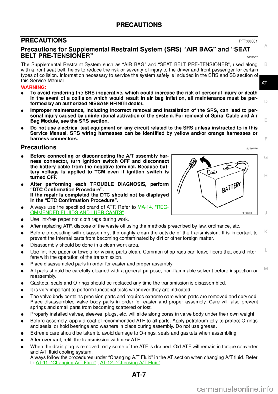
lBefore connecting or disconnecting the A/T assembly har-
ness connector, turn ignition switch OFF and disconnect
the battery cable from the negative terminal. Because bat-
tery voltage is applied to TCM even if ignition switch is
turned OFF.
lAfter performing each TROUBLE DIAGNOSIS, perform
“DTC Confirmation Procedure”.
If the repair is completed the DTC should not be displayed
in the “DTC Confirmation Procedure”.
lAlways use the specified brand of ATF. Refer toMA-14, "REC-
OMMENDED FLUIDS AND LUBRICANTS".
lUse lint-free paper not cloth rags during work.
lAfter replacing ATF, dispose of the waste oil using the methods prescribed by law, ordinance, etc.
lBefore proceeding with disassembly, thoroughly clean the outside of the transmission. It is important to
prevent the internal parts from becoming contaminated by dirt or other foreign matter.
lDisassembly should be done in a clean work area.
lUse lint-free paper or towels for wiping parts clean. Common shop rags can leave fibers that could inter-
fere with the operation of the transmission.
lPlace disassembled parts in order for easier and proper assembly.
lAll parts should be carefully cleaned with a general purpose, non-flammable solvent before inspection or
reassembly.
lGaskets, seals and O-rings should be replaced any time the transmission is disassembled.
lIt is very important to perform functional tests whenever they are indicated.
lThe valve body contains precision parts and requires extreme care when parts are removed and serviced.
Place disassembled valve body parts in order for easier and proper assembly. Care will also prevent
springs and small parts from becoming scattered or lost.
lProperly installed valves, sleeves, plugs, etc. will slide along bores in valve body under their own weight.
lBefore assembly, apply a coat of recommended ATF to all parts. Apply petroleum jelly to protect O-rings
and seals, or hold bearings and washers in place during assembly. Do not use grease.
lExtreme care should be taken to avoid damage to O-rings, seals and gaskets when assembling.
lAfter overhaul, refill the transmission with new ATF.
lWhen the drain plug is removed, only some of the ATF is drained. Old ATF will remain in torque converter
and A/T fluid cooling system.
Always follow the procedures under “Changing A/T Fluid” in the AT section when changing A/T fluid. Refer
toAT-11, "
Changing A/T Fluid",AT-12, "Checking A/T Fluid".
SEF289H
Page 17 of 3171
PREPARATION
AT-9
D
E
F
G
H
I
J
K
L
MA
B
AT
PREPARATIONPFP:00002
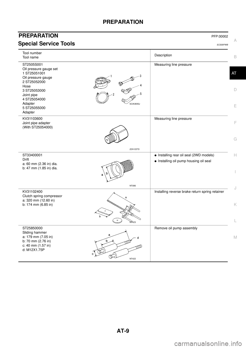
Special Service ToolsECS00FWB
Tool number
Tool nameDescription
ST2505S001
Oil pressure gauge set
1 ST25051001
Oil pressure gauge
2 ST25052000
Hose
3 ST25053000
Joint pipe
4 ST25054000
Adapter
5 ST25055000
AdapterMeasuring line pressure
KV31103600
Joint pipe adapter
(With ST25054000)Measuring line pressure
ST33400001
Drift
a: 60 mm (2.36 in) dia.
b: 47 mm (1.85 in) dia.
lInstalling rear oil seal (2WD models)
lInstalling oil pump housing oil seal
KV31102400
Clutch spring compressor
a: 320 mm (12.60 in)
b: 174 mm (6.85 in)Installing reverse brake return spring retainer
ST25850000
Sliding hammer
a: 179 mm (7.05 in)
b: 70 mm (2.76 in)
c: 40 mm (1.57 in)
d: M12X1.75PRemove oil pump assembly
SCIA3695J
ZZA1227D
NT086
NT423
NT422
Page 18 of 3171
AT-10
PREPARATION
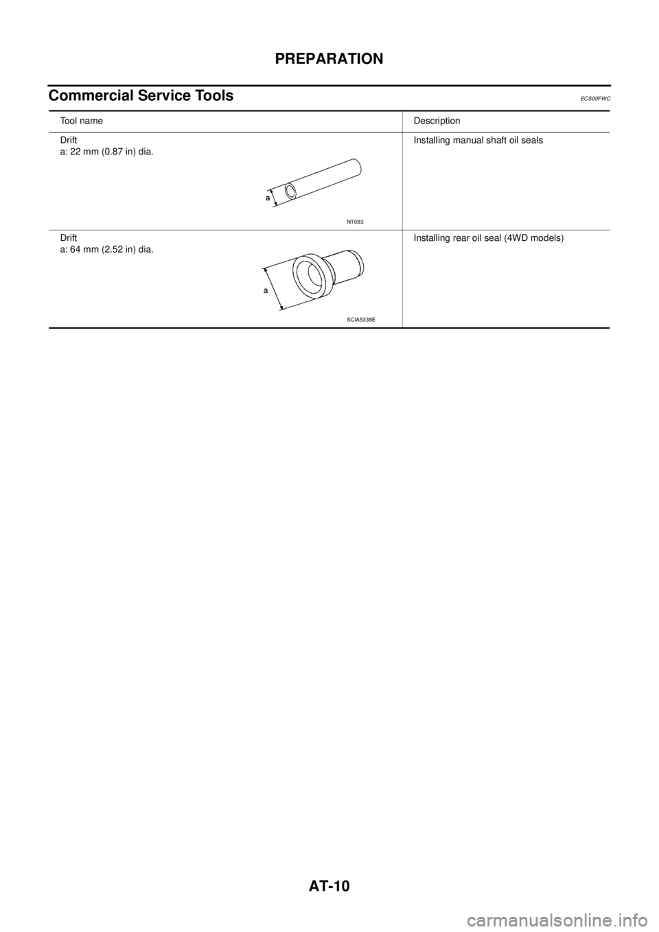
Commercial Service Tools
ECS00FWC
Tool nameDescription
Drift
a: 22 mm (0.87 in) dia.Installing manual shaft oil seals
Drift
a: 64 mm (2.52 in) dia.Installing rear oil seal (4WD models)
NT083
SCIA5338E