Page 2297 of 3171
MA-22
ENGINE MAINTENANCE
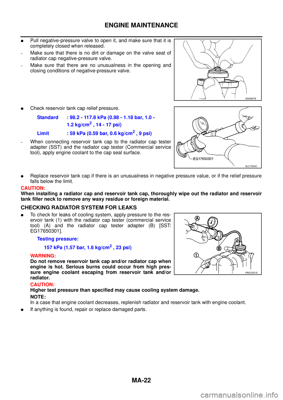
lPull negative-pressure valve to open it, and make sure that it is
completely closed when released.
–Makesurethatthereisnodirtordamageonthevalveseatof
radiator cap negative-pressure valve.
–Make sure that there are no unusualness in the opening and
closing conditions of negative-pressure valve.
lCheck reservoir tank cap relief pressure.
–When connecting reservoir tank cap to the radiator cap tester
adapter (SST) and the radiator cap tester (Commercial service
tool), apply engine coolant to the cap seal surface.
lReplace reservoir tank cap if there is an unusualness in negative pressure value, or if the relief pressure
falls below the limit.
CAUTION:
When installing a radiator cap and reservoir tank cap, thoroughly wipe out the radiator and reservoir
tank filler neck to remove any waxy residue or foreign material.
CHECKING RADIATOR SYSTEM FOR LEAKS
lTo check for leaks of cooling system, apply pressure to the res-
ervoir tank (1) with the radiator cap tester (commercial service
tool) (A) and the radiator cap tester adapter (B) [SST:
EG17650301].
WARNING:
Do not remove reservoir tank cap and/or radiator cap when
engine is hot. Serious burns could occur from high pres-
sure engine coolant escaping from reservoir tank and/or
radiator.
CAUTION:
Higher test pressure than specified may cause cooling system damage.
NOTE:
In a case that engine coolant decreases, replenish radiator and reservoir tank with engine coolant.
lIf anything is found, repair or replace damaged parts.
SMA967B
Standard : 98.2 - 117.8 kPa (0.98 - 1.18 bar, 1.0 -
1.2 kg/cm
2,14-17psi)
Limit : 59 kPa (0.59 bar, 0.6 kg/cm
2,9psi)
SLC755AC
Testing pressure:
157 kPa (1.57 bar, 1.6 kg/cm
2,23psi)
PBIC3501E
Page 2299 of 3171
MA-24
ENGINE MAINTENANCE
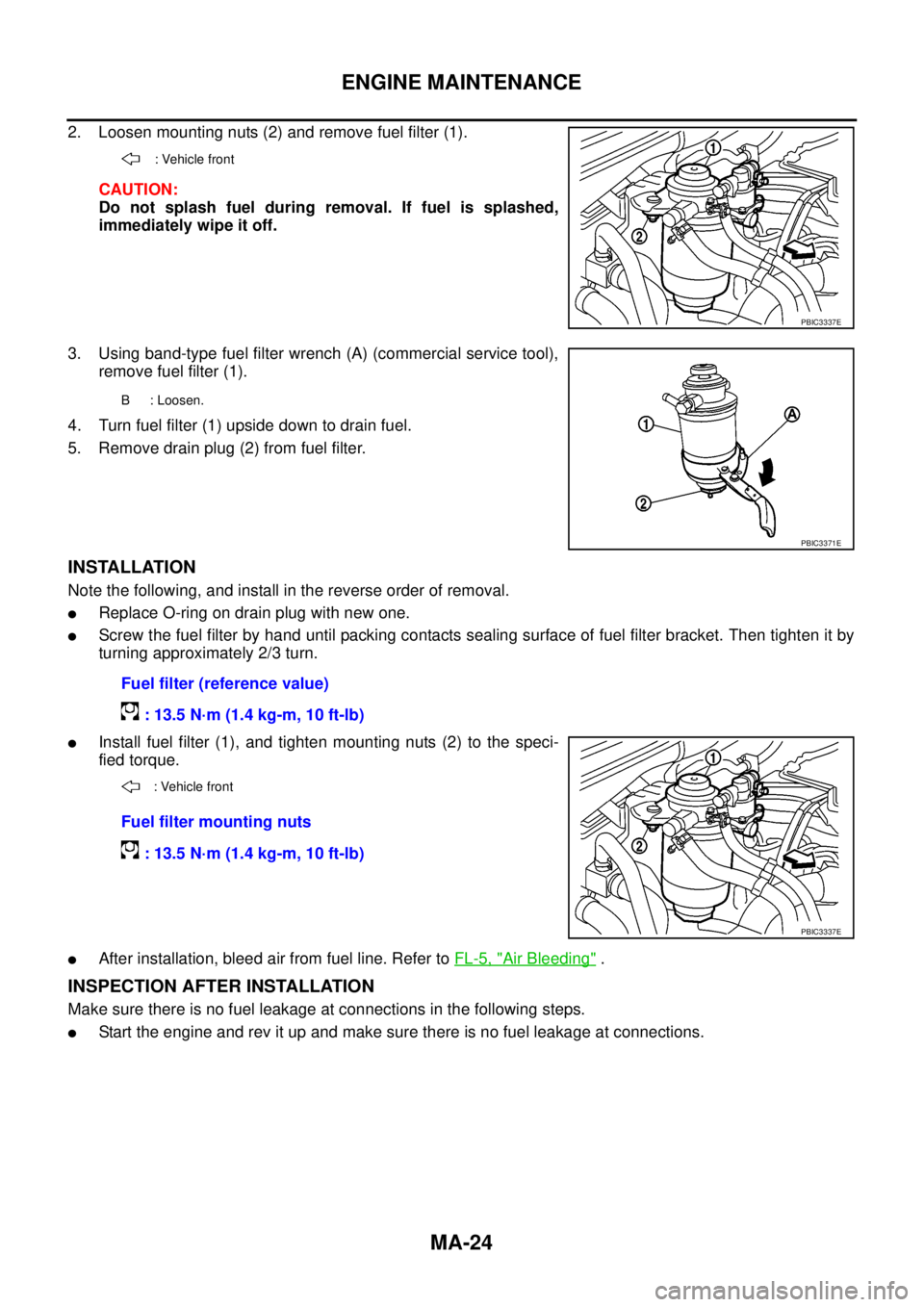
2. Loosen mounting nuts (2) and remove fuel filter (1).
CAUTION:
Do not splash fuel during removal. If fuel is splashed,
immediately wipe it off.
3. Using band-type fuel filter wrench (A) (commercial service tool),
remove fuel filter (1).
4. Turn fuel filter (1) upside down to drain fuel.
5. Remove drain plug (2) from fuel filter.
INSTALLATION
Note the following, and install in the reverse order of removal.
lReplace O-ring on drain plug with new one.
lScrew the fuel filter by hand until packing contacts sealing surface of fuel filter bracket. Then tighten it by
turning approximately 2/3 turn.
lInstall fuel filter (1), and tighten mounting nuts (2) to the speci-
fied torque.
lAfter installation, bleed air from fuel line. Refer toFL-5, "Air Bleeding".
INSPECTION AFTER INSTALLATION
Make sure there is no fuel leakage at connections in the following steps.
lStart the engine and rev it up and make sure there is no fuel leakage at connections.
: Vehicle front
PBIC3337E
B : Loosen.
PBIC3371E
Fuel filter (reference value)
: 13.5 N·m (1.4 kg-m, 10 ft-lb)
: Vehicle front
Fuel filter mounting nuts
: 13.5 N·m (1.4 kg-m, 10 ft-lb)
PBIC3337E
Page 2309 of 3171
MA-34
CHASSIS AND BODY MAINTENANCE
Changing Rear Final Drive Oil (Rear Differential Gear Oil)
ELS001IW
CAUTION:
If using the vehicle for towing, the final drive oil must be replaced as specified. Refer toMA-8, "
PERI-
ODIC MAINTENANCE".
DRAINING
1. Stop the engine.
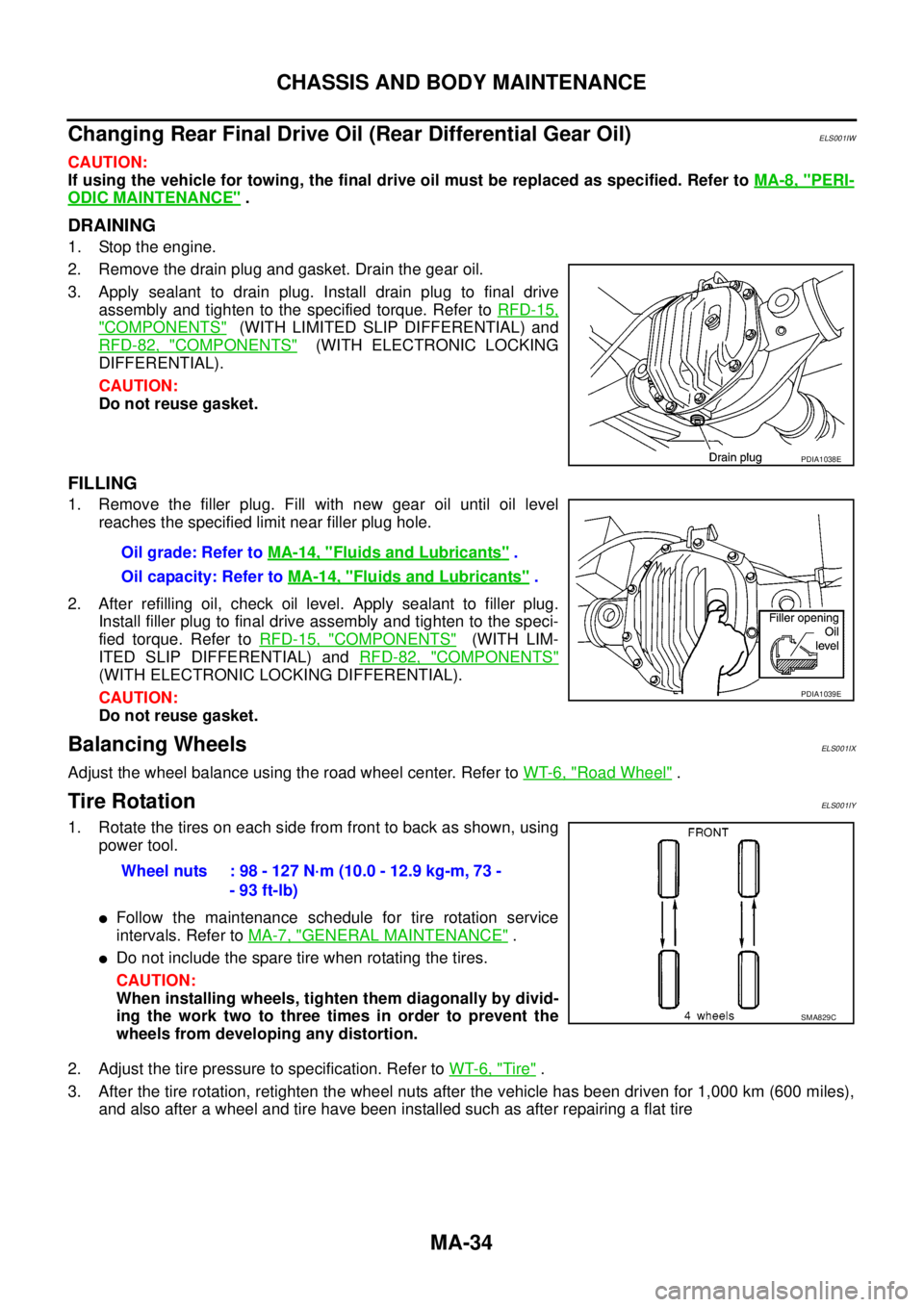
2. Remove the drain plug and gasket. Drain the gear oil.
3. Apply sealant to drain plug. Install drain plug to final drive
assembly and tighten to the specified torque. Refer toRFD-15,
"COMPONENTS"(WITH LIMITED SLIP DIFFERENTIAL) and
RFD-82, "
COMPONENTS"(WITH ELECTRONIC LOCKING
DIFFERENTIAL).
CAUTION:
Do not reuse gasket.
FILLING
1. Remove the filler plug. Fill with new gear oil until oil level
reaches the specified limit near filler plug hole.
2. After refilling oil, check oil level. Apply sealant to filler plug.
Install filler plug to final drive assembly and tighten to the speci-
fied torque. Refer toRFD-15, "
COMPONENTS"(WITH LIM-
ITED SLIP DIFFERENTIAL) andRFD-82, "
COMPONENTS"
(WITH ELECTRONIC LOCKING DIFFERENTIAL).
CAUTION:
Do not reuse gasket.
Balancing WheelsELS001IX
Adjust the wheel balance using the road wheel center. Refer toWT-6, "Road Wheel".
Tire RotationELS001IY
1. Rotate the tires on each side from front to back as shown, using
power tool.
lFollow the maintenance schedule for tire rotation service
intervals. Refer toMA-7, "
GENERAL MAINTENANCE".
lDo not include the spare tire when rotating the tires.
CAUTION:
When installing wheels, tighten them diagonally by divid-
ing the work two to three times in order to prevent the
wheels from developing any distortion.
2. Adjust the tire pressure to specification. Refer toWT-6, "
Tire".
3. After the tire rotation, retighten the wheel nuts after the vehicle has been driven for 1,000 km (600 miles),
and also after a wheel and tire have been installed such as after repairing a flat tire
PDIA1038E
Oil grade: Refer toMA-14, "Fluids and Lubricants".
Oil capacity: Refer toMA-14, "
Fluids and Lubricants".
PDIA1039E
Wheel nuts : 98 - 127 N·m (10.0 - 12.9 kg-m, 73 -
- 93 ft-lb)
SMA829C
Page 2316 of 3171
SERVICE DATA AND SPECIFICATIONS (SDS)
MA-41
C
D
E
F
G
H
I
J
K
MA
B
MA
SERVICE DATA AND SPECIFICATIONS (SDS)PFP:00030
Standard and LimitELS001J8
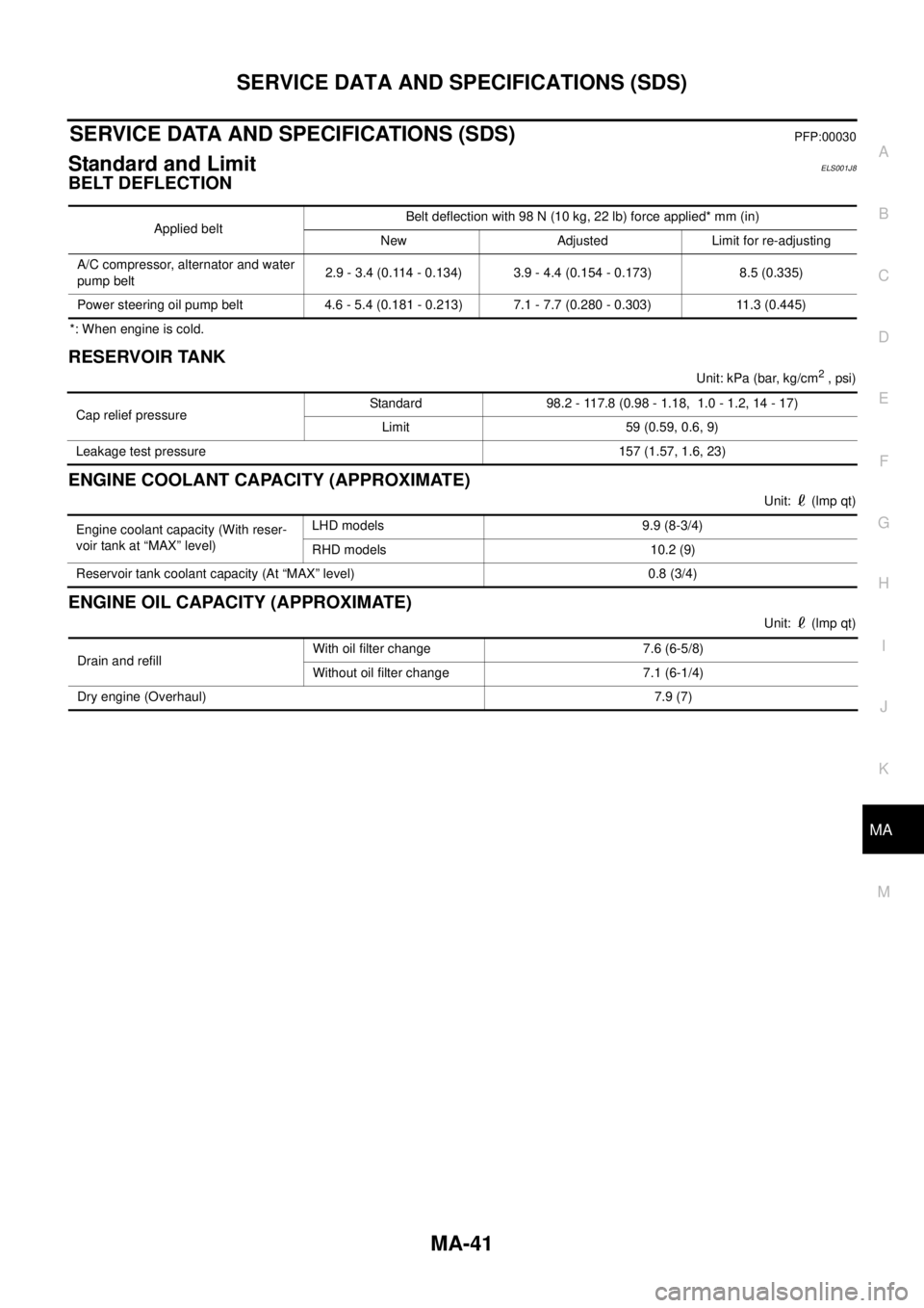
BELT DEFLECTION
*: When engine is cold.
RESERVOIR TANK
Unit:kPa(bar,kg/cm2, psi)
ENGINE COOLANT CAPACITY (APPROXIMATE)
Unit: (lmp qt)
ENGINE OIL CAPACITY (APPROXIMATE)
Unit: (lmp qt) Applied beltBelt deflection with 98 N (10 kg, 22 lb) force applied* mm (in)
New Adjusted Limit for re-adjusting
A/C compressor, alternator and water
pump belt2.9 - 3.4 (0.114 - 0.134) 3.9 - 4.4 (0.154 - 0.173) 8.5 (0.335)
Power steering oil pump belt 4.6 - 5.4 (0.181 - 0.213) 7.1 - 7.7 (0.280 - 0.303) 11.3 (0.445)
Cap relief pressureStandard 98.2 - 117.8 (0.98 - 1.18, 1.0 - 1.2, 14 - 17)
Limit 59 (0.59, 0.6, 9)
Leakage test pressure 157 (1.57, 1.6, 23)
Engine coolant capacity (With reser-
voir tank at “MAX” level)LHD models 9.9 (8-3/4)
RHD models 10.2 (9)
Reservoir tank coolant capacity (At “MAX” level) 0.8 (3/4)
Drain and refillWith oil filter change 7.6 (6-5/8)
Without oil filter change 7.1 (6-1/4)
Dry engine (Overhaul)7.9 (7)
Page 2317 of 3171
MA-42
SERVICE DATA AND SPECIFICATIONS (SDS)
Page 2318 of 3171
MT-1
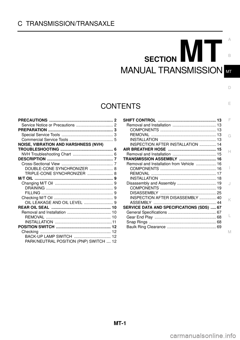
MANUAL TRANSMISSION
C TRANSMISSION/TRANSAXLE
CONTENTS
D
E
F
G
H
I
J
K
L
M
SECTIONMT
A
B
MT
MANUAL TRANSMISSION
PRECAUTIONS .......................................................... 2
Service Notice or Precautions .................................. 2
PREPARATION ........................................................... 3
Special Service Tools ............................................... 3
Commercial Service Tools ........................................ 5
NOISE, VIBRATION AND HARSHNESS (NVH)
TROUBLESHOOTING ................................................ 6
NVH Troubleshooting Chart ..................................... 6
DESCRIPTION ............................................................ 7
Cross-Sectional View ............................................... 7
DOUBLE-CONE SYNCHRONIZER ...................... 8
TRIPLE-CONE SYNCHRONIZER ........................ 8
M/T OIL ....................................................................... 9
Changing M/T Oil ..................................................... 9
DRAINING ............................................................. 9
FILLING ................................................................. 9
Checking M/T Oil ...................................................... 9
OIL LEAKAGE AND OIL LEVEL ........................... 9
REAR OIL SEAL ...................................................... 10
Removal and Installation ........................................ 10
REMOVAL ........................................................... 10
INSTALLATION .................................................... 11
POSITION SWITCH .................................................. 12
Checking ................................................................ 12
BACK-UP LAMP SWITCH .................................. 12
PARK/NEUTRAL POSITION (PNP) SWITCH ..... 12SHIFT CONTROL ..................................................... 13
Removal and Installation ........................................ 13
COMPONENTS ................................................... 13
REMOVAL ........................................................... 13
INSTALLATION ................................................... 13
INSPECTION AFTER INSTALLATION ................ 14
AIR BREATHER HOSE ............................................ 15
Removal and Installation ........................................ 15
TRANSMISSION ASSEMBLY .................................. 16
Removal and Installation from Vehicle ................... 16
COMPONENTS ................................................... 16
REMOVAL ........................................................... 17
INSTALLATION ................................................... 18
Disassembly and Assembly .................................... 19
COMPONENTS ................................................... 19
DISASSEMBLY ................................................... 25
INSPECTION AFTER DISASSEMBLY ................ 40
ASSEMBLY ......................................................... 44
SERVICE DATA AND SPECIFICATIONS (SDS) ...... 67
General Specifications ............................................ 67
Gear End Play ........................................................ 68
Snap Rings ............................................................. 68
Baulk Ring Clearance ............................................. 69
Page 2319 of 3171
MT-2
PRECAUTIONS
PRECAUTIONS
PFP:00001
ServiceNoticeorPrecautionsECS00ICY
lDo not reuse transmission oil, once it has been drained.
lCheck oil level or replace oil with vehicle on level surface.
lDuring removal or installation, keep inside of transmission clear of dust or dirt.
lCheck for the correct installation status prior to removal or disassembly. If matching mark are required, be
certain they do not interfere with the function of the parts they are applied.
lIn principle, tighten bolts or nuts gradually in several steps working diagonally from inside to outside. If
tightening sequence is specified, use it.
lBe careful not to damage sliding surfaces and mating surfaces.
Page 2320 of 3171
PREPARATION
MT-3
D
E
F
G
H
I
J
K
L
MA
B
MT
PREPARATIONPFP:00002
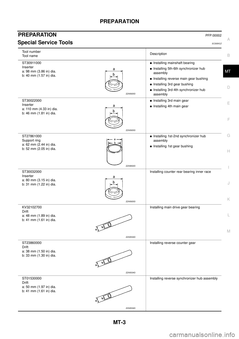
Special Service ToolsECS00ICZ
Tool number
Tool nameDescription
ST30911000
Inserter
a: 98 mm (3.86 in) dia.
b: 40 mm (1.57 in) dia.
lInstalling mainshaft bearing
lInstalling 5th-6th synchronizer hub
assembly
lInstalling reverse main gear bushing
lInstalling 3rd gear bushing
lInstalling 3rd-4th synchronizer hub
assembly
ST30022000
Inserter
a: 110 mm (4.33 in) dia.
b: 46 mm (1.81 in) dia.
lInstalling 3rd main gear
lInstalling 4th main gear
ST27861000
Support ring
a: 62 mm (2.44 in) dia.
b: 52 mm (2.05 in) dia.
lInstalling 1st-2nd synchronizer hub
assembly
lInstalling 1st gear bushing
ST30032000
Inserter
a: 80 mm (3.15 in) dia.
b: 31 mm (1.22 in) dia.Installing counter rear bearing inner race
KV32102700
Drift
a: 48 mm (1.89 in) dia.
b: 41 mm (1.61 in) dia.Installing main drive gear bearing
ST23860000
Drift
a: 38 mm (1.50 in) dia.
b: 33 mm (1.30 in) dia.Installing reverse counter gear
ST01530000
Drift
a: 50 mm (1.97 in) dia.
b: 41 mm (1.61 in) dia.Installing reverse synchronizer hub assembly
ZZA0920D
ZZA0920D
ZZA0832D
ZZA0920D
ZZA0534D
ZZA0534D
ZZA0534D