2005 NISSAN NAVARA service
[x] Cancel search: servicePage 2836 of 3171
PRECAUTIONS
SC-3
C
D
E
F
G
H
I
J
L
MA
B
SC
PRECAUTIONSPFP:00011
Precautions for Supplemental Restraint System (SRS) “AIR BAG” and “SEAT
BELT PRE-TENSIONER”
EKS00MZ4
The Supplemental Restraint System such as “AIR BAG” and “SEAT BELT PRE-TENSIONER”, used along
with a front seat belt, helps to reduce the risk or severity of injury to the driver and front passenger for certain
types of collision. Information necessary to service the system safely is included in the SRS and SB section of
this Service Manual.
WARNING:
lTo avoid rendering the SRS inoperative, which could increase the risk of personal injury or death
in the event of a collision which would result in air bag inflation, all maintenance must be per-
formed by an authorized NISSAN/INFINITI dealer.
lImproper maintenance, including incorrect removal and installation of the SRS, can lead to per-
sonal injury caused by unintentional activation of the system. For removal of Spiral Cable and Air
Bag Module, see the SRS section.
lDo not use electrical test equipment on any circuit related to the SRS unless instructed to in this
Service Manual. SRS wiring harnesses can be identified by yellow and/or orange harnesses or
harness connectors.
Wiring Diagrams and Trouble DiagnosisEKS00MZ5
When you read wiring diagrams, refer to the followings:
lGI-15, "How to Read Wiring Diagrams"in GI section
lPG-4, "POWER SUPPLY ROUTING CIRCUIT"for power distribution circuit in PG section
When you perform trouble diagnosis, refer to the followings:
lGI-11, "How to Follow Trouble Diagnoses"in GI section
lGI-24, "How to Perform Efficient Diagnosis for an Electrical Incident"in GI section
Page 2837 of 3171
SC-4
PREPARATION
PREPARATION
PFP:00002
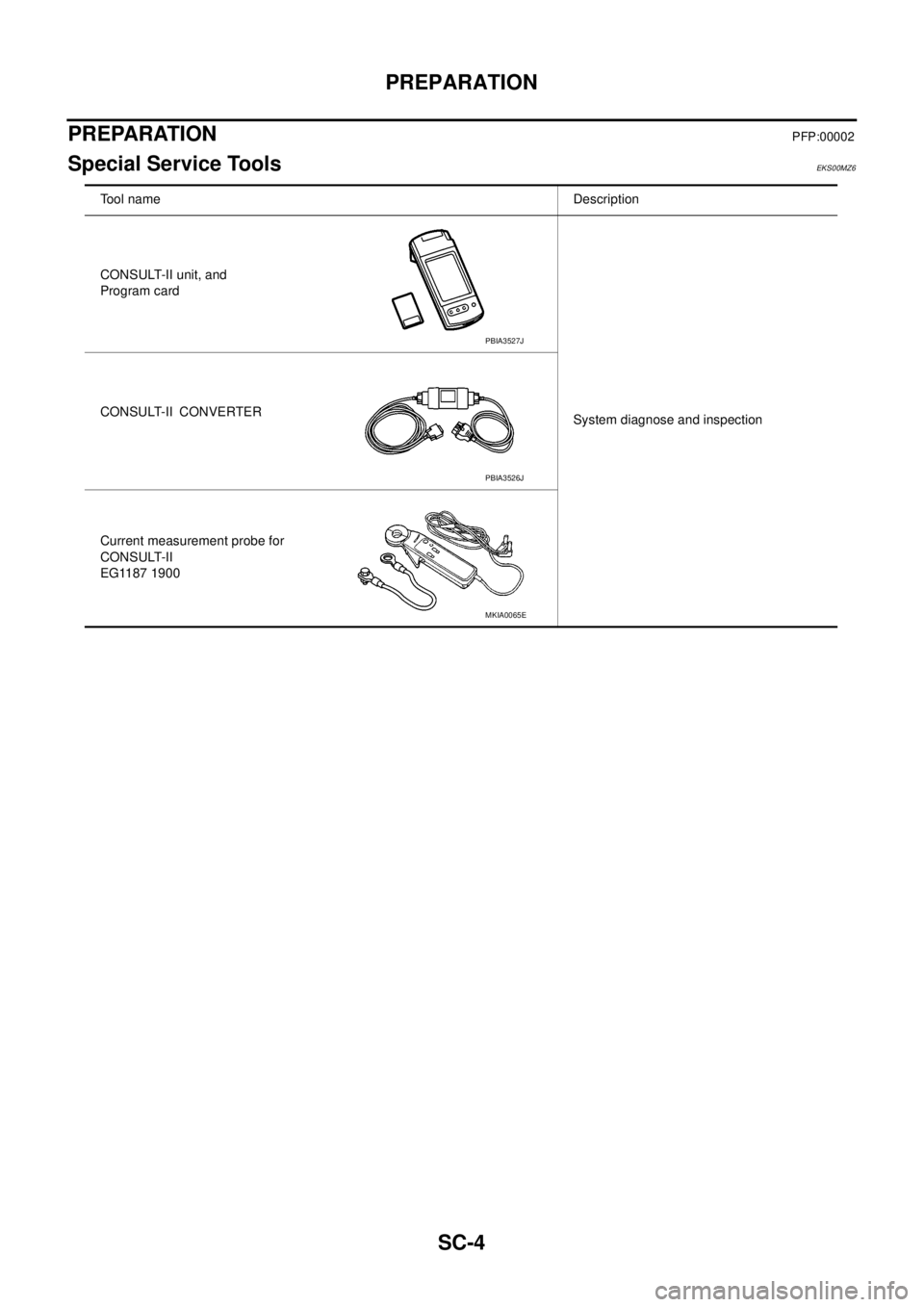
Special Service ToolsEKS00MZ6
Tool name Description
CONSULT-II unit, and
Program card
System diagnose and inspection CONSULT-II CONVERTER
Current measurement probe for
CONSULT-II
EG1187 1900
PBIA3527J
PBIA3526J
MKIA0065E
Page 2870 of 3171
SERVICE DATA AND SPECIFICATIONS (SDS)
SC-37
C
D
E
F
G
H
I
J
L
MA
B
SC
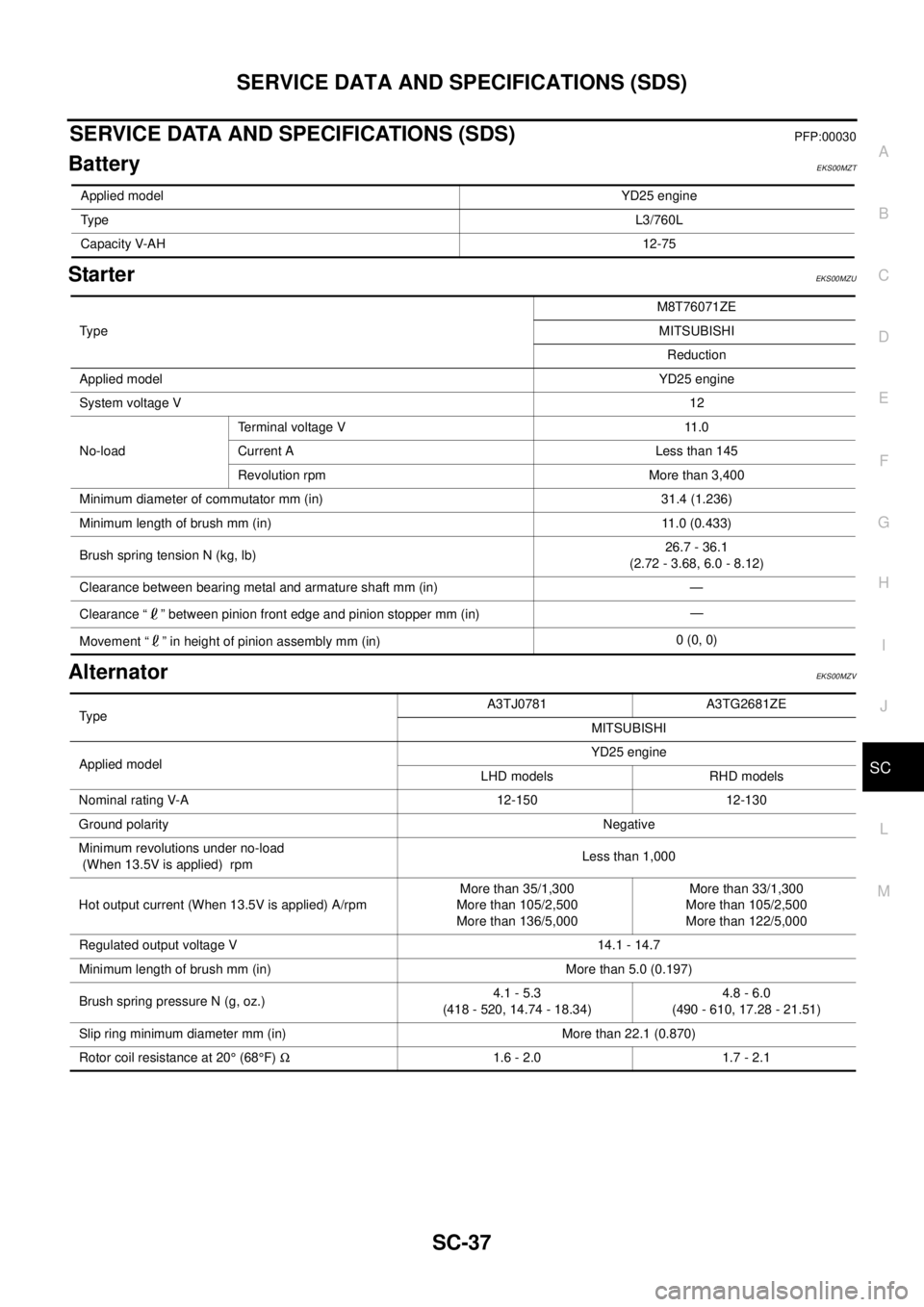
SERVICE DATA AND SPECIFICATIONS (SDS)PFP:00030
BatteryEKS00MZT
StarterEKS00MZU
AlternatorEKS00MZV
Applied modelYD25 engine
TypeL3/760L
Capacity V-AH12-75
Ty p eM8T76071ZE
MITSUBISHI
Reduction
Applied modelYD25 engine
System voltage V12
No-loadTerminal voltage V 11.0
Current A Less than 145
Revolution rpm More than 3,400
Minimum diameter of commutator mm (in) 31.4 (1.236)
Minimum length of brush mm (in) 11.0 (0.433)
Brush spring tension N (kg, lb)26.7 - 36.1
(2.72 - 3.68, 6.0 - 8.12)
Clearance between bearing metal and armature shaft mm (in) —
Clearance “ ” between pinion front edge and pinion stopper mm (in)—
Movement “ ” in height of pinion assembly mm (in)0 (0, 0)
TypeA3TJ0781 A3TG2681ZE
MITSUBISHI
Applied modelYD25 engine
LHD models RHD models
Nominal rating V-A 12-150 12-130
Ground polarityNegative
Minimum revolutions under no-load
(When 13.5V is applied) rpmLess than 1,000
Hot output current (When 13.5V is applied) A/rpmMore than 35/1,300
More than 105/2,500
More than 136/5,000More than 33/1,300
More than 105/2,500
More than 122/5,000
Regulated output voltage V 14.1 - 14.7
Minimum length of brush mm (in) More than 5.0 (0.197)
Brush spring pressure N (g, oz.)4.1 - 5.3
(418 - 520, 14.74 - 18.34)4.8 - 6.0
(490 - 610, 17.28 - 21.51)
Slip ring minimum diameter mm (in) More than 22.1 (0.870)
Rotor coil resistance at 20°(68°F)W1.6 - 2.0 1.7 - 2.1
Page 2871 of 3171

SC-38
SERVICE DATA AND SPECIFICATIONS (SDS)
Page 2872 of 3171

SE-1
SEAT
IBODY
CONTENTS
C
D
E
F
G
H
J
K
L
M
SECTIONSE
A
B
SE
SEAT
PRECAUTIONS .......................................................... 2
Precautions for Supplemental Restraint System
(SRS)“AIRBAG”and“SEATBELTPRE-TEN-
SIONER” .................................................................. 2
Precautions for Work ................................................ 2
PREPARATION ........................................................... 3
Commercial Service Tool ......................................... 3
SQUEAK AND RATTLE TROUBLE DIAGNOSES..... 4
Work Flow ................................................................ 4
CUSTOMER INTERVIEW ..................................... 4
DUPLICATE THE NOISE AND TEST DRIVE ....... 5
CHECK RELATED SERVICE BULLETINS ........... 5
LOCATE THE NOISE AND IDENTIFY THE
ROOT CAUSE ...................................................... 5
REPAIR THE CAUSE ........................................... 5
CONFIRM THE REPAIR ....................................... 6
Generic Squeak and Rattle Troubleshooting ........... 6
INSTRUMENT PANEL .......................................... 6
CENTER CONSOLE ............................................. 6
DOORS ................................................................. 6
TRUNK .................................................................. 7
SUNROOF/HEADLINING ..................................... 7
SEATS ................................................................... 7
UNDERHOOD ....................................................... 7
Diagnostic Worksheet .............................................. 8
POWER SEAT .......................................................... 10Wiring Diagram – SEAT – / For LHD Models ......... 10
Wiring Diagram – SEAT – / For RHD Models ......... 11
HEATED SEAT .......................................................... 12
Description .............................................................. 12
Schematic ............................................................... 13
Wiring Diagram – HSEAT – / For LHD Models ....... 14
Wiring Diagram – HSEAT – / For RHD Models ...... 17
FRONT SEAT ............................................................ 20
Components Parts Drawing .................................... 20
DRIVER SEAT ..................................................... 20
PASSENGER SEAT ............................................ 22
Removal and Installation ........................................ 23
REMOVAL ........................................................... 23
INSTALLATION ................................................... 24
Disassembly and Assembly .................................... 24
SEAT CUSHION (POWER SEAT) ....................... 24
SEAT CUSHION (MANUAL SEAT) ..................... 25
SEATBACK (POWER AND MANUAL SEAT) ...... 26
SEATBACK (FRAT FOLD SEAT) ........................ 27
REAR SEAT .............................................................. 29
Removal and Installation ........................................ 29
JUMP SEAT (KING CAB) .................................... 29
BENCH SEAT LH (DOUBLE CAB) ...................... 30
BENCH SEAT RH (DOUBLE CAB) ..................... 30
Disassembly and Assembly .................................... 32
Page 2873 of 3171

SE-2
PRECAUTIONS
PRECAUTIONS
PFP:00001
Precautions for Supplemental Restraint System (SRS) “AIR BAG” and “SEAT
BELT PRE-TENSIONER”
EIS00CEB
The Supplemental Restraint System such as “AIR BAG” and “SEAT BELT PRE-TENSIONER”, used along
with a front seat belt, helps to reduce the risk or severity of injury to the driver and front passenger for certain
types of collision. Information necessary to service the system safely is included in the SRS and SB section of
this Service Manual.
WARNING:
lTo avoid rendering the SRS inoperative, which could increase the risk of personal injury or death
in the event of a collision which would result in air bag inflation, all maintenance must be per-
formed by an authorized NISSAN/INFINITI dealer.
lImproper maintenance, including incorrect removal and installation of the SRS, can lead to per-
sonal injury caused by unintentional activation of the system. For removal of Spiral Cable and Air
Bag Module, see the SRS section.
lDo not use electrical test equipment on any circuit related to the SRS unless instructed to in this
Service Manual. SRS wiring harnesses can be identified by yellow and/or orange harnesses or
harness connectors.
Precautions for WorkEIS00BAR
lWhen removing or disassembling each component, be careful not to damage or deform it. If a component
may be subject to interference, be sure to protect it with a shop cloth.
lWhen removing (disengaging) components with a screwdriver or similar tool, be sure to wrap the compo-
nent with a shop cloth or vinyl tape to protect it.
lProtect the removed parts with a shop cloth and keep them.
lReplace a deformed or damaged clip.
lIf a part is specified as a non-reusable part, always replace it with new one.
lBe sure to tighten bolts and nuts securely to the specified torque.
lAfter re-installation is completed, be sure to check that each part works normally.
lFollow the steps below to clean components.
–Water soluble foul: Dip a soft cloth into lukewarm water, and wring the water out of the cloth to wipe the
fouled area.
Then rub with a soft and dry cloth.
–Oily foul: Dip a soft cloth into lukewarm water with mild detergent (concentration: within 2 to 3%), and wipe
the fouled area.
Then dip a cloth into fresh water, and wring the water out of the cloth to wipe the detergent off. Then rub
with a soft and dry cloth.
lDo not use organic solvent such as thinner, benzene, alcohol, or gasoline.
lFor genuine leather seats, use a genuine leather seat cleaner.
Page 2874 of 3171
PREPARATION
SE-3
C
D
E
F
G
H
J
K
L
MA
B
SE
PREPARATIONPFP:00002
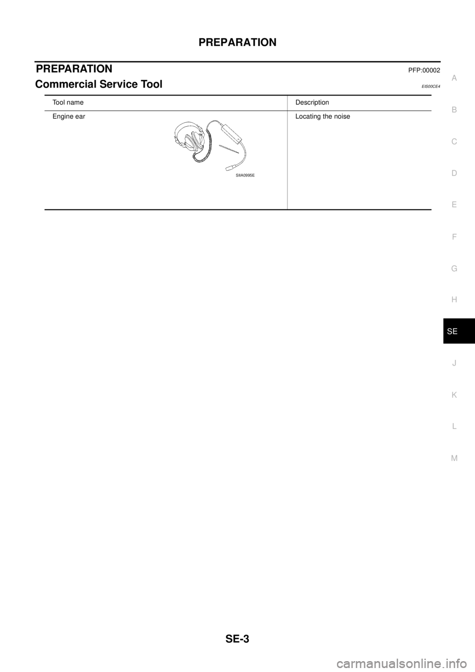
Commercial Service ToolEIS00CE4
Tool name Description
Engine ear Locating the noise
SIIA0995E
Page 2875 of 3171
SE-4
SQUEAK AND RATTLE TROUBLE DIAGNOSES
SQUEAK AND RATTLE TROUBLE DIAGNOSES
PFP:00000
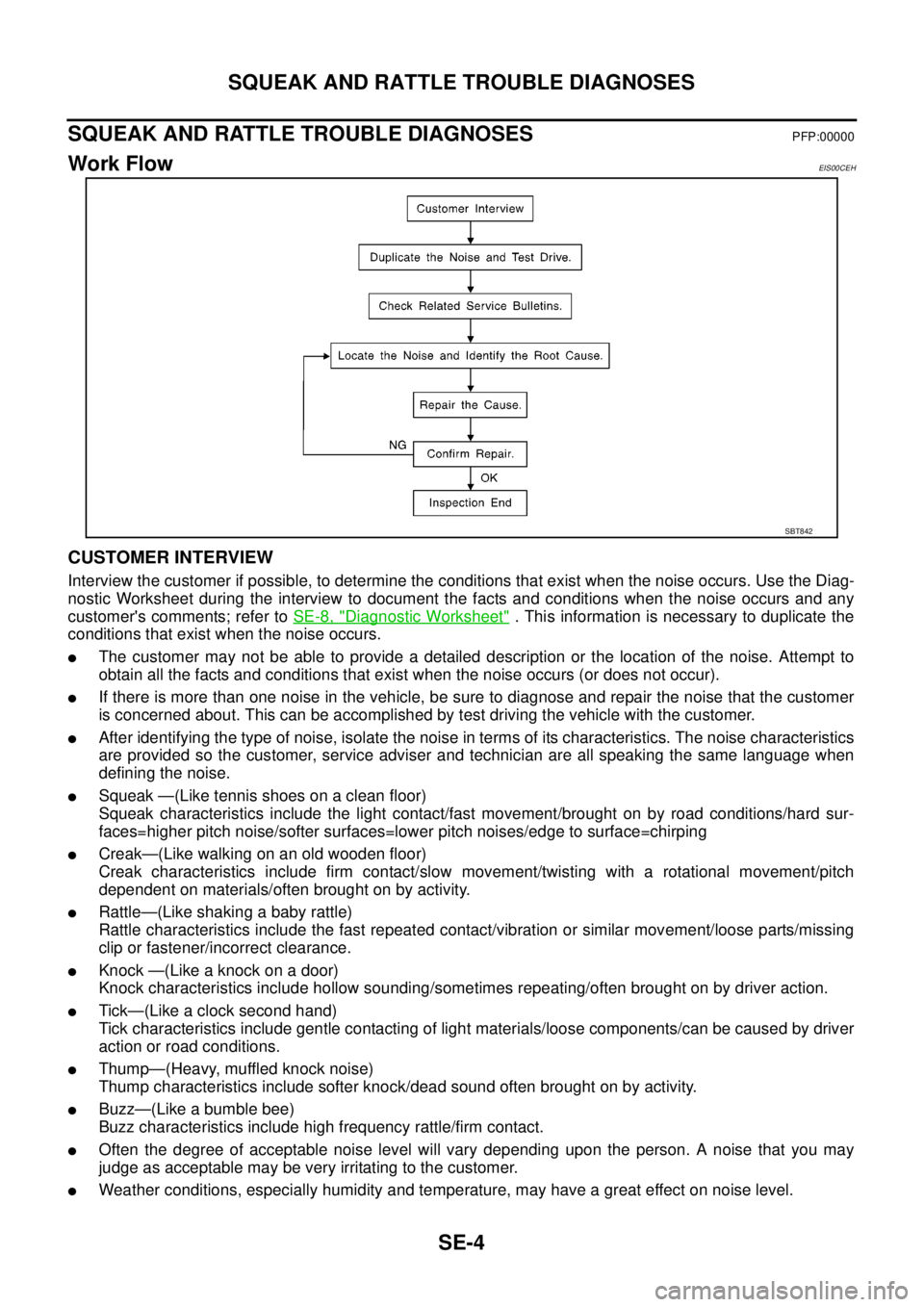
Work FlowEIS00CEH
CUSTOMER INTERVIEW
Interview the customer if possible, to determine the conditions that exist when the noise occurs. Use the Diag-
nostic Worksheet during the interview to document the facts and conditions when the noise occurs and any
customer's comments; refer toSE-8, "
Diagnostic Worksheet". This information is necessary to duplicate the
conditions that exist when the noise occurs.
lThe customer may not be able to provide a detailed description or the location of the noise. Attempt to
obtain all the facts and conditions that exist when the noise occurs (or does not occur).
lIf there is more than one noise in the vehicle, be sure to diagnose and repair the noise that the customer
is concerned about. This can be accomplished by test driving the vehicle with the customer.
lAfter identifying the type of noise, isolate the noise in terms of its characteristics. The noise characteristics
are provided so the customer, service adviser and technician are all speaking the same language when
defining the noise.
lSqueak —(Like tennis shoes on a clean floor)
Squeak characteristics include the light contact/fast movement/brought on by road conditions/hard sur-
faces=higher pitch noise/softer surfaces=lower pitch noises/edge to surface=chirping
lCreak—(Like walking on an old wooden floor)
Creak characteristics include firm contact/slow movement/twisting with a rotational movement/pitch
dependent on materials/often brought on by activity.
lRattle—(Like shaking a baby rattle)
Rattle characteristics include the fast repeated contact/vibration or similar movement/loose parts/missing
clip or fastener/incorrect clearance.
lKnock —(Like a knock on a door)
Knock characteristics include hollow sounding/sometimes repeating/often brought on by driver action.
lTick—(Like a clock second hand)
Tick characteristics include gentle contacting of light materials/loose components/can be caused by driver
action or road conditions.
lThump—(Heavy, muffled knock noise)
Thump characteristics include softer knock/dead sound often brought on by activity.
lBuzz—(Like a bumble bee)
Buzz characteristics include high frequency rattle/firm contact.
lOften the degree of acceptable noise level will vary depending upon the person. A noise that you may
judge as acceptable may be very irritating to the customer.
lWeather conditions, especially humidity and temperature, may have a great effect on noise level.
SBT842