2005 NISSAN NAVARA service
[x] Cancel search: servicePage 1484 of 3171
![NISSAN NAVARA 2005 Repair Workshop Manual EM-102
CYLINDER HEAD
lIf it exceeds the limit, replace valve and/or valve guide.
Valve Guide Replacement
When removing valve guide, replace it with oversized [0.2 mm (0.0008 in)] valve guide.
1. Heat NISSAN NAVARA 2005 Repair Workshop Manual EM-102
CYLINDER HEAD
lIf it exceeds the limit, replace valve and/or valve guide.
Valve Guide Replacement
When removing valve guide, replace it with oversized [0.2 mm (0.0008 in)] valve guide.
1. Heat](/manual-img/5/57362/w960_57362-1483.png)
EM-102
CYLINDER HEAD
lIf it exceeds the limit, replace valve and/or valve guide.
Valve Guide Replacement
When removing valve guide, replace it with oversized [0.2 mm (0.0008 in)] valve guide.
1. Heat cylinder head to 110 to 130°C(230to266°F) in oil bath.
2. Using the valve guide drift (commercial service tool), tap valve
guides out from the combustion chamber side.
WARNING:
Cylinder head contains heat, when working, wear protective
equipment to avoid getting burned.
3. Ream cylinder head valve guide hole with the valve guide
reamer (commercial service tool).
4. Heat cylinder head to 110 to 130°C(230to266°F) in oil bath.
SEM008A
SEM931C
Valve guide hole diameter (for service parts):
10.175 - 10.196 mm (0.4006 - 0.4014 in)
SEM932C
SEM008A
Page 1485 of 3171
CYLINDER HEAD
EM-103
C
D
E
F
G
H
I
J
K
L
MA
EM
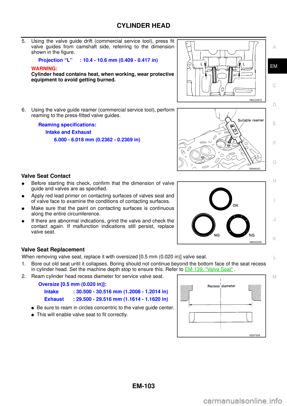
5. Using the valve guide drift (commercial service tool), press fit
valve guides from camshaft side, referring to the dimension
showninthefigure.
WARNING:
Cylinder head contains heat, when working, wear protective
equipment to avoid getting burned.
6. Using the valve guide reamer (commercial service tool), perform
reaming to the press-fitted valve guides.
Valve Seat Contact
lBefore starting this check, confirm that the dimension of valve
guide and valves are as specified.
lApply red lead primer on contacting surfaces of valves seat and
of valve face to examine the conditions of contacting surfaces.
lMake sure that the paint on contacting surfaces is continuous
along the entire circumference.
lIf there are abnormal indications, grind the valve and check the
contact again. If malfunction indications still persist, replace
valve seat.
Valve Seat Replacement
When removing valve seat, replace it with oversized [0.5 mm (0.020 in)] valve seat.
1. Bore out old seat until it collapses. Boring should not continue beyond the bottom face of the seat recess
in cylinder head. Set the machine depth stop to ensure this. Refer toEM-139, "
Valve Seat".
2. Ream cylinder head recess diameter for service valve seat.
lBe sure to ream in circles concentric to the valve guide center.
lThis will enable valve seat to fit correctly.Projection “L” : 10.4 - 10.6 mm (0.409 - 0.417 in)
PBIC2497E
Reaming specifications:
Intake and Exhaust
6.000 - 6.018 mm (0.2362 - 0.2369 in)
SEM932C
SBIA0322E
Oversize [0.5 mm (0.020 in)]:
Intake : 30.500 - 30.516 mm (1.2008 - 1.2014 in)
Exhaust : 29.500 - 29.516 mm (1.1614 - 1.1620 in)
SEM795A
Page 1486 of 3171
EM-104
CYLINDER HEAD
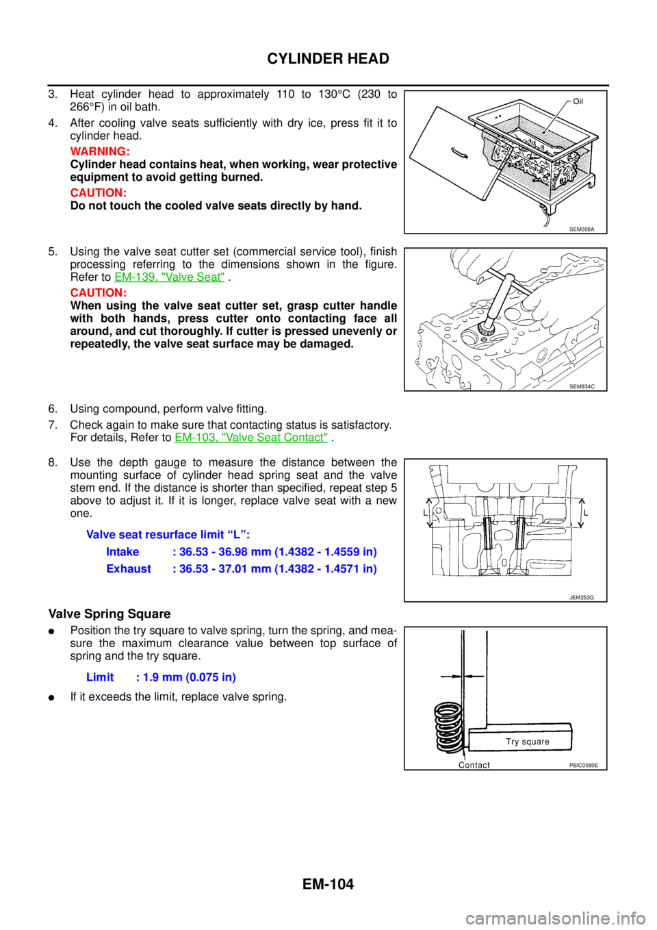
3. Heat cylinder head to approximately 110 to 130°C(230to
266°F) in oil bath.
4. After cooling valve seats sufficiently with dry ice, press fit it to
cylinder head.
WARNING:
Cylinder head contains heat, when working, wear protective
equipment to avoid getting burned.
CAUTION:
Do not touch the cooled valve seats directly by hand.
5. Using the valve seat cutter set (commercial service tool), finish
processing referring to the dimensions shown in the figure.
Refer toEM-139, "
Va l v e S e a t".
CAUTION:
When using the valve seat cutter set, grasp cutter handle
with both hands, press cutter onto contacting face all
around, and cut thoroughly. If cutter is pressed unevenly or
repeatedly, the valve seat surface may be damaged.
6. Using compound, perform valve fitting.
7. Check again to make sure that contacting status is satisfactory.
For details, Refer toEM-103, "
Valve Seat Contact".
8. Use the depth gauge to measure the distance between the
mounting surface of cylinder head spring seat and the valve
stem end. If the distance is shorter than specified, repeat step 5
above to adjust it. If it is longer, replace valve seat with a new
one.
Valve Spring Square
lPosition the try square to valve spring, turn the spring, and mea-
sure the maximum clearance value between top surface of
spring and the try square.
lIf it exceeds the limit, replace valve spring.
SEM008A
SEM934C
Valve seat resurface limit “L”:
Intake : 36.53 - 36.98 mm (1.4382 - 1.4559 in)
Exhaust : 36.53 - 37.01 mm (1.4382 - 1.4571 in)
JEM253G
Limit : 1.9 mm (0.075 in)
PBIC0080E
Page 1493 of 3171
CYLINDER BLOCK
EM-111
C
D
E
F
G
H
I
J
K
L
MA
EM
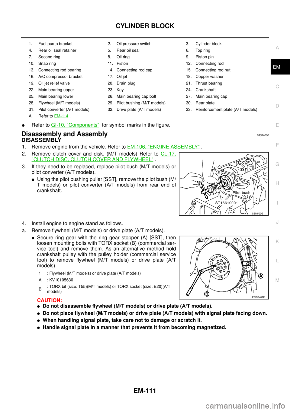
lRefer toGI-10, "Components"for symbol marks in the figure.
Disassembly and AssemblyEBS01E6E
DISASSEMBLY
1. Remove engine from the vehicle. Refer toEM-106, "ENGINE ASSEMBLY".
2. Remove clutch cover and disk. (M/T models) Refer toCL-17,
"CLUTCH DISC, CLUTCH COVER AND FLYWHEEL".
3. If they need to be replaced, replace pilot bush (M/T models) or
pilot converter (A/T models).
lUsing the pilot bushing puller [SST], remove the pilot bush (M/
T models) or pilot converter (A/T models) from rear end of
crankshaft.
4. Install engine to engine stand as follows.
a. Remove flywheel (M/T models) or drive plate (A/T models).
lSecure ring gear with the ring gear stopper (A) [SST], then
loosen mounting bolts with TORX socket (B) (commercial ser-
vice tool) and remove them. As an alternative method hold
crankshaft pulley with the pulley holder (commercial service
tool) to remove flywheel (M/T models) or drive plate (A/T
models).
CAUTION:
lDo not disassemble flywheel (M/T models) or drive plate (A/T models).
lDo not place flywheel (M/T models) or drive plate (A/T models) with signal plate facing down.
lWhen handling signal plate, take care not to damage or scratch it.
lHandle signal plate in a manner that prevents it from becoming magnetized.
1. Fuel pump bracket 2. Oil pressure switch 3. Cylinder block
4. Rear oil seal retainer 5. Rear oil seal 6. Top ring
7. Second ring 8. Oil ring 9. Piston pin
10. Snap ring 11. Piston 12. Connecting rod
13. Connecting rod bearing 14. Connecting rod cap 15. Connecting rod nut
16. A/C compressor bracket 17. Oil jet 18. Copper washer
19. Oil jet relief valve 20. Drain plug 21. Thrust bearing
22. Main bearing upper 23. Key 24. Crankshaft
25. Main bearing lower 26. Main bearing cap bolt 27. Main bearing cap
28. Flywheel (M/T models) 29. Pilot bushing (M/T models) 30. Rear plate
31. Pilot converter (A/T models) 32. Drive plate (A/T models) 33. Reinforcement plate (A/T models)
A. Refer toEM-114
.
SEM500G
1 : Flywheel (M/T models) or drive plate (A/T models)
A : KV10105630
B: TORX bit (size: T55)(M/T models) or TORX socket (size: E20)(A/T
models)
PBIC3482E
Page 1495 of 3171
CYLINDER BLOCK
EM-113
C
D
E
F
G
H
I
J
K
L
MA
EM
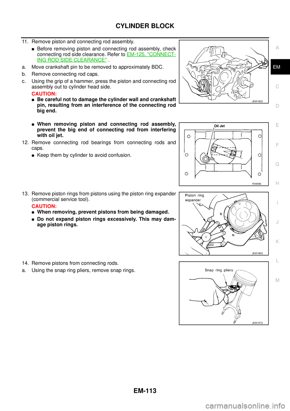
11. Remove piston and connecting rod assembly.
lBefore removing piston and connecting rod assembly, check
connecting rod side clearance. Refer toEM-125, "
CONNECT-
ING ROD SIDE CLEARANCE".
a. Move crankshaft pin to be removed to approximately BDC.
b. Remove connecting rod caps.
c. Using the grip of a hammer, press the piston and connecting rod
assembly out to cylinder head side.
CAUTION:
lBe careful not to damage the cylinder wall and crankshaft
pin, resulting from an interference of the connecting rod
big end.
lWhen removing piston and connecting rod assembly,
prevent the big end of connecting rod from interfering
with oil jet.
12. Remove connecting rod bearings from connecting rods and
caps.
lKeep them by cylinder to avoid confusion.
13. Remove piston rings from pistons using the piston ring expander
(commercial service tool).
CAUTION:
lWhen removing, prevent pistons from being damaged.
lDo not expand piston rings excessively. This may dam-
age piston rings.
14. Remove pistons from connecting rods.
a. Using the snap ring pliers, remove snap rings.
JEM195G
FEM086
JEM196G
JEM197G
Page 1496 of 3171
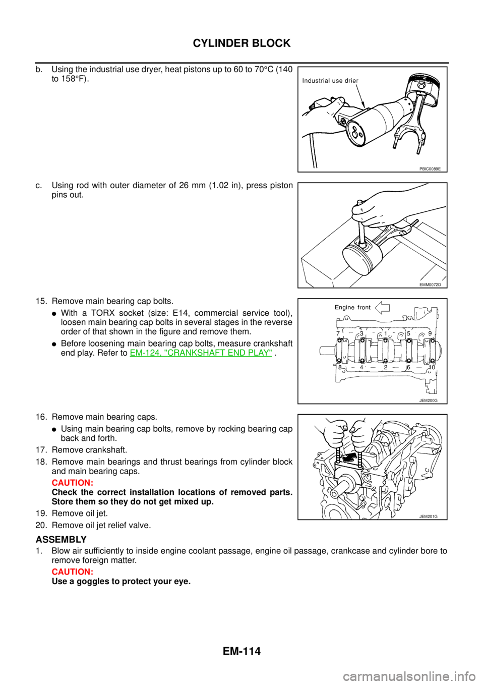
EM-114
CYLINDER BLOCK
b. Using the industrial use dryer, heat pistons up to 60 to 70°C(140
to 158°F).
c. Using rod with outer diameter of 26 mm (1.02 in), press piston
pins out.
15. Remove main bearing cap bolts.
lWith a TORX socket (size: E14, commercial service tool),
loosen main bearing cap bolts in several stages in the reverse
order of that shown in the figure and remove them.
lBefore loosening main bearing cap bolts, measure crankshaft
end play. Refer toEM-124, "
CRANKSHAFT END PLAY".
16. Remove main bearing caps.
lUsing main bearing cap bolts, remove by rocking bearing cap
back and forth.
17. Remove crankshaft.
18. Remove main bearings and thrust bearings from cylinder block
andmainbearingcaps.
CAUTION:
Check the correct installation locations of removed parts.
Store them so they do not get mixed up.
19. Remove oil jet.
20. Remove oil jet relief valve.
ASSEMBLY
1. Blow air sufficiently to inside engine coolant passage, engine oil passage, crankcase and cylinder bore to
remove foreign matter.
CAUTION:
Use a goggles to protect your eye.
PBIC0089E
EMM0072D
JEM200G
JEM201G
Page 1498 of 3171
EM-116
CYLINDER BLOCK
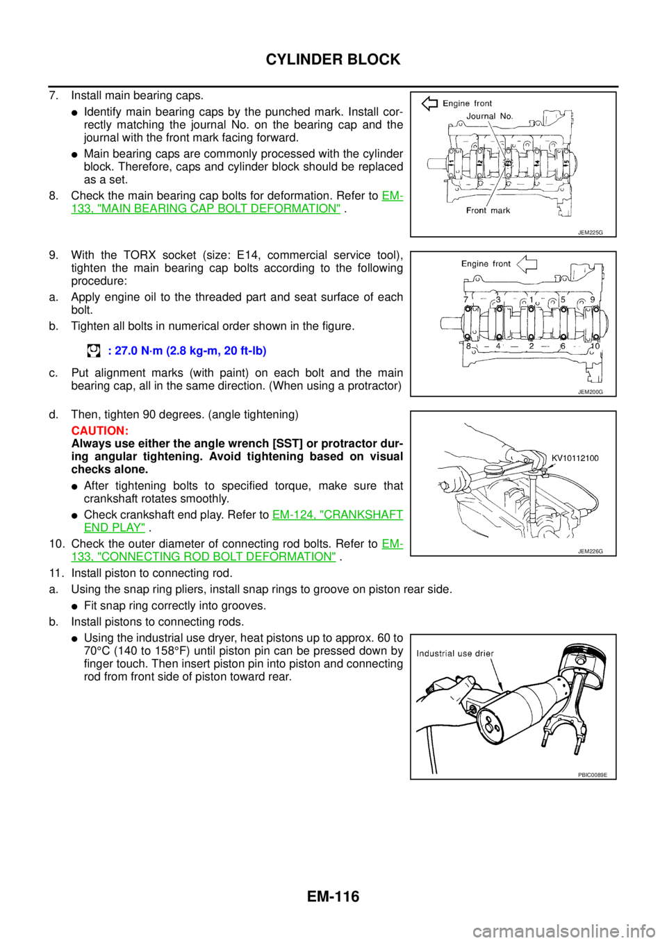
7. Install main bearing caps.
lIdentify main bearing caps by the punched mark. Install cor-
rectly matching the journal No. on the bearing cap and the
journal with the front mark facing forward.
lMain bearing caps are commonly processed with the cylinder
block. Therefore, caps and cylinder block should be replaced
as a set.
8. Check the main bearing cap bolts for deformation. Refer toEM-
133, "MAIN BEARING CAP BOLT DEFORMATION".
9. With the TORX socket (size: E14, commercial service tool),
tighten the main bearing cap bolts according to the following
procedure:
a. Apply engine oil to the threaded part and seat surface of each
bolt.
b. Tighten all bolts in numerical order shown in the figure.
c. Put alignment marks (with paint) on each bolt and the main
bearing cap, all in the same direction. (When using a protractor)
d. Then, tighten 90 degrees. (angle tightening)
CAUTION:
Always use either the angle wrench [SST] or protractor dur-
ing angular tightening. Avoid tightening based on visual
checks alone.
lAfter tightening bolts to specified torque, make sure that
crankshaft rotates smoothly.
lCheck crankshaft end play. Refer toEM-124, "CRANKSHAFT
END PLAY".
10. Check the outer diameter of connecting rod bolts. Refer toEM-
133, "CONNECTING ROD BOLT DEFORMATION".
11. Install piston to connecting rod.
a. Using the snap ring pliers, install snap rings to groove on piston rear side.
lFit snap ring correctly into grooves.
b. Install pistons to connecting rods.
lUsing the industrial use dryer, heat pistons up to approx. 60 to
70°C(140to158°F) until piston pin can be pressed down by
finger touch. Then insert piston pin into piston and connecting
rod from front side of piston toward rear.
JEM225G
: 27.0 N·m (2.8 kg-m, 20 ft-lb)
JEM200G
JEM226G
PBIC0089E
Page 1499 of 3171
CYLINDER BLOCK
EM-117
C
D
E
F
G
H
I
J
K
L
MA
EM
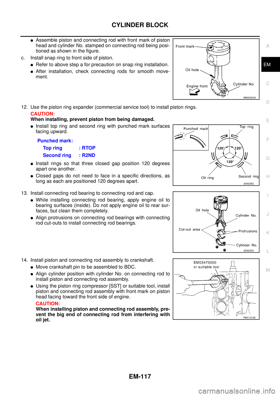
lAssemble piston and connecting rod with front mark of piston
head and cylinder No. stamped on connecting rod being posi-
tioned as shown in the figure.
c. Install snap ring to front side of piston.
lRefer to above step a for precaution on snap ring installation.
lAfter installation, check connecting rods for smooth move-
ment.
12. Use the piston ring expander (commercial service tool) to install piston rings.
CAUTION:
When installing, prevent piston from being damaged.
lInstall top ring and second ring with punched mark surfaces
facing upward.
lInstall rings so that three closed gap position 120 degrees
apart one another.
lClosed gaps do not need to face in a specific directions, as
long as each are positioned 120 degrees apart.
13. Install connecting rod bearing to connecting rod and cap.
lWhile installing connecting rod bearing, apply engine oil to
bearing surfaces (inside). Do not apply engine oil to rear sur-
faces, but clean them completely.
lAlign protrusions on connecting rod bearings with connecting
rod cut-outs to install connecting rod bearings.
14. Install piston and connecting rod assembly to crankshaft.
lMove crankshaft pin to be assembled to BDC.
lAlign cylinder position with cylinder No. on connecting rod to
install piston and connecting rod assembly.
lUsing the piston ring compressor [SST] or suitable tool, install
piston and connecting rod assembly with front mark on piston
head facing toward the front side of engine.
CAUTION:
When installing piston and connecting rod assembly, pre-
vent the big end of connecting rod from interfering with
oil jet.
MBIA0024E
Punched mark:
To p r i n g : R TO P
Second ring : R2ND
JEM228G
JEM229G
PBIC1619E