Page 1385 of 3171

EM-3
C
D
E
F
G
H
I
J
K
L
M
EMA BEARING .......................................................... 132
MAIN BEARING CAP BOLT DEFORMATION .. 133
CONNECTING ROD BOLT DEFORMATION .... 133
OIL JET ............................................................. 133
OIL JET RELIEF VALVE ................................... 133
FLYWHEEL DEFLECTION ............................... 134
MOVEMENT AMOUNT OF FLYWHEEL ........... 134
DRIVE PLATE ................................................... 134
SERVICE DATA AND SPECIFICATIONS (SDS) .... 135
Standard and Limit ............................................... 135
GENERAL SPECIFICATIONS .......................... 135
INTAKE MANIFOLD AND EXHAUST MANI-FOLD .................................................................135
DRIVE BELTS ...................................................135
CYLINDER HEAD .............................................136
VALVE ...............................................................136
CAMSHAFT .......................................................140
CYLINDER BLOCK ...........................................141
PISTON, PISTON RING AND PISTON PIN ......141
CONNECTING ROD .........................................144
CRANKSHAFT ..................................................144
AVAILABLE MAIN BEARING ............................145
AVAILABLE CONNECTING ROD BEARING ....145
MISCELLANEOUS COMPONENTS .................145
Page 1388 of 3171
EM-6
PREPARATION
PREPARATION
PFP:00002
Special Service ToolsEBS01E5O
Tool number
Tool nameDescription
KV10115600
Valve oil seal driftInstalling valve oil seal
UsesideA.
Side A
a: 20 (0.79) dia.
b: 13 (0.51) dia.
c: 10.3 (0.406) dia.
d: 8 (0.31) dia.
e: 10.7 (0.421)
f: 5 (0.20)
Unit: mm (in)
KV10107902
Valve oil seal puller
1. KV10116100
Valve oil seal puller adapterRemoving valve oil seal
KV11103000
Pulley pullerRemoving crankshaft pulley
ED19600610
Compression gauge adapterChecking compression pressure
KV101056S0
Ring gear stopper
1. KV10105630
Adapter
2. KV10105610
PlatePreventing crankshaft from rotating
a: 3 (0.12)
b: 6.4 (0.252)
c: 2.8 (0.110)
d: 6.6 (0.260)
e: 107 (4.21)
f: 14 (0.55)
g: 20 (0.79)
h: 14 (0.55) dia.
Unit: mm (in)
KV101151S0
Lifter stopper set
1. KV10115110
Camshaft pliers
2. KV10115120
Lifter stopperChanging adjusting shim
NT603
S-NT605
NT676
ZZA1188D
NT617
NT041
Page 1390 of 3171
EM-8
PREPARATION
Commercial Service Tools
EBS01E5P
KV11106020
Hexagon wrenchRemoving and installing slack guide
a: 6 mm (0.24 in) (Face to face)
b: 20 mm (0.79 in)
KV11106030
Positioning stopper pinFixing fuel pump sprocket
a: 6 mm (0.24 in) dia.
b: 80 mm (3.15 in)
KV11106040
TORX wrenchRemoving and installing fuel pump sprocket
nut
a: T70
b: 26 mm (1.02 in)
KV11106050
Hexagonal wrenchRemoving and installing fuel pump sprocket
a: 6 mm (0.24 in) (Face to face)
b: 42 mm (1.65 in)
KV11106060
Sprocket holderHolding fuel pump sprocket Tool number
Tool nameDescription
NT803
NT804
NT805
SBIA0224E
SBIA0225E
Tool nameDescription
Valve seat cutter set Finishing valve seat dimensions
Piston ring expander Removing and installing piston ring
NT048
NT030
Page 1433 of 3171
![NISSAN NAVARA 2005 Repair Workshop Manual FUEL PUMP
EM-51
C
D
E
F
G
H
I
J
K
L
MA
EM
8. Using the sprocket holder [SST], hold fuel pump sprocket to pre-
vent falling.
lFor sprocket holder, use KV11106060 machined as shown in
the figure, becaus NISSAN NAVARA 2005 Repair Workshop Manual FUEL PUMP
EM-51
C
D
E
F
G
H
I
J
K
L
MA
EM
8. Using the sprocket holder [SST], hold fuel pump sprocket to pre-
vent falling.
lFor sprocket holder, use KV11106060 machined as shown in
the figure, becaus](/manual-img/5/57362/w960_57362-1432.png)
FUEL PUMP
EM-51
C
D
E
F
G
H
I
J
K
L
MA
EM
8. Using the sprocket holder [SST], hold fuel pump sprocket to pre-
vent falling.
lFor sprocket holder, use KV11106060 machined as shown in
the figure, because the previous bore is not fitting.
lWhen the sprocket holder is installed, if the positioning stop-
per pin [SST] interferes, pull out the positioning stopper pin
approximately 10 mm (0.39 in), then install it.
lAfter the sprocket holder is installed temporarily, tighten the
sprocket holder after making extension bar and TORX socket
(size: E10) (commercial service tool) insert into the machined
bore.
lThe length of the sprocket holder mounting bolts should be
approximately 15 mm (0.59 in) (M6 thread length).
lMake sure that the a- and b-faces of the sprocket holder con-
tact the bottom side of the sprocket (small diameter side).
CAUTION:
Do not remove the sprocket holder [SST] until fuel pump is installed.
lAfter the sprocket holder is installed, pull out the positioning
stopper pin from fuel pump sprocket.
9. Using the extension bar and the TORX socket (size: E10) (com-
mercial service tool), remove the tightening bolts.
CAUTION:
Do not disassemble or adjust fuel pump.
10. Remove the fuel pump toward the rear of engine.
CAUTION:
For removal, be careful not to drop the seal washer into the engine.
NOTE:
The seal washer of the tightening bolts cannot be reused.
11. Remove adjusting shim.
12. Attach a suitable tool in the M8 bolt hole on coupling.
SBIA0217E
PBIC2534E
MBIA0075E
PBIC2405E
Page 1436 of 3171

EM-54
FUEL PUMP
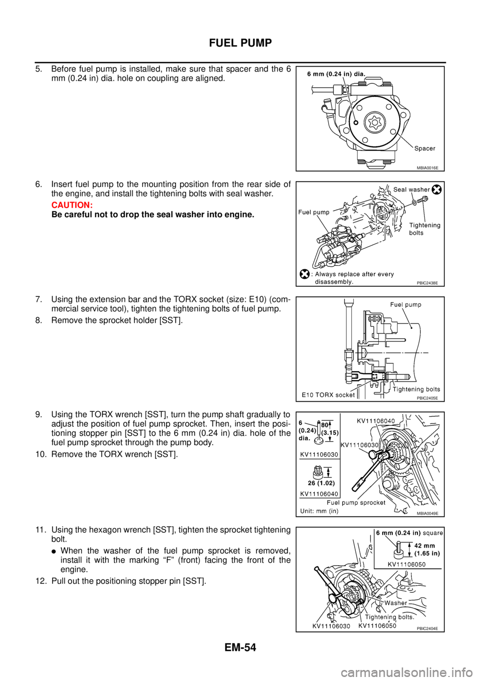
5. Before fuel pump is installed, make sure that spacer and the 6
mm (0.24 in) dia. hole on coupling are aligned.
6. Insert fuel pump to the mounting position from the rear side of
the engine, and install the tightening bolts with seal washer.
CAUTION:
Be careful not to drop the seal washer into engine.
7. Using the extension bar and the TORX socket (size: E10) (com-
mercial service tool), tighten the tightening bolts of fuel pump.
8. Remove the sprocket holder [SST].
9. Using the TORX wrench [SST], turn the pump shaft gradually to
adjust the position of fuel pump sprocket. Then, insert the posi-
tioning stopper pin [SST] to the 6 mm (0.24 in) dia. hole of the
fuel pump sprocket through the pump body.
10. Remove the TORX wrench [SST].
11. Using the hexagon wrench [SST], tighten the sprocket tightening
bolt.
lWhen the washer of the fuel pump sprocket is removed,
install it with the marking “F” (front) facing the front of the
engine.
12. Pull out the positioning stopper pin [SST].
MBIA0016E
PBIC2438E
PBIC2405E
MBIA0049E
PBIC2404E
Page 1463 of 3171
![NISSAN NAVARA 2005 Repair Workshop Manual PRIMARY TIMING CHAIN
EM-81
C
D
E
F
G
H
I
J
K
L
MA
EM
c. Using the pulley puller [SST], remove crankshaft pulley.
lUse two M6 bolts with approx. 60 mm (2.36 in) shank length
for securing crankshaft pul NISSAN NAVARA 2005 Repair Workshop Manual PRIMARY TIMING CHAIN
EM-81
C
D
E
F
G
H
I
J
K
L
MA
EM
c. Using the pulley puller [SST], remove crankshaft pulley.
lUse two M6 bolts with approx. 60 mm (2.36 in) shank length
for securing crankshaft pul](/manual-img/5/57362/w960_57362-1462.png)
PRIMARY TIMING CHAIN
EM-81
C
D
E
F
G
H
I
J
K
L
MA
EM
c. Using the pulley puller [SST], remove crankshaft pulley.
lUse two M6 bolts with approx. 60 mm (2.36 in) shank length
for securing crankshaft pulley.
9. Remove oil pump housing.
lLoosen bolts in reverse order of that shown in the figure and
remove them.
lU s e t h e s e a l c u t t e r [ S S T: K V 1 0 1111 0 0 ] e t c . f o r r e m o v a l .
10. Remove crankshaft gear.
lRemove crankshaft gear (1) with the following procedure
(4WD models).
a. Make sure that No.1 piston is TDC on its compression stroke.
b. Turn the idler sub gear (3) counterclockwise with snap ring plier
(B) or suitable tool for aligning idler sub gear (3) and idler main
gear (2).
lIf idler gear rotates, hold the flat faces on balancer drive shaft
front end (4).
c. Install internal mechanism securing bolt and plate (Service part:
13012 EB30A and 13013 EB30A) (A) and tighten to the speci-
fied torque.
CAUTION:
lDo not loosen idler gear mounting bolt (5).
lOnly use the genuine internal mechanism securing bolt
and plate (A), or the idler gear (2) and (3) will be damaged.
lDo not remove internal mechanism securing bolt and
plate (A) from idler gear (2) and (3) until crankshaft gear
(1) and all of the parts in connection have been installed.
lIf internal mechanism securing bolt and plate (A) is not
installed, internal mechanism of idler gear (2) and (3) will
disengage after crankshaft gear (1) is removed. This will prohibit the balancer unit from being
reusable.
d. Apply mating marks (C) to crankshaft gear (1) and idler sub gear (3).
e. Remove crankshaft gear (1).
11. Remove front oil seal from oil pump housing.
lPunch out the seal off from the back surface of the oil pump housing using a flat-bladed screwdriver.
CAUTION:
Be careful not to damage oil pump housing.
JEM132G
PBIC3470E
: 4.0 N·m (0.41 kg-m, 35 in-lb)
PBIC3471E
Page 1471 of 3171
PRIMARY TIMING CHAIN
EM-89
C
D
E
F
G
H
I
J
K
L
MA
EM
–Align crankshaft gear (1) mating mark and idler sub gear (3)
mating mark (C).
–Remove internal mechanism securing bolt and plate (Service
part: 13012 EB30A and 13013 EB30A) (A).
–If new balancer unit (2) is used, align matching marks (B) of
each gear as shown in the figure.
–Remove securing-bolt-and-plate (A) and securing pin (C) after
installing crankshaft gear (1).
15. Install oil pump housing.
a. Apply a continuous bead of liquid gasket with the tube presser
[SST: WS39930000] as shown in the figure.
A: Leave the start and end areas of the bead slightly protruding
from the surface.
B: Apply liquid gasket along upper end surface of oil pump hous-
ing.
2 : Idler main gear
4 : Balancer drive shaft front end
5 : Idler gear mounting bolt (do not loosen)
B : Snap ring plier
PBIC3471E
PBIC3475E
JEM144G
Page 1474 of 3171

EM-92
CYLINDER HEAD
CYLINDER HEAD
PFP:11041
On-Vehicle ServiceEBS01E6A
CHECKING COMPRESSION PRESSURE
1. Warm up engine thoroughly. Then, stop it.
2. Using CONSULT-II, make sure no error codes are indicated for self-diagnosis items. Refer toEC-38,
"Basic Inspection".
lDo not disconnect CONSULT-II until the end of this operation; it will be used to check engine rpm and
for error detection at the end of this operation.
3. Disconnect the battery cable from the negative terminal.
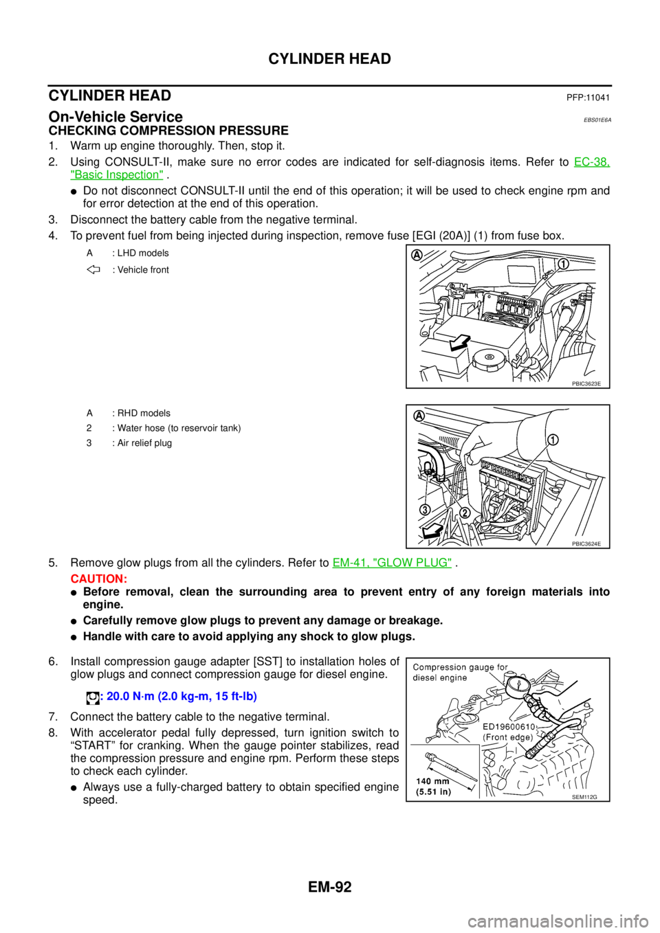
4. To prevent fuel from being injected during inspection, remove fuse [EGI (20A)] (1) from fuse box.
5. Remove glow plugs from all the cylinders. Refer toEM-41, "
GLOW PLUG".
CAUTION:
lBefore removal, clean the surrounding area to prevent entry of any foreign materials into
engine.
lCarefully remove glow plugs to prevent any damage or breakage.
lHandle with care to avoid applying any shock to glow plugs.
6. Install compression gauge adapter [SST] to installation holes of
glow plugs and connect compression gauge for diesel engine.
7. Connect the battery cable to the negative terminal.
8. With accelerator pedal fully depressed, turn ignition switch to
“START” for cranking. When the gauge pointer stabilizes, read
the compression pressure and engine rpm. Perform these steps
to check each cylinder.
lAlways use a fully-charged battery to obtain specified engine
speed.
A : LHD models
: Vehicle front
PBIC3623E
A : RHD models
2 : Water hose (to reservoir tank)
3:Airreliefplug
PBIC3624E
: 20.0 N·m (2.0 kg-m, 15 ft-lb)
SEM112G