2005 NISSAN NAVARA service
[x] Cancel search: servicePage 1338 of 3171
![NISSAN NAVARA 2005 Repair Workshop Manual EC-358
SERVICE DATA AND SPECIFICATIONS (SDS)
Fuel Pump
EBS01KNE
Resistance [at 10 - 60°C (50 - 140°F)] 1.5 - 3.0W NISSAN NAVARA 2005 Repair Workshop Manual EC-358
SERVICE DATA AND SPECIFICATIONS (SDS)
Fuel Pump
EBS01KNE
Resistance [at 10 - 60°C (50 - 140°F)] 1.5 - 3.0W](/manual-img/5/57362/w960_57362-1337.png)
EC-358
SERVICE DATA AND SPECIFICATIONS (SDS)
Fuel Pump
EBS01KNE
Resistance [at 10 - 60°C (50 - 140°F)] 1.5 - 3.0W
Page 1339 of 3171
EI-1
EXTERIOR & INTERIOR
IBODY
CONTENTS
C
D
E
F
G
H
J
K
L
M
SECTIONEI
A
B
EI
EXTERIOR & INTERIOR
PRECAUTIONS .......................................................... 3
Service Notice .......................................................... 3
Precautions for Supplemental Restraint System
(SRS)“AIRBAG”and“SEATBELTPRE-TEN-
SIONER” .................................................................. 3
Precautions for SRS “AIR BAG” and “SEAT BELT
PRE-TENSIONER” Service ..................................... 3
Precautions for Procedures without Cowl Top Cover..... 4
PREPARATION ........................................................... 5
Commercial Service Tools ........................................ 5
SQUEAK AND RATTLE TROUBLE DIAGNOSES..... 6
Work Flow ................................................................ 6
CUSTOMER INTERVIEW ..................................... 6
DUPLICATE THE NOISE AND TEST DRIVE ....... 7
CHECK RELATED SERVICE BULLETINS ........... 7
LOCATE THE NOISE AND IDENTIFY THE
ROOT CAUSE ...................................................... 7
REPAIR THE CAUSE ........................................... 7
CONFIRM THE REPAIR ....................................... 7
Generic Squeak and Rattle Troubleshooting ........... 7
INSTRUMENT PANEL .......................................... 7
CENTER CONSOLE ............................................. 8
DOORS ................................................................. 8
TRUNK .................................................................. 8
SUNROOF/HEADLINING ..................................... 8
OVERHEAD CONSOLE (FRONT AND REAR)..... 8
SEATS ................................................................... 9
UNDERHOOD ....................................................... 9
Diagnostic Worksheet ............................................ 10
CLIP AND FASTENER ............................................. 12
Clip and Fastener ................................................... 12
FRONT BUMPER ..................................................... 15
Removal and Installation ........................................ 15
FRONT BUMPER ............................................... 15
REAR BUMPER ....................................................... 17
Removal and Installation ........................................ 17
REMOVAL ........................................................... 17
INSTALLATION ................................................... 18FRONT GRILLE ........................................................ 19
Removal and Installation ........................................ 19
REMOVAL ........................................................... 19
INSTALLATION ................................................... 19
COWL TOP ............................................................... 20
Removal and Installation ........................................ 20
REMOVAL ........................................................... 20
INSTALLATION ................................................... 20
FENDER PROTECTOR ............................................ 21
Components ........................................................... 21
Removal and Installation of Front Fender Protector... 22
REMOVAL ........................................................... 22
INSTALLATION ................................................... 22
Removal and Installation of Rear Fender Protector... 22
REMOVAL ........................................................... 22
INSTALLATION ................................................... 22
MUDGUARD ............................................................. 23
Removal and Installation ........................................ 23
RUNNING BOARDS ................................................. 24
Removal and Installation ........................................ 24
REMOVAL ........................................................... 25
INSTALLATION ................................................... 25
ROOF RACK ............................................................. 26
Removal and Installation ........................................ 26
REMOVAL ........................................................... 26
INSTALLATION ................................................... 26
DOOR OUTSIDE MOLDING ..................................... 27
Removal and Installation ........................................ 27
FRONT DOOR OUTSIDE MOLDING .................. 27
SIDE GUARD MOLDING .......................................... 28
Removal and Installation ........................................ 28
REMOVAL ........................................................... 29
INSTALLATION ................................................... 29
DOOR FINISHER ...................................................... 30
Removal and Installation ........................................ 30
FRONT DOOR .................................................... 30
REAR DOOR - DOUBLE CAB ............................ 31
REAR DOOR - KING CAB .................................. 32
BODY SIDE TRIM ..................................................... 33
Components ........................................................... 33
Page 1341 of 3171
PRECAUTIONS
EI-3
C
D
E
F
G
H
J
K
L
MA
B
EI
PRECAUTIONSPFP:00001
Service NoticeEIS00DY1
lWhen removing or installing various parts, place a cloth or padding on the vehicle body to prevent
scratches.
lHandle trim, molding, instruments, grille, etc. carefully during removing or installing. Be careful not to soil
or damage them.
lApply sealing compound where necessary when installing parts.
lWhen applying sealing compound, be careful that the sealing compound does not protrude from parts.
lWhen replacing any metal parts (for example body outer panel, members, etc.), be sure to take rust pre-
vention measures.
Precautions for Supplemental Restraint System (SRS) “AIR BAG” and “SEAT
BELT PRE-TENSIONER”
EIS00DZ5
The Supplemental Restraint System such as “AIR BAG” and “SEAT BELT PRE-TENSIONER”, used along
with a front seat belt, helps to reduce the risk or severity of injury to the driver and front passenger for certain
types of collision. Information necessary to service the system safely is included in the SRS and SB section of
this Service Manual.
WARNING:
lTo avoid rendering the SRS inoperative, which could increase the risk of personal injury or death
in the event of a collision which would result in air bag inflation, all maintenance must be per-
formed by an authorized NISSAN/INFINITI dealer.
lImproper maintenance, including incorrect removal and installation of the SRS, can lead to per-
sonal injury caused by unintentional activation of the system. For removal of Spiral Cable and Air
Bag Module, see the SRS section.
lDo not use electrical test equipment on any circuit related to the SRS unless instructed to in this
Service Manual. SRS wiring harnesses can be identified by yellow and/or orange harnesses or
harness connectors.
Precautions for SRS “AIR BAG” and “SEAT BELT PRE-TENSIONER” ServiceEIS00DZ2
lDo not use electrical test equipment to check SRS circuits unless instructed to in this Service Manual.
lBefore servicing the SRS, turn ignition switch OFF, disconnect both battery cables and wait at least 3 min-
utes.
For approximately 3 minutes after the cables are removed, it is still possible for the air bag and seat belt
pre-tensioner to deploy. Therefore, do not work on any SRS connectors or wires until at least 3 minutes
have passed.
lThe air bag diagnosis sensor unit must always be installed with the arrow marks “Ü” pointing toward the
front of the vehicle for proper operation. Also check the air bag diagnosis sensor unit for cracks, deformi-
ties or rust before installation and replace as required.
lThe spiral cable must be aligned with the neutral position since its rotations are limited. Do not attempt to
turn steering wheel or column after removal of steering gear.
lHandle air bag module carefully. Always place driver and front passenger air bag modules with the pad
side facing upward and seat mounted front side air bag module standing with the stud bolt side facing
down.
lConduct self-diagnosis to check entire SRS for proper function after replacing any components.
lAfter air bag inflates, the front instrument panel assembly should be replaced if damaged.
Page 1343 of 3171
PREPARATION
EI-5
C
D
E
F
G
H
J
K
L
MA
B
EI
PREPARATIONPFP:00002
Commercial Service ToolsEIS00DY4
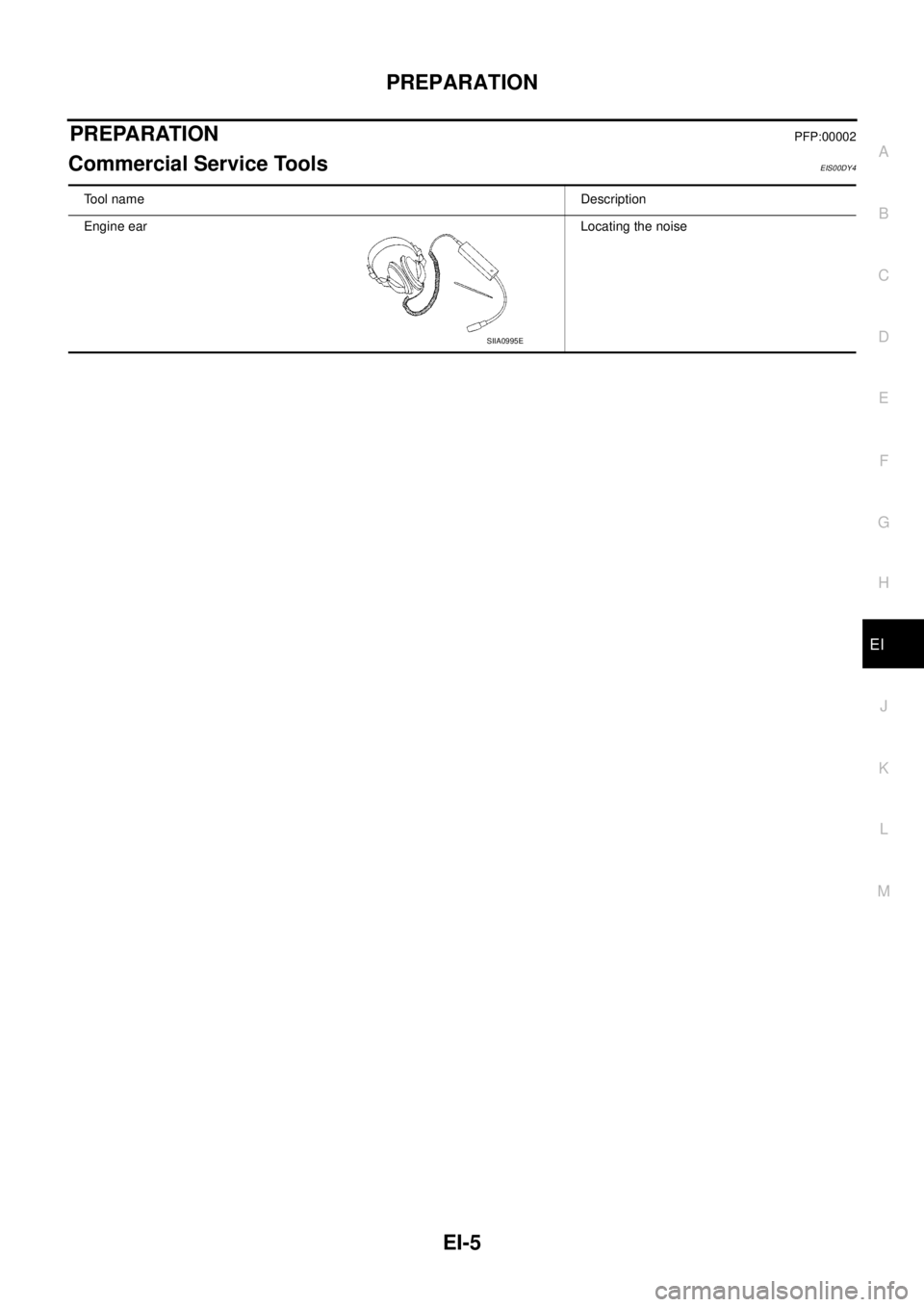
Tool nameDescription
Engine earLocating the noise
SIIA0995E
Page 1344 of 3171
EI-6
SQUEAK AND RATTLE TROUBLE DIAGNOSES
SQUEAK AND RATTLE TROUBLE DIAGNOSES
PFP:00000
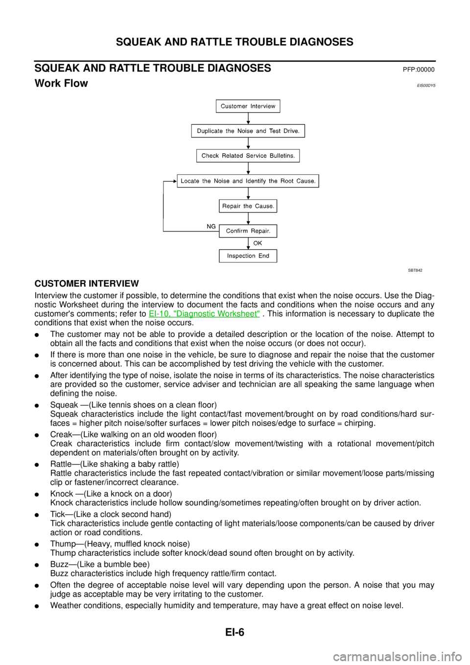
Work FlowEIS00DY5
CUSTOMER INTERVIEW
Interview the customer if possible, to determine the conditions that exist when the noise occurs. Use the Diag-
nostic Worksheet during the interview to document the facts and conditions when the noise occurs and any
customer's comments; refer toEI-10, "
Diagnostic Worksheet". This information is necessary to duplicate the
conditions that exist when the noise occurs.
lThe customer may not be able to provide a detailed description or the location of the noise. Attempt to
obtain all the facts and conditions that exist when the noise occurs (or does not occur).
lIf there is more than one noise in the vehicle, be sure to diagnose and repair the noise that the customer
is concerned about. This can be accomplished by test driving the vehicle with the customer.
lAfter identifying the type of noise, isolate the noise in terms of its characteristics. The noise characteristics
are provided so the customer, service adviser and technician are all speaking the same language when
defining the noise.
lSqueak —(Like tennis shoes on a clean floor)
Squeak characteristics include the light contact/fast movement/brought on by road conditions/hard sur-
faces = higher pitch noise/softer surfaces = lower pitch noises/edge to surface = chirping.
lCreak—(Like walking on an old wooden floor)
Creak characteristics include firm contact/slow movement/twisting with a rotational movement/pitch
dependent on materials/often brought on by activity.
lRattle—(Like shaking a baby rattle)
Rattle characteristics include the fast repeated contact/vibration or similar movement/loose parts/missing
clip or fastener/incorrect clearance.
lKnock —(Like a knock on a door)
Knock characteristics include hollow sounding/sometimes repeating/often brought on by driver action.
lTick—(Like a clock second hand)
Tick characteristics include gentle contacting of light materials/loose components/can be caused by driver
action or road conditions.
lThump—(Heavy, muffled knock noise)
Thump characteristics include softer knock/dead sound often brought on by activity.
lBuzz—(Like a bumble bee)
Buzz characteristics include high frequency rattle/firm contact.
lOften the degree of acceptable noise level will vary depending upon the person. A noise that you may
judge as acceptable may be very irritating to the customer.
lWeather conditions, especially humidity and temperature, may have a great effect on noise level.
SBT842
Page 1345 of 3171
SQUEAK AND RATTLE TROUBLE DIAGNOSES
EI-7
C
D
E
F
G
H
J
K
L
MA
B
EI
DUPLICATE THE NOISE AND TEST DRIVE
If possible, drive the vehicle with the customer until the noise is duplicated. Note any additional information on
the Diagnostic Worksheet regarding the conditions or location of the noise. This information can be used to
duplicate the same conditions when you confirm the repair.
If the noise can be duplicated easily during the test drive, to help identify the source of the noise, try to dupli-
cate the noise with the vehicle stopped by doing one or all of the following:
1) Close a door.
2) Tap or push/pull around the area where the noise appears to be coming from.
3) Rev the engine.
4) Use a floor jack to recreate vehicle “twist”.
5) At idle, apply engine load (electrical load, half-clutch on M/T model, drive position on A/T model).
6) Raisethevehicleonahoistandhitatirewitharubberhammer.
lDrive the vehicle and attempt to duplicate the conditions the customer states exist when the noise occurs.
lIf it is difficult to duplicate the noise, drive the vehicle slowly on an undulating or rough road to stress the
vehicle body.
CHECK RELATED SERVICE BULLETINS
After verifying the customer concern or symptom, check ASIST for Technical Service Bulletins (TSBs) related
to that concern or symptom.
If a TSB relates to the symptom, follow the procedure to repair the noise.
LOCATE THE NOISE AND IDENTIFY THE ROOT CAUSE
1. Narrow down the noise to a general area.To help pinpoint the source of the noise, use a listening tool
(Engine Ear and mechanic's stethoscope).
2. Narrow down the noise to a more specific area and identify the cause of the noise by:
lremoving the components in the area that you suspect the noise is coming from.
Do not use too much force when removing clips and fasteners, otherwise clips and fasteners can be bro-
ken or lost during the repair, resulting in the creation of new noise.
ltapping or pushing/pulling the component that you suspect is causing the noise.
Do not tap or push/pull the component with excessive force, otherwise the noise will be eliminated only
temporarily.
lfeeling for a vibration with your hand by touching the component(s) that you suspect is (are) causing the
noise.
lplacing a piece of paper between components that you suspect are causing the noise.
llooking for loose components and contact marks.
Refer toEI-7, "
Generic Squeak and Rattle Troubleshooting".
REPAIR THE CAUSE
lIf the cause is a loose component, tighten the component securely.
lIf the cause is insufficient clearance between components:
–separate components by repositioning or loosening and retightening the component, if possible.
–insulate components with a suitable insulator such as urethane pads, foam blocks, felt cloth tape or ure-
thane tape.
CAUTION:
Do not use excessive force as many components are constructed of plastic and may be damaged.
Always check with the Parts Department for the latest parts information.
CONFIRM THE REPAIR
Confirm that the cause of a noise is repaired by test driving the vehicle. Operate the vehicle under the same
conditions as when the noise originally occurred. Refer to the notes on the Diagnostic Worksheet.
Generic Squeak and Rattle TroubleshootingEIS00DY6
Refer to Table of Contents for specific component removal and installation information.
INSTRUMENT PANEL
Most incidents are caused by contact and movement between:
1. The cluster lid A and instrument panel
2. Acrylic lens and combination meter housing
Page 1383 of 3171
EM-1
ENGINE MECHANICAL
B ENGINE
CONTENTS
C
D
E
F
G
H
I
J
K
L
M
SECTIONEM
A
EM
ENGINE MECHANICAL
PRECAUTIONS .......................................................... 4
Precautions for Draining Engine Coolant ................. 4
Precautions for Disconnecting Fuel Piping .............. 4
Precautions for Removal and Disassembly ............. 4
Precautions for Inspection, Repair and Replace-
ment ......................................................................... 4
Precautions for Assembly and Installation ............... 4
Parts Requiring Angle Tightening ............................. 4
Precautions For Liquid Gasket ................................. 5
REMOVAL OF LIQUID GASKET .......................... 5
LIQUID GASKET APPLICATION PROCEDURE..... 5
PREPARATION ........................................................... 6
Special Service Tools ............................................... 6
Commercial Service Tools ........................................ 8
NOISE, VIBRATION AND HARSHNESS (NVH)
TROUBLESHOOTING .............................................. 10
NVH Troubleshooting — Engine Noise .................. 10
Use the Chart Below to Help You Find the Cause
of the Symptom. ...................................................... 11
DRIVE BELTS ........................................................... 12
Checking Drive Belts .............................................. 12
Deflection Adjustment ............................................ 13
POWER STEERING OIL PUMP BELT ............... 13
A/C COMPRESSOR, ALTERNATOR AND
WATER PUMP BELT .......................................... 14
Removal and Installation ........................................ 14
REMOVAL ........................................................... 14
INSTALLATION ................................................... 14
AIR CLEANER AND AIR DUCT ............................... 15
Components ........................................................... 15
Removal and Installation ........................................ 15
REMOVAL ........................................................... 15
INSTALLATION ................................................... 16
CHANGING AIR CLEANER FILTER ................... 17
CHARGE AIR COOLER ........................................... 18
Components ........................................................... 18
Removal and Installation ........................................ 18
REMOVAL ........................................................... 18
INSPECTION AFTER REMOVAL ....................... 19
INSTALLATION ................................................... 19INTAKE MANIFOLD ................................................. 20
Components ........................................................... 20
Removal and Installation ........................................ 21
REMOVAL ........................................................... 21
INSPECTION AFTER REMOVAL ....................... 22
INSTALLATION ................................................... 22
INSPECTION AFTER INSTALLATION ................ 25
CATALYST ................................................................ 26
Components ........................................................... 26
Removal and Installation ........................................ 26
REMOVAL ........................................................... 26
INSTALLATION ................................................... 27
TURBO CHARGER ................................................... 28
Components ........................................................... 28
Removal and Installation ........................................ 29
REMOVAL ........................................................... 29
INSPECTION AFTER REMOVAL ....................... 30
TROUBLE DIAGNOSIS OF TURBOCHARGER... 32
INSTALLATION ................................................... 33
EXHAUST MANIFOLD ............................................. 34
Components ........................................................... 34
Removal and Installation ........................................ 34
REMOVAL ........................................................... 34
INSPECTION AFTER REMOVAL ....................... 35
INSTALLATION ................................................... 35
INSPECTION AFTER INSTALLATION ................ 35
OIL PAN AND OIL STRAINER ................................. 36
Components ........................................................... 36
Removal and Installation ........................................ 36
REMOVAL ........................................................... 36
INSPECTION AFTER REMOVAL ....................... 38
INSTALLATION ................................................... 38
INSPECTION AFTER INSTALLATION ................ 40
GLOW PLUG ............................................................ 41
Components ........................................................... 41
Removal and Installation ........................................ 41
REMOVAL ........................................................... 41
INSTALLATION ................................................... 41
VACUUM PUMP ........................................................ 42
Page 1384 of 3171
EM-2
Components ........................................................... 42
Removal and Installation ........................................ 42
INSPECTION BEFORE REMOVAL ..................... 42
REMOVAL ........................................................... 42
INSTALLATION .................................................... 43
INJECTION TUBE AND FUEL INJECTOR .............. 44
Components ........................................................... 44
Removal and Installation ........................................ 44
REMOVAL ........................................................... 44
INSTALLATION .................................................... 46
INSPECTION AFTER INSTALLATION ................ 48
FUEL PUMP .............................................................. 49
Components ........................................................... 49
Removal and Installation ........................................ 49
REMOVAL ........................................................... 49
INSPECTION AFTER REMOVAL ........................ 52
INSTALLATION .................................................... 52
ROCKER COVER ..................................................... 56
Components ........................................................... 56
Removal and Installation ........................................ 56
REMOVAL ........................................................... 56
INSTALLATION .................................................... 57
INSPECTION AFTER INSTALLATION ................ 58
CAMSHAFT ............................................................... 59
Components ........................................................... 59
Removal and Installation ........................................ 59
REMOVAL ........................................................... 59
INSPECTION AFTER REMOVAL ........................ 60
INSTALLATION .................................................... 63
INSPECTION AFTER INSTALLATION ................ 65
Valve Clearance ...................................................... 66
INSPECTION ....................................................... 66
ADJUSTMENTS .................................................. 67
OIL SEAL .................................................................. 70
Removal and Installation of Valve Oil Seal ............. 70
REMOVAL ........................................................... 70
INSTALLATION .................................................... 70
Removal and Installation of Front Oil Seal ............. 71
REMOVAL ........................................................... 71
INSTALLATION .................................................... 71
Removal and Installation of Rear Oil Seal .............. 72
REMOVAL ........................................................... 72
INSTALLATION .................................................... 72
SECONDARY TIMING CHAIN .................................. 73
Components ........................................................... 73
Removal and Installation ........................................ 73
REMOVAL ........................................................... 73
INSPECTION AFTER REMOVAL ........................ 75
INSTALLATION .................................................... 75
INSPECTION AFTER INSTALLATION ................ 77
PRIMARY TIMING CHAIN ........................................ 79
Components ........................................................... 79
Removal and Installation ........................................ 80
REMOVAL ........................................................... 80
INSPECTION AFTER REMOVAL ........................ 84
INSTALLATION .................................................... 85
INSPECTION AFTER INSTALLATION ................ 91CYLINDER HEAD ..................................................... 92
On-Vehicle Service ................................................. 92
CHECKING COMPRESSION PRESSURE ......... 92
Components ............................................................ 93
Removal and Installation ......................................... 94
REMOVAL ............................................................ 94
INSPECTION AFTER REMOVAL ........................ 94
INSTALLATION .................................................... 96
INSPECTION AFTER INSTALLATION ................ 98
Components ............................................................ 99
Disassembly and Assembly .................................... 99
DISASSEMBLY .................................................... 99
ASSEMBLY ........................................................100
INSPECTION AFTER DISASSEMBLY ..............101
ENGINE ASSEMBLY ...............................................106
Components ..........................................................106
Removal and Installation .......................................106
REMOVAL ..........................................................107
INSTALLATION ..................................................108
INSPECTION AFTER INSTALLATION ..............108
CYLINDER BLOCK .................................................110
Components ..........................................................110
Disassembly and Assembly .................................. 111
DISASSEMBLY .................................................. 111
ASSEMBLY ........................................................114
How to Select Piston and Bearing ........................121
DESCRIPTION ..................................................121
HOW TO SELECT PISTON ...............................121
HOW TO SELECT CONNECTING ROD BEAR-
ING .....................................................................122
HOW TO SELECT MAIN BEARING ..................123
Inspection After Disassembly ................................124
CRANKSHAFT END PLAY ................................124
CONNECTING ROD SIDE CLEARANCE .........125
PISTON TO PISTON PIN CLEARANCE ...........125
PISTON RING SIDE CLEARANCE ...................126
PISTON RING END GAP ..................................126
CONNECTING ROD BEND AND TORSION .....127
CONNECTING ROD BIG END INNER DIAME-
TER ....................................................................127
CONNECTING ROD BUSHING OIL CLEAR-
ANCE .................................................................127
CYLINDER BLOCK TOP SURFACE DISTOR-
TION ..................................................................128
MAIN BEARING HOUSING INNER DIAMETER.128
PISTON TO CYLINDER BORE CLEARANCE ..129
CRANKSHAFT MAIN JOURNAL DIAMETER ...130
CRANKSHAFT PIN JOURNAL DIAMETER ......130
CRANKSHAFT OUT-OF-ROUND AND TAPER.130
CRANKSHAFT RUNOUT ..................................131
CONNECTING ROD BEARING OIL CLEAR-
ANCE .................................................................131
MAIN BEARING OIL CLEARANCE ...................132
CRUSH HEIGHT OF MAIN BEARING ..............132
CRUSH HEIGHT OF CONNECTING ROD