2005 NISSAN NAVARA service
[x] Cancel search: servicePage 981 of 3171

EC-1
ENGINE CONTROL SYSTEM
B ENGINE
CONTENTS
C
D
E
F
G
H
I
J
K
L
M
SECTIONEC
A
EC
ENGINE CONTROL SYSTEM
INDEX FOR DTC ........................................................ 6
DTC No. Index ......................................................... 6
Alphabetical Index .................................................... 8
PRECAUTIONS ........................................................ 10
Precautions for Supplemental Restraint System
(SRS)“AIRBAG”and“SEATBELTPRE-TEN-
SIONER” ................................................................ 10
On Board Diagnostic (OBD) System of Engine ...... 10
Precautions ............................................................ 10
Wiring Diagrams and Trouble Diagnosis ................ 13
PREPARATION ......................................................... 14
Special Service Tools ............................................. 14
Commercial Service Tools ...................................... 14
ENGINE CONTROL SYSTEM .................................. 15
System Diagram ..................................................... 15
Vacuum Hose Drawing ........................................... 16
System Chart ......................................................... 18
Fuel Injection Control System ................................ 18
Fuel Injection Timing Control System ..................... 20
Air Conditioning Cut Control ................................... 20
Fuel Cut Control (At No Load & High Engine Speed)... 20
Crankcase Ventilation System ............................... 21
CAN Communication .............................................. 22
BASIC SERVICE PROCEDURE .............................. 23
Fuel Filter ............................................................... 23
Fuel Pump Learning Value Clearing ...................... 24
Injector Adjustment Value Registration .................. 25
ON BOARD DIAGNOSTIC (OBD) SYSTEM ............ 27
DTC Detection Logic .............................................. 27
Diagnostic Trouble Code (DTC) ............................. 27
Freeze Frame Data ................................................ 28
NATS (Nissan Anti-theft System) ........................... 28
Malfunction Indicator (MI) ....................................... 28
Relationship Between MI, DTC, CONSULT-II and
Driving Patterns ...................................................... 31
TROUBLE DIAGNOSIS ............................................ 33
Trouble Diagnosis Introduction ............................... 33
DTC Inspection Priority Chart ................................ 37
Basic Inspection ..................................................... 38
Symptom Matrix Chart ........................................... 42Engine Control Component Parts Location ............ 46
Circuit Diagram ....................................................... 50
ECM Harness Connector Terminal Layout ............. 52
ECM Terminals And Reference Value .................... 52
CONSULT-II Function (ENGINE) ............................ 59
CONSULT-II Reference Value in Data Monitor Mode
... 66
Major Sensor Reference Graph in Data Monitor
Mode ....................................................................... 69
TROUBLE DIAGNOSIS FOR INTERMITTENT INCI-
DENT ......................................................................... 70
Description .............................................................. 70
Diagnostic Procedure ............................................. 70
POWER SUPPLY AND GROUND CIRCUIT ............. 71
ECM Terminals and Reference Value ..................... 71
Wiring Diagram ....................................................... 72
Diagnostic Procedure ............................................. 73
Ground Inspection .................................................. 78
DTC U1000 CAN COMMUNICATION LINE .............. 79
Description .............................................................. 79
On Board Diagnosis Logic ...................................... 79
DTC Confirmation Procedure ................................. 79
Wiring Diagram ....................................................... 80
Diagnostic Procedure ............................................. 81
DTC P0016 CKP - CMP CORRELATION ................. 82
On Board Diagnosis Logic ...................................... 82
DTC Confirmation Procedure ................................. 82
Diagnostic Procedure ............................................. 82
DTC P0088 FUEL SYSTEM ...................................... 84
On Board Diagnosis Logic ...................................... 84
DTC Confirmation Procedure ................................. 84
Diagnostic Procedure ............................................. 84
Removal and Installation ........................................ 85
DTC P0089 FUEL PUMP .......................................... 86
On Board Diagnosis Logic ...................................... 86
DTC Confirmation Procedure ................................. 86
Diagnostic Procedure ............................................. 87
Removal and Installation ........................................ 87
DTC P0093 FUEL SYSTEM ...................................... 88
On Board Diagnosis Logic ...................................... 88
Page 985 of 3171

EC-5
C
D
E
F
G
H
I
J
K
L
M
ECA . 303
ECM Terminals and Reference Value .................. 303
Wiring Diagram .................................................... 304
Diagnostic Procedure ........................................... 305
Component Inspection ......................................... 307
Removal and Installation ...................................... 308
TC BOOST CONTROL SOLENOID VALVE ........... 309
Description ........................................................... 309
ECM Terminals and Reference Value .................. 310
Wiring Diagram ..................................................... 311
Diagnostic Procedure ........................................... 312
Component Inspection ......................................... 313
Removal and Installation ...................................... 313
INTAKE AIR CONTROL VALVE CONTROL SOLE-
NOID VALVE ........................................................... 314
Description ........................................................... 314
ECM Terminals and Reference Value .................. 314
Wiring Diagram .................................................... 315
Diagnostic Procedure ........................................... 316
Component Inspection ......................................... 318
HEAT UP SWITCH .................................................. 319
Description ........................................................... 319
CONSULT-II Reference Value in Data Monitor Mode
. 319
ECM Terminals and Reference Value .................. 319
Wiring Diagram .................................................... 320
Diagnostic Procedure ........................................... 321
Component Inspection ......................................... 324
REFRIGERANT PRESSURE SENSOR ................. 325
Component Description ........................................ 325
ECM Terminals and Reference Value .................. 325
Wiring Diagram .................................................... 326
Diagnostic Procedure ........................................... 327
Removal and Installation ...................................... 329
BRAKE SWITCH .................................................... 330
Description ........................................................... 330
CONSULT-II Reference Value in Data Monitor Mode.330
ECM Terminals and Reference Value ...................330
Wiring Diagram .....................................................331
Diagnostic Procedure ...........................................332
Component Inspection ..........................................341
PNP SWITCH ..........................................................342
Description ............................................................342
CONSULT-II Reference Value in Data Monitor Mode
.342
ECM Terminals and Reference Value ...................342
Wiring Diagram .....................................................343
Diagnostic Procedure ...........................................344
START SIGNAL ......................................................348
Wiring Diagram .....................................................348
Diagnostic Procedure ...........................................349
ASCD INDICATOR ..................................................351
Component Description ........................................351
Wiring Diagram .....................................................352
Diagnostic Procedure ...........................................353
MI & DATA LINK CONNECTORS ...........................354
Wiring Diagram .....................................................354
AUTOMATIC SPEED CONTROL DEVICE (ASCD). 355
System Description ...............................................355
Component Description ........................................356
SERVICE DATA AND SPECIFICATIONS (SDS) ....357
General Specifications ..........................................357
Mass Air Flow Sensor ...........................................357
Intake Air Temperature Sensor .............................357
Engine Coolant Temperature Sensor ...................357
Fuel Rail Pressure Sensor ....................................357
Fuel Injector ..........................................................357
Glow Plug .............................................................357
EGR Volume Control Valve ..................................357
Crankshaft Position Sensor ..................................357
Camshaft Position Sensor ....................................357
Fuel Pump ............................................................358
Page 990 of 3171

EC-10
PRECAUTIONS
PRECAUTIONS
PFP:00001
Precautions for Supplemental Restraint System (SRS) “AIR BAG” and “SEAT
BELT PRE-TENSIONER”
EBS01KC5
The Supplemental Restraint System such as “AIR BAG” and “SEAT BELT PRE-TENSIONER”, used along
with a front seat belt, helps to reduce the risk or severity of injury to the driver and front passenger for certain
types of collision. Information necessary to service the system safely is included in the SRS and SB section of
this Service Manual.
WARNING:
lTo avoid rendering the SRS inoperative, which could increase the risk of personal injury or death
in the event of a collision which would result in air bag inflation, all maintenance must be per-
formed by an authorized NISSAN/INFINITI dealer.
lImproper maintenance, including incorrect removal and installation of the SRS, can lead to per-
sonal injury caused by unintentional activation of the system. For removal of Spiral Cable and Air
Bag Module, see the SRS section.
lDo not use electrical test equipment on any circuit related to the SRS unless instructed to in this
Service Manual. SRS wiring harnesses can be identified by yellow and/or orange harnesses or
harness connectors.
On Board Diagnostic (OBD) System of EngineEBS01KC6
The ECM has an on board diagnostic system. It will light up the malfunction indicator (MI) to warn the driver of
a malfunction causing emission deterioration.
CAUTION:
lBe sure to turn the ignition switch OFF and disconnect the battery negative cable before any
repair or inspection work. The open/short circuit of related switches, sensors, solenoid valves,
etc. will cause the MI to light up.
lBe sure to connect and lock the connectors securely after work. A loose (unlocked) connector will
cause the MI to light up due to the open circuit. (Be sure the connector is free from water, grease,
dirt, bent terminals, etc.)
lCertain systems and components, especially those related to OBD, may use a new style slide-
locking type harness connector. For description and how to disconnect, refer toPG-75, "
HAR-
NESS CONNECTOR".
lBe sure to route and secure the harnesses properly after work. The interference of the harness
with a bracket, etc. may cause the MI to light up due to the short circuit.
lBe sure to connect rubber tubes properly after work. A misconnected or disconnected rubber tube
may cause the MI to light up due to the malfunction of the fuel system, etc.
lBe sure to erase the unnecessary malfunction information (repairs completed) from the ECM
before returning the vehicle to the customer.
PrecautionsEBS01KC7
lAlways use a 12 volt battery as power source.
lDo not attempt to disconnect battery cables while engine is
running.
lBefore connecting or disconnecting the ECM harness con-
nector, turn ignition switch OFF and disconnect battery
negative cable. Failure to do so may damage the ECM
because battery voltage is applied to ECM even if ignition
switch is turned off.
lBefore removing parts, turn ignition switch OFF and then
disconnect battery negative cable.
SEF289H
Page 994 of 3171
EC-14
PREPARATION
PREPARATION
PFP:00002
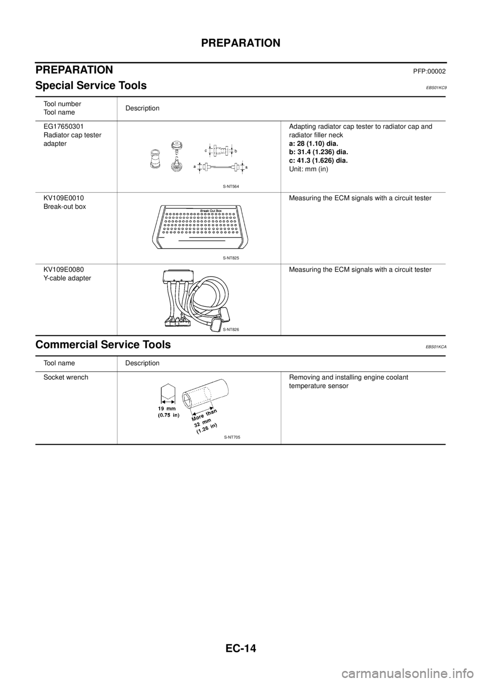
Special Service ToolsEBS01KC9
Commercial Service ToolsEBS01KCA
Tool number
Tool nameDescription
EG17650301
Radiator cap tester
adapterAdapting radiator cap tester to radiator cap and
radiator filler neck
a: 28 (1.10) dia.
b: 31.4 (1.236) dia.
c: 41.3 (1.626) dia.
Unit: mm (in)
KV109E0010
Break-out boxMeasuring the ECM signals with a circuit tester
KV109E0080
Y-cable adapterMeasuring the ECM signals with a circuit tester
S-NT564
S-NT825
S-NT826
Tool name Description
Socket wrench Removing and installing engine coolant
temperature sensor
S-NT705
Page 1003 of 3171
BASIC SERVICE PROCEDURE
EC-23
C
D
E
F
G
H
I
J
K
L
MA
EC
BASIC SERVICE PROCEDUREPFP:00018
Fuel FilterEBS01KCK
DESCRIPTION
A water draining cock is on the lower side and a priming pump for bleeding air is on the upper side.
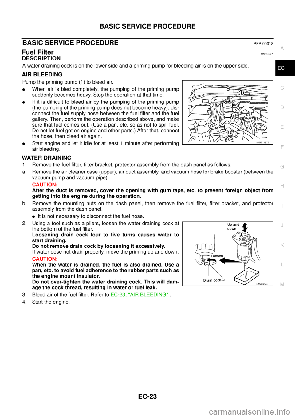
AIR BLEEDING
Pump the priming pump (1) to bleed air.
lWhen air is bled completely, the pumping of the priming pump
suddenly becomes heavy. Stop the operation at that time.
lIf it is difficult to bleed air by the pumping of the priming pump
(the pumping of the priming pump does not become heavy), dis-
connect the fuel supply hose between the fuel filter and the fuel
gallery. Then, perform the operation described above, and make
sure that fuel comes out. (Use a pan, etc. so as not to spill fuel.
Do not let fuel get on engine and other parts.) After that, connect
the hose, then bleed air again.
lStart engine and let it idle for at least 1 minute after performing
air bleeding.
WATER DRAINING
1. Remove the fuel filter, filter bracket, protector assembly from the dash panel as follows.
a. Remove the air cleaner case (upper), air duct assembly, and vacuum hose for brake booster (between the
vacuum pump and vacuum pipe).
CAUTION:
After the duct is removed, cover the opening with gum tape, etc. to prevent foreign object from
getting into the engine during the operation.
b. Remove the mounting nuts on the dash panel, then remove the fuel filter, filter bracket, and protector
assembly from the dash panel.
lIt is not necessary to disconnect the fuel hose.
2. Using a tool such as a pliers, loosen the water draining cock at
the bottom of the fuel filter.
Loosening drain cock four to five turns causes water to
start draining.
Do not remove drain cock by loosening it excessively.
If water dose not drain properly, move the priming up and down.
CAUTION:
When the water is drained, the fuel is also drained. Use a
pan, etc. to avoid fuel adherence to the rubber parts such as
the engine mount insulator.
Do not over-tighten the water draining cock. This will dam-
age the cock thread, resulting in water or fuel leak.
3. Bleed air of the fuel filter. Refer toEC-23, "
AIR BLEEDING".
4. Start the engine.
MBIB1197E
SMA825B
Page 1004 of 3171
EC-24
BASIC SERVICE PROCEDURE
Fuel Pump Learning Value Clearing
EBS01KCL
DESCRIPTION
In order to always keep optimum fuel pressure in fuel rail, the ECM controls fuel pump in high precision with
monitoring the signal of fuel rail pressure sensor.
Accordingly, the ECM always learns characteristic value of fuel pump. Fuel Pump Learning Value Clearing is
an operation to clear the value of the fuel pump learning.
Fuel Pump Learning Value Clearing should be performed under the following conditions.
lFuel pump is changed.
lECM is replaced with used one which stores the fuel pump learning value of other fuel pump.
OPERATION PROCEDURE
NOTE:
When removing fuel pump, perform Fuel Pump Learning Value Clearing before starting engine.
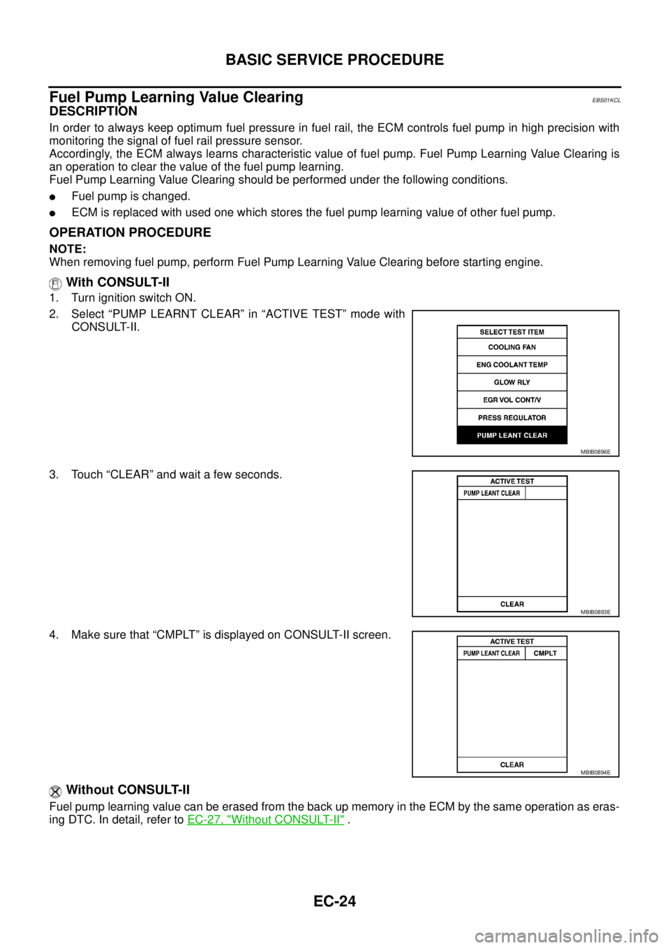
With CONSULT-II
1. Turn ignition switch ON.
2. Select “PUMP LEARNT CLEAR” in “ACTIVE TEST” mode with
CONSULT-II.
3. Touch “CLEAR” and wait a few seconds.
4. Make sure that “CMPLT” is displayed on CONSULT-II screen.
Without CONSULT-II
Fuel pump learning value can be erased from the back up memory in the ECM by the same operation as eras-
ingDTC.Indetail,refertoEC-27, "
Without CONSULT-II".
MBIB0896E
MBIB0893E
MBIB0894E
Page 1005 of 3171
BASIC SERVICE PROCEDURE
EC-25
C
D
E
F
G
H
I
J
K
L
MA
EC
Injector Adjustment Value RegistrationEBS01KCM
DESCRIPTION
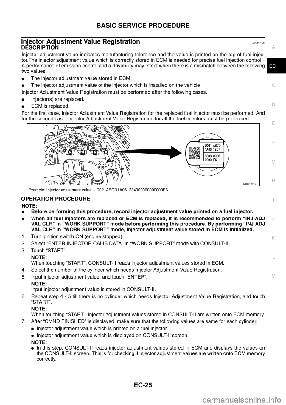
Injector adjustment value indicates manufacturing tolerance and the value is printed on the top of fuel injec-
tor.The injector adjustment value which is correctly stored in ECM is needed for precise fuel injection control.
A performance of emission control and a drivability may effect when there is a mismatch between the following
two values.
lThe injector adjustment value stored in ECM
lThe injector adjustment value of the injector which is installed on the vehicle
Injector Adjustment Value Registration must be performed after the following cases.
lInjector(s) are replaced.
lECM is replaced.
For the first case, Injector Adjustment Value Registration for the replaced fuel injector must be performed. And
for the second case, Injector Adjustment Value Registration for all the fuel injectors must be performed.
OPERATION PROCEDURE
NOTE:
lBefore performing this procedure, record injector adjustment value printed on a fuel injector.
lWhen all fuel injectors are replaced or ECM is replaced, it is recommended to perform “INJ ADJ
VAL CLR” in “WORK SUPPORT” mode before performing this procedure. By performing “INJ ADJ
VAL CLR” in “WORK SUPPORT” mode, injector adjustment value stored in ECM is initialized.
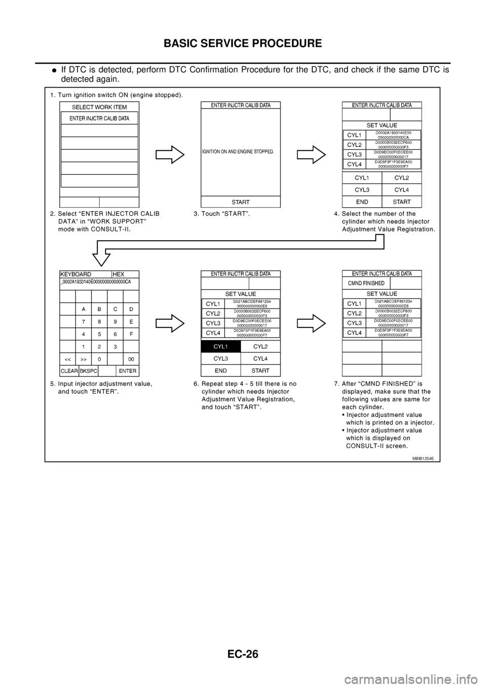
1. Turn ignition switch ON (engine stopped).
2. Select “ENTER INJECTOR CALIB DATA” in “WORK SUPPORT” mode with CONSULT-II.
3. Touch “START”.
NOTE:
When touching “START”, CONSULT-II reads injector adjustment values stored in ECM.
4. Select the number of the cylinder which needs Injector Adjustment Value Registration.
5. Input injector adjustment value, and touch “ENTER”.
NOTE:
Input injector adjustment value is stored in CONSULT-II.
6. Repeat step 4 - 5 till there is no cylinder which needs Injector Adjustment Value Registration, and touch
“START”.
NOTE:
When touching “START”, injector adjustment values stored in CONSULT-II are written onto ECM memory.
7. After “CMND FINISHED” is displayed, make sure that the following values are same for each cylinder.
lInjector adjustment value which is printed on a fuel injector.
lInjector adjustment value which is displayed on CONSULT-II screen.
NOTE:
lIn this step, CONSULT-II reads injector adjustment values stored in ECM and displays the values on
the CONSULT-II screen. This is for checking if injector adjustment values are written onto ECM memory
correctly.
Example: Injector adjustment value = D021ABCD1A061234000000000000E6
MBIB1251E
Page 1006 of 3171
EC-26
BASIC SERVICE PROCEDURE
lIf DTC is detected, perform DTC Confirmation Procedure for the DTC, and check if the same DTC is
detected again.
MBIB1254E