2005 NISSAN NAVARA service
[x] Cancel search: servicePage 884 of 3171

CL-20
SERVICE DATA AND SPECIFICATIONS (SDS)
SERVICE DATA AND SPECIFICATIONS (SDS)
PFP:00030
Clutch Control SystemECS00ICS
Clutch Master CylinderECS00ICT
Clutch Operating CylinderECS00ICU
Clutch DiscECS00ICV
Clutch CoverECS00ICW
Clutch PedalECS00ICX
Type of clutch controlHydraulic
Inner diameter15.87 mm (5/8 in)
Inner diameter19.05 mm (3/4 in)
Facing size (outer dia. x inner dia. x thickness) 240 mm´160 mm´3.15 mm (9.45 in´6.30 in´0.1240 in)
Wear limit of facing surface to rivet head 0.3 mm (0.012 in)
Runout limit/diameter of the area to be measured 1.0 mm (0.039 in) / 230 mm (9.06 in) dia.
Maximum spline backlash (at outer edge of disc) 1.0 mm (0.039 in)
Set-load9,810 N (1,000 kg, 2,205 lb)
Diaphragm spring lever height 39.0 - 41.0 mm (1.535 - 1.614 in)
Uneven limit diaphragm spring toe height 0.7 mm (0.028 in) or less
Clearance²C²between pedal stopper rubber and clutch interlock
switch threaded while clutch pedal is fully depressed0.1 - 1.0 mm (0.004 - 0.039 in)
Page 885 of 3171
CO-1
ENGINE COOLING SYSTEM
B ENGINE
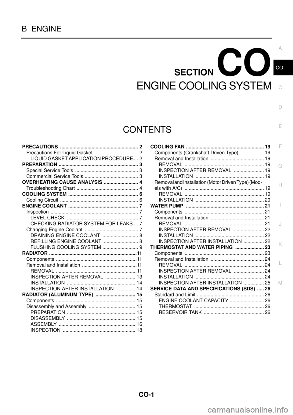
CONTENTS
C
D
E
F
G
H
I
J
K
L
M
SECTIONCO
A
CO
ENGINE COOLING SYSTEM
PRECAUTIONS .......................................................... 2
Precautions For Liquid Gasket ................................. 2
LIQUID GASKET APPLICATION PROCEDURE..... 2
PREPARATION ........................................................... 3
Special Service Tools ............................................... 3
Commercial Service Tools ........................................ 3
OVERHEATING CAUSE ANALYSIS .......................... 4
Troubleshooting Chart .............................................. 4
COOLING SYSTEM .................................................... 6
Cooling Circuit .......................................................... 6
ENGINE COOLANT .................................................... 7
Inspection ................................................................. 7
LEVEL CHECK ..................................................... 7
CHECKING RADIATOR SYSTEM FOR LEAKS..... 7
Changing Engine Coolant ........................................ 7
DRAINING ENGINE COOLANT ........................... 8
REFILLING ENGINE COOLANT .......................... 8
FLUSHING COOLING SYSTEM ........................... 9
RADIATOR .................................................................11
Components ............................................................ 11
Removal and Installation ......................................... 11
REMOVAL ............................................................ 11
INSPECTION AFTER REMOVAL ....................... 13
INSTALLATION ................................................... 14
INSPECTION AFTER INSTALLATION ............... 14
RADIATOR (ALUMINUM TYPE) .............................. 15
Components ........................................................... 15
Disassembly and Assembly ................................... 15
PREPARATION ................................................... 15
DISASSEMBLY ................................................... 15
ASSEMBLY ......................................................... 16
INSPECTION ...................................................... 18COOLING FAN .......................................................... 19
Components (Crankshaft Driven Type) .................. 19
Removal and Installation ........................................ 19
REMOVAL ........................................................... 19
INSPECTION AFTER REMOVAL ....................... 19
INSTALLATION ................................................... 19
Removal and Installation (Motor Driven Type) (Mod-
els with A/C) ........................................................... 19
REMOVAL ........................................................... 19
INSTALLATION ................................................... 20
WATER PUMP .......................................................... 21
Components ........................................................... 21
Removal and Installation ........................................ 21
REMOVAL ........................................................... 21
INSPECTION AFTER REMOVAL ....................... 22
INSTALLATION ................................................... 22
INSPECTION AFTER INSTALLATION ................ 22
THERMOSTAT AND WATER PIPING ...................... 23
Components ........................................................... 23
Removal and Installation ........................................ 24
REMOVAL ........................................................... 24
INSPECTION AFTER REMOVAL ....................... 24
INSTALLATION ................................................... 24
INSPECTION AFTER INSTALLATION ................ 25
SERVICE DATA AND SPECIFICATIONS (SDS) ...... 26
Standard and Limit .................................................. 26
ENGINE COOLANT CAPACITY .......................... 26
THERMOSTAT .................................................... 26
RESERVOIR TANK ............................................. 26
Page 887 of 3171
PREPARATION
CO-3
C
D
E
F
G
H
I
J
K
L
MA
CO
PREPARATIONPFP:00002
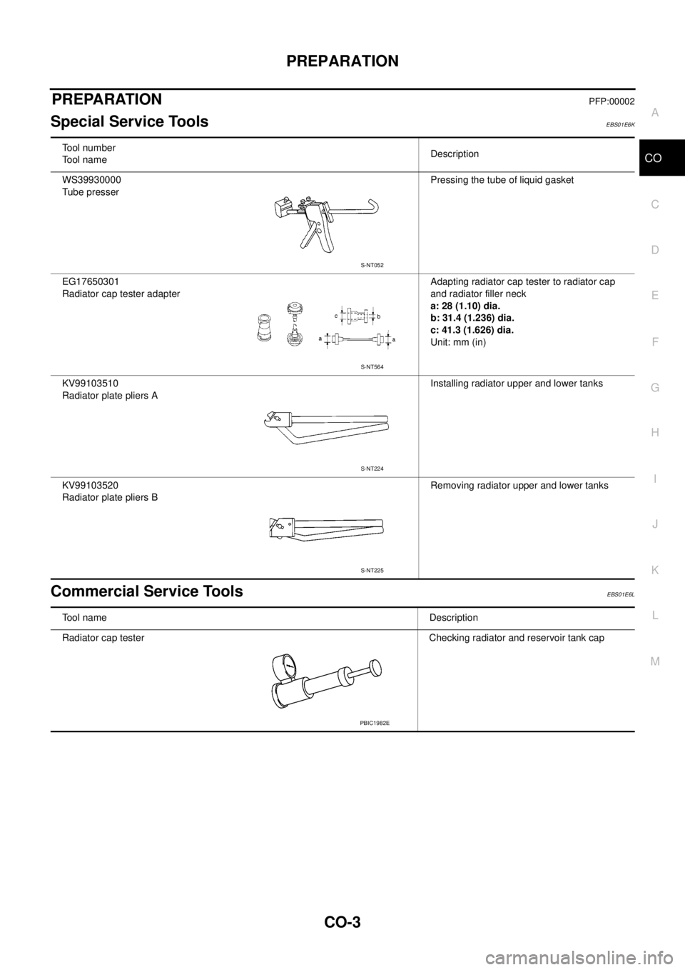
Special Service ToolsEBS01E6K
Commercial Service ToolsEBS01E6L
Tool number
Tool nameDescription
WS39930000
Tube presserPressing the tube of liquid gasket
EG17650301
Radiator cap tester adapterAdapting radiator cap tester to radiator cap
and radiator filler neck
a: 28 (1.10) dia.
b: 31.4 (1.236) dia.
c: 41.3 (1.626) dia.
Unit: mm (in)
KV99103510
Radiator plate pliers AInstalling radiator upper and lower tanks
KV99103520
Radiator plate pliers BRemoving radiator upper and lower tanks
S-NT052
S-NT564
S-NT224
S-NT225
Tool nameDescription
Radiator cap tester Checking radiator and reservoir tank cap
PBIC1982E
Page 891 of 3171
ENGINE COOLANT
CO-7
C
D
E
F
G
H
I
J
K
L
MA
CO
ENGINE COOLANTPFP:KQ100
InspectionEBS01E6P
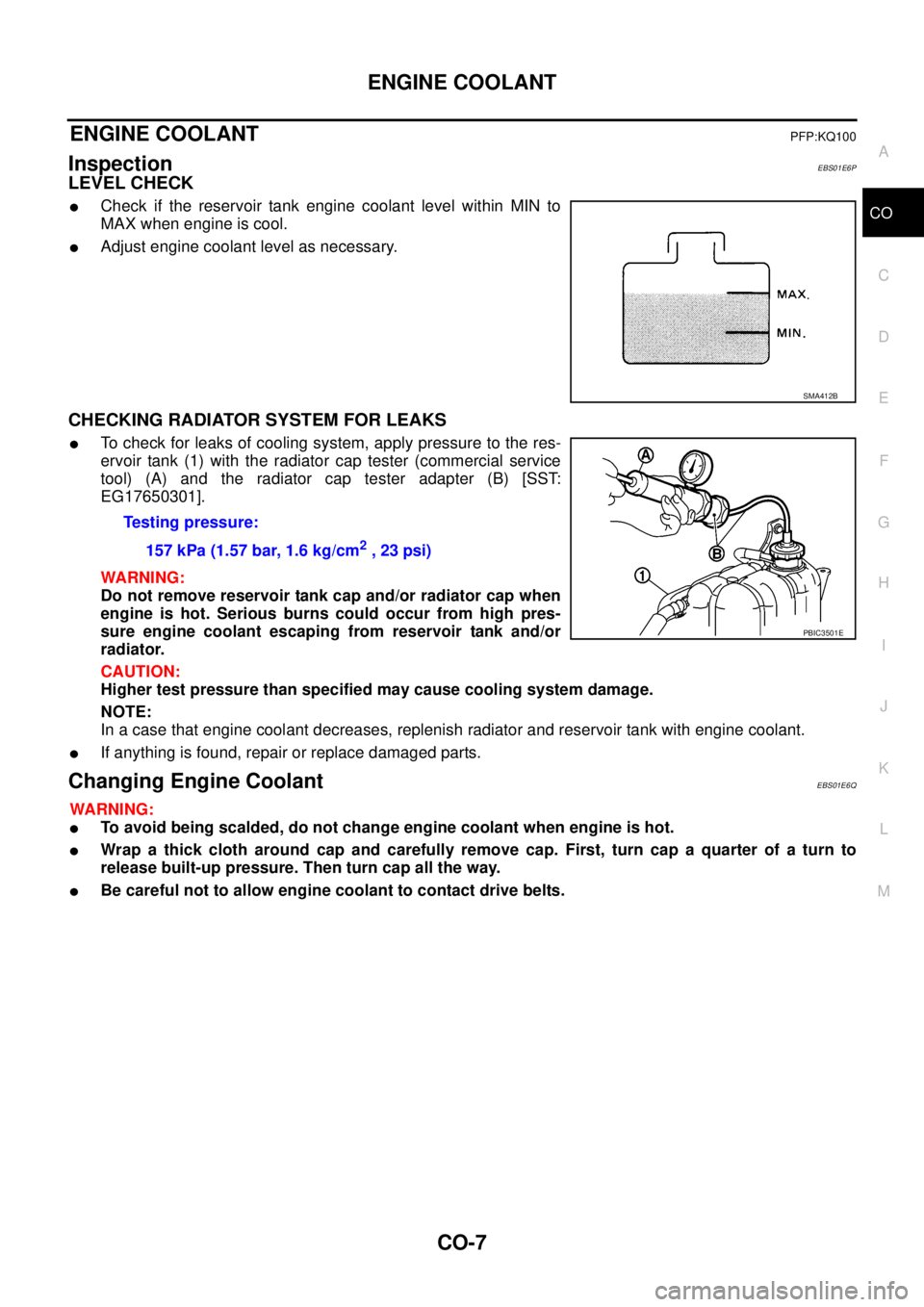
LEVEL CHECK
lCheck if the reservoir tank engine coolant level within MIN to
MAX when engine is cool.
lAdjust engine coolant level as necessary.
CHECKING RADIATOR SYSTEM FOR LEAKS
lTo check for leaks of cooling system, apply pressure to the res-
ervoir tank (1) with the radiator cap tester (commercial service
tool) (A) and the radiator cap tester adapter (B) [SST:
EG17650301].
WARNING:
Do not remove reservoir tank cap and/or radiator cap when
engine is hot. Serious burns could occur from high pres-
sure engine coolant escaping from reservoir tank and/or
radiator.
CAUTION:
Higher test pressure than specified may cause cooling system damage.
NOTE:
In a case that engine coolant decreases, replenish radiator and reservoir tank with engine coolant.
lIf anything is found, repair or replace damaged parts.
Changing Engine CoolantEBS01E6Q
WARNING:
lTo avoid being scalded, do not change engine coolant when engine is hot.
lWrap a thick cloth around cap and carefully remove cap. First, turn cap a quarter of a turn to
release built-up pressure. Then turn cap all the way.
lBe careful not to allow engine coolant to contact drive belts.
SMA412B
Testing pressure:
157 kPa (1.57 bar, 1.6 kg/cm
2,23psi)
PBIC3501E
Page 897 of 3171
RADIATOR
CO-13
C
D
E
F
G
H
I
J
K
L
MA
CO
INSPECTION AFTER REMOVAL
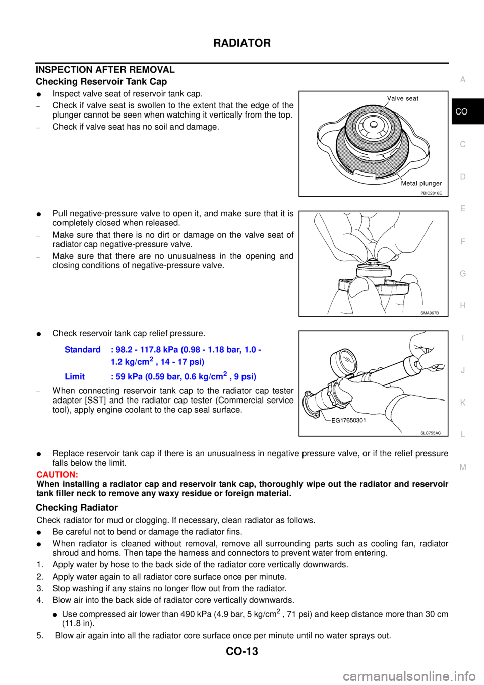
Checking Reservoir Tank Cap
lInspect valve seat of reservoir tank cap.
–Check if valve seat is swollen to the extent that the edge of the
plunger cannot be seen when watching it vertically from the top.
–Check if valve seat has no soil and damage.
lPull negative-pressure valve to open it, and make sure that it is
completely closed when released.
–Make sure that there is no dirt or damage on the valve seat of
radiator cap negative-pressure valve.
–Make sure that there are no unusualness in the opening and
closing conditions of negative-pressure valve.
lCheck reservoir tank cap relief pressure.
–When connecting reservoir tank cap to the radiator cap tester
adapter [SST] and the radiator cap tester (Commercial service
tool), apply engine coolant to the cap seal surface.
lReplace reservoir tank cap if there is an unusualness in negative pressure valve, or if the relief pressure
falls below the limit.
CAUTION:
When installing a radiator cap and reservoir tank cap, thoroughly wipe out the radiator and reservoir
tank filler neck to remove any waxy residue or foreign material.
Checking Radiator
Check radiator for mud or clogging. If necessary, clean radiator as follows.
lBe careful not to bend or damage the radiator fins.
lWhen radiator is cleaned without removal, remove all surrounding parts such as cooling fan, radiator
shroud and horns. Then tape the harness and connectors to prevent water from entering.
1. Apply water by hose to the back side of the radiator core vertically downwards.
2. Apply water again to all radiator core surface once per minute.
3. Stop washing if any stains no longer flow out from the radiator.
4. Blow air into the back side of radiator core vertically downwards.
lUse compressed air lower than 490 kPa (4.9 bar, 5 kg/cm2, 71 psi) and keep distance more than 30 cm
(11.8 in).
5. Blow air again into all the radiator core surface once per minute until no water sprays out.
PBIC2816E
SMA967B
Standard : 98.2 - 117.8 kPa (0.98 - 1.18 bar, 1.0 -
1.2 kg/cm
2,14-17psi)
Limit : 59 kPa (0.59 bar, 0.6 kg/cm
2,9psi)
SLC755AC
Page 898 of 3171
![NISSAN NAVARA 2005 Repair Workshop Manual CO-14
RADIATOR
INSTALLATION
Installation is the reverse order of removal.
INSPECTION AFTER INSTALLATION
lCheck for leaks of engine coolant using the radiator cap tester adapter [SST: EG17650301] and t NISSAN NAVARA 2005 Repair Workshop Manual CO-14
RADIATOR
INSTALLATION
Installation is the reverse order of removal.
INSPECTION AFTER INSTALLATION
lCheck for leaks of engine coolant using the radiator cap tester adapter [SST: EG17650301] and t](/manual-img/5/57362/w960_57362-897.png)
CO-14
RADIATOR
INSTALLATION
Installation is the reverse order of removal.
INSPECTION AFTER INSTALLATION
lCheck for leaks of engine coolant using the radiator cap tester adapter [SST: EG17650301] and the radia-
tor cap tester (commercial service tool). Refer toCO-7, "
CHECKING RADIATOR SYSTEM FOR LEAKS".
lStart and warm up engine. Visually check if there is no leaks of engine coolant.
Page 902 of 3171
![NISSAN NAVARA 2005 Repair Workshop Manual CO-18
RADIATOR (ALUMINUM TYPE)
5. Make sure that there is no leakage.
Refer toCO-18, "
INSPECTION".
INSPECTION
1. Apply pressure with the radiator cap tester adapter [SST] and
the radiator cap tester NISSAN NAVARA 2005 Repair Workshop Manual CO-18
RADIATOR (ALUMINUM TYPE)
5. Make sure that there is no leakage.
Refer toCO-18, "
INSPECTION".
INSPECTION
1. Apply pressure with the radiator cap tester adapter [SST] and
the radiator cap tester](/manual-img/5/57362/w960_57362-901.png)
CO-18
RADIATOR (ALUMINUM TYPE)
5. Make sure that there is no leakage.
Refer toCO-18, "
INSPECTION".
INSPECTION
1. Apply pressure with the radiator cap tester adapter [SST] and
the radiator cap tester (commercial service tool).
WARNING:
To prevent the risk of hose coming undone while under
pressure, securely fasten it down with hose clamp.
CAUTION:
Attach hose to A/T fluid cooler to seal its inlet and outlet. (A/
T models)
2. Check for leakage by soaking radiator in water container with
the testing pressure applied.Testing pressure
: 157 kPa (1.57 bar, 1.6 kg/cm
2,23psi)
SLC933
SLC934
Page 905 of 3171
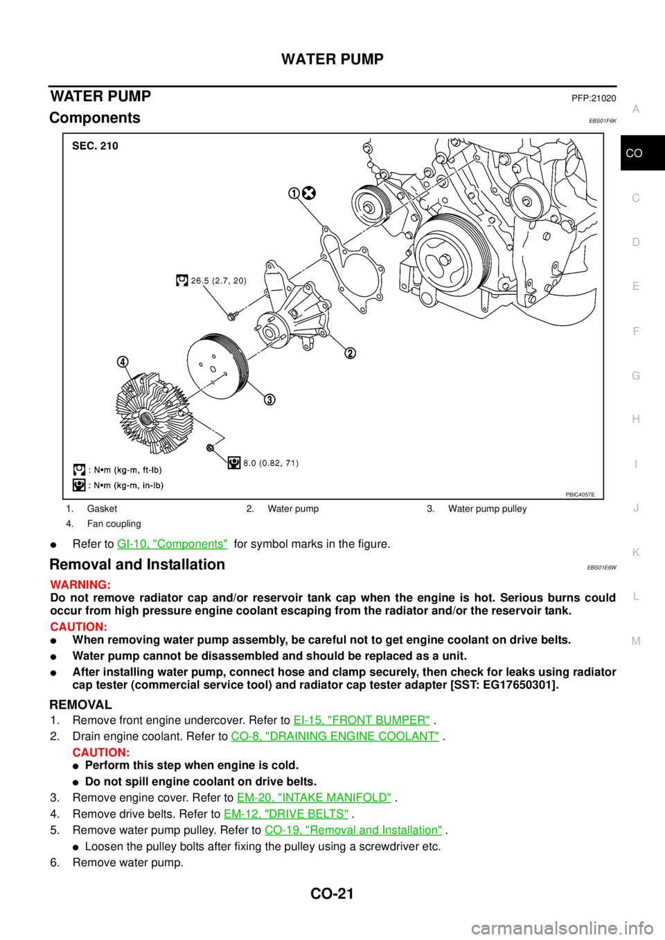
WATER PUMP
CO-21
C
D
E
F
G
H
I
J
K
L
MA
CO
WAT E R P U MPPFP:21020
ComponentsEBS01F6K
lRefer toGI-10, "Components"for symbol marks in the figure.
Removal and InstallationEBS01E6W
WARNING:
Do not remove radiator cap and/or reservoir tank cap when the engine is hot. Serious burns could
occur from high pressure engine coolant escaping from the radiator and/or the reservoir tank.
CAUTION:
lWhen removing water pump assembly, be careful not to get engine coolant on drive belts.
lWater pump cannot be disassembled and should be replaced as a unit.
lAfter installing water pump, connect hose and clamp securely, then check for leaks using radiator
cap tester (commercial service tool) and radiator cap tester adapter [SST: EG17650301].
REMOVAL
1. Remove front engine undercover. Refer toEI-15, "FRONT BUMPER".
2. Drain engine coolant. Refer toCO-8, "
DRAINING ENGINE COOLANT".
CAUTION:
lPerform this step when engine is cold.
lDo not spill engine coolant on drive belts.
3. Remove engine cover. Refer toEM-20, "
INTAKE MANIFOLD".
4. Remove drive belts. Refer toEM-12, "
DRIVE BELTS".
5. Remove water pump pulley. Refer toCO-19, "
Removal and Installation".
lLoosen the pulley bolts after fixing the pulley using a screwdriver etc.
6. Remove water pump.
1. Gasket 2. Water pump 3. Water pump pulley
4. Fan coupling
PBIC4057E