Page 906 of 3171
CO-22
WATER PUMP
lEngine coolant will leak from cylinder block, so have a receptacle ready below.
CAUTION:
lHandle the water pump vane so that it does not contact any other parts.
lWater pump cannot be disassembled and should be replaced as a unit.
INSPECTION AFTER REMOVAL
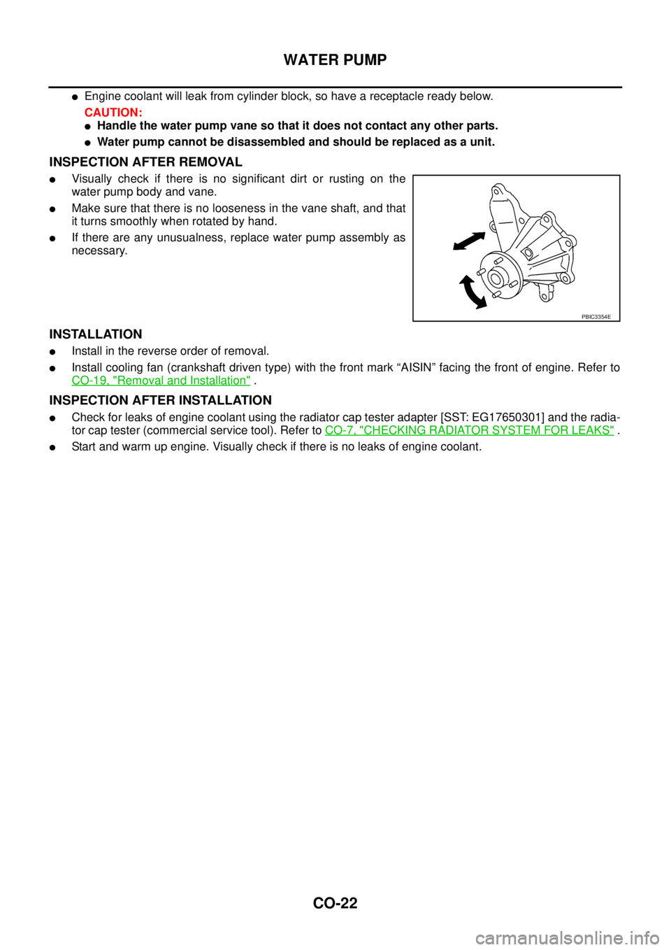
lVisually check if there is no significant dirt or rusting on the
water pump body and vane.
lMake sure that there is no looseness in the vane shaft, and that
it turns smoothly when rotated by hand.
lIf there are any unusualness, replace water pump assembly as
necessary.
INSTALLATION
lInstall in the reverse order of removal.
lInstall cooling fan (crankshaft driven type) with the front mark “AISIN” facing the front of engine. Refer to
CO-19, "
Removal and Installation".
INSPECTION AFTER INSTALLATION
lCheck for leaks of engine coolant using the radiator cap tester adapter [SST: EG17650301] and the radia-
tor cap tester (commercial service tool). Refer toCO-7, "
CHECKING RADIATOR SYSTEM FOR LEAKS".
lStart and warm up engine. Visually check if there is no leaks of engine coolant.
PBIC3354E
Page 909 of 3171
THERMOSTAT AND WATER PIPING
CO-25
C
D
E
F
G
H
I
J
K
L
MA
CO
lInstall the thermostat with the whole circumference of each
flange part fit securely inside the rubber ring.
lInstall the thermostat with the jiggle valve facing upwards.
INSPECTION AFTER INSTALLATION
lCheck for leaks of engine coolant using the radiator cap tester adapter [SST: EG17650301] and the radia-
tor cap tester (commercial service tool). Refer toCO-7, "
CHECKING RADIATOR SYSTEM FOR LEAKS".
lStart and warm up engine. Visually check if there is no leaks of engine coolant.
JLC300B
Page 910 of 3171
CO-26
SERVICE DATA AND SPECIFICATIONS (SDS)
SERVICE DATA AND SPECIFICATIONS (SDS)
PFP:00030
Standard and LimitEBS01E6Y
ENGINE COOLANT CAPACITY
Unit: (lmp qt)
THERMOSTAT
RESERVOIR TANK
Unit:kPa(bar,kg/cm2, psi)
Engine coolant capacity
(With reservoir tank at “MAX” level)LHD models Approx. 9.9 (8-3/4)
RHD models Approx. 10.2 (9)
Reservoir tank (at “MAX” level)0.8 (3/4)
Valve opening temperature 80.5 - 83.5°C (177 - 182°F)
Full open lift amount More than 9 mm/ 95°C (0.35 in/203°F)
Valve closing temperature More than 77°C(171°F)
Cap relief pressureStandard 98.2 - 117.8 (0.98 - 1.18, 1.0 - 1.2, 14 - 17)
Limit 59 (0.59, 0.6, 9)
Leakage test pressure 157 (1.57, 1.6, 23)
Page 913 of 3171
PRECAUTION
DI-3
C
D
E
F
G
H
I
J
L
MA
B
DI
PRECAUTIONPFP:00011
Precautions for Supplemental Restraint System (SRS) “AIR BAG” and “SEAT
BELT PRE-TENSIONER”
EKS00N1V
The Supplemental Restraint System such as “AIR BAG” and “SEAT BELT PRE-TENSIONER”, used along
with a front seat belt, helps to reduce the risk or severity of injury to the driver and front passenger for certain
types of collision. Information necessary to service the system safely is included in the SRS and SB section of
this Service Manual.
WARNING:
lTo avoid rendering the SRS inoperative, which could increase the risk of personal injury or death
in the event of a collision which would result in air bag inflation, all maintenance must be per-
formed by an authorized NISSAN/INFINITI dealer.
lImproper maintenance, including incorrect removal and installation of the SRS, can lead to per-
sonal injury caused by unintentional activation of the system. For removal of Spiral Cable and Air
Bag Module, see the SRS section.
lDo not use electrical test equipment on any circuit related to the SRS unless instructed to in this
Service Manual. SRS wiring harnesses can be identified by yellow and/or orange harnesses or
harness connectors.
Wiring Diagrams and Trouble DiagnosisEKS00L8C
When reading wiring diagrams, refer to the following:
lGI-15, "How to Read Wiring Diagrams"
lPG-4, "POWER SUPPLY ROUTING CIRCUIT"for power distribution circuit
When performing trouble diagnosis, refer to the following:
lGI-11, "HOW TO FOLLOW TEST GROUPS IN TROUBLE DIAGNOSES"
lGI-24, "How to Perform Efficient Diagnosis for an Electrical Incident"
Page 923 of 3171
COMBINATION METERS
DI-13
C
D
E
F
G
H
I
J
L
MA
B
DI
Self-Diagnosis Mode of Combination MeterEKS00L8K
FUNCTION
The following items can be checked during self-diagnosis mode.
lSweep of gauges pointer
lPresent gauge data values
lOdo/trip meter display and clock display segments
lCondition of warning lamps/indicator lamps controlled by unified meter control unit
lBattery voltage
lDriver's seat belt buckle switch status
lCPU of unified meter control unit status
OPERATION PROCEDURE
To initiate combination meter self-diagnosis mode, refer to the following procedure.
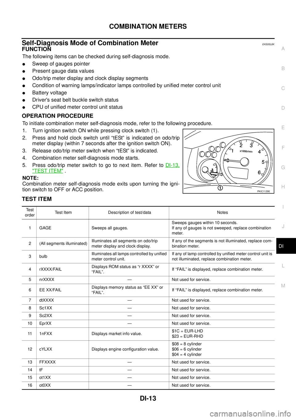
1. Turn ignition switch ON while pressing clock switch (1).
2. Press and hold clock switch until “tESt” is indicated on odo/trip
meter display (within 7 seconds after the ignition switch ON).
3. Release odo/trip meter switch when “tESt” is indicated.
4. Combination meter self-diagnosis mode starts.
5. Pressodo/tripmeterswitchtogotonextitem.RefertoDI-13,
"TEST ITEM".
NOTE:
Combination meter self-diagnosis mode exits upon turning the igni-
tion switch to OFF or ACC position.
TEST ITEM
PKIC1129E
Te s t
orderTest Item Description of test/data Notes
1 GAGE Sweeps all gauges.Sweeps gauges within 10 seconds.
If any of gauges is not sweeped, replace combination
meter.
2 (All segments illuminated)Illuminates all segments on odo/trip
meter display and clock display.If any of the segments is not illuminated, replace com-
bination meter.
3 bulbIlluminates all lamps controlled by unified
meter control unit.If any of lamp controlled by unified meter control unit is
not illuminated, replace combination meter.
4 rXXXX/FAILDisplays ROM status as “r XXXX” or
“FAIL”.If “FAIL” is displayed, replace combination meter.
5 nrXXXX — Not used for service.
6 EE XX/FAILDisplays memory status as “EE XX” or
“FAIL”.If “FAIL” is displayed, replace combination meter.
7 dtXXXX — Not used for service.
8 Sc1XX — Not used for service.
9 Sc2XX — Not used for service.
10 EprXX — Not used for service.
11 1nFXX Displays market info value.$1C = EUR-LHD
$23 = EUR-RHD
12 cYLXX Displays engine configuration value.$08 = 8 cylinder
$06 = 6 cylinder
$04 = 4 cylinder
13 FFXXXX — Not used for service.
14 tF — Not used for service.
15 ot1XX — Not used for service.
16 ot0XX — Not used for service.
Page 924 of 3171
DI-14
COMBINATION METERS
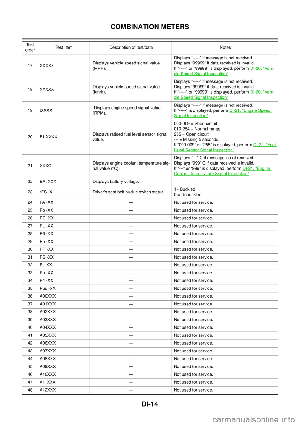
17 XXXXXDisplays vehicle speed signal value
(MPH).Displays “-----” if message is not received.
Displays “99999” if data received is invalid.
If “-----” or “99999” is displayed, performDI-20, "Ve h i-
cle Speed Signal Inspection".
18 XXXXXDisplays vehicle speed signal value
(km/h).Displays “-----” if message is not received.
Displays “99999” if data received is invalid.
If “-----” or “99999” is displayed, performDI-20, "
Ve h i-
cle Speed Signal Inspection".
19 tXXXXDisplays engine speed signal value
(RPM).Displays “-----” if message is not received.
If “-----” is displayed, performDI-21, "
Engine Speed
Signal Inspection".
20 F1 XXXXDisplays ratioed fuel level sensor signal
value.000-009 = Short circuit
010-254 = Normal range
255 = Open circuit
--- = Missing 5 seconds
If “000-009” or “255” is displayed, performDI-22, "
Fuel
Level Sensor Signal Inspection".
21 XXXCDisplays engine coolant temperature sig-
nal value (°C).Displays “---” C if message is not received.
Displays “999” C if data received is invalid.
If “---” or “999” is displayed, performDI-21, "
Engine
Coolant Temperature Signal Inspection".
22 BAt XXX Displays battery voltage.
23 rES -X Driver's seat belt buckle switch status.1= Buckled
0 = Unbuckled
24 PA -XX — Not used for service.
25 Pb -XX — Not used for service.
26 PE -XX — Not used for service.
27 PL -XX — Not used for service.
28 P6 -XX — Not used for service.
29 Pn -XX — Not used for service.
30 PP -XX — Not used for service.
31 PS -XX — Not used for service.
32 Pt -XX — Not used for service.
33 Pu -XX — Not used for service.
34 P4 -XX — Not used for service.
35 Puu -XX — Not used for service.
36 A00XXX — Not used for service.
37 A01XXX — Not used for service.
38 A02XXX — Not used for service.
39 A03XXX — Not used for service.
40 A04XXX — Not used for service.
41 A05XXX — Not used for service.
42 A06XXX — Not used for service.
43 A07XXX — Not used for service.
44 A08XXX — Not used for service.
45 A09XXX — Not used for service.
46 A10XXX — Not used for service.
47 A11XXX — Not used for service.
48 A12XXX — Not used for service. Te s t
orderTest Item Description of test/data Notes
Page 925 of 3171
COMBINATION METERS
DI-15
C
D
E
F
G
H
I
J
L
MA
B
DI
CONSULT-II Function (METER)EKS00L8L
CONSULT-II can display each diagnostic item using the diagnostic test modes shown following.
NOTE:
This item is not available though indicated.
CONSULT-II BASIC OPERATION
CAUTION:
If CONSULT-II is used with no connection of CONSULT-II CONVERTER, malfunctions might be
detected in self-diagnosis depending on control unit which carry out CAN communication.
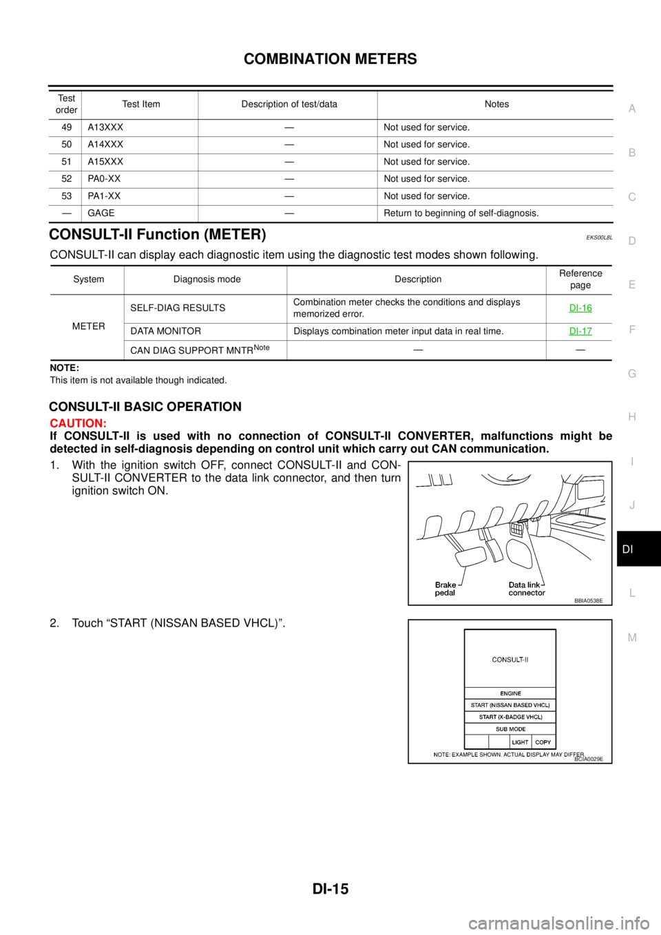
1. With the ignition switch OFF, connect CONSULT-II and CON-
SULT-II CONVERTER to the data link connector, and then turn
ignition switch ON.
2. Touch “START (NISSAN BASED VHCL)”.
49 A13XXX — Not used for service.
50 A14XXX — Not used for service.
51 A15XXX — Not used for service.
52 PA0-XX — Not used for service.
53 PA1-XX — Not used for service.
— GAGE — Return to beginning of self-diagnosis. Te s t
orderTest Item Description of test/data Notes
System Diagnosis mode DescriptionReference
page
METERSELF-DIAG RESULTSCombination meter checks the conditions and displays
memorized error.DI-16
DATA MONITOR Displays combination meter input data in real time.DI-17
CAN DIAG SUPPORT MNTRNote——
BBIA0538E
BCIA0029E
Page 971 of 3171
WARNING CHIME
DI-61
C
D
E
F
G
H
I
J
L
MA
B
DI
SYMPTOM CHART
Meter Buzzer Circuit InspectionEKS00L9L
1.CHECK CHIME OPERATION
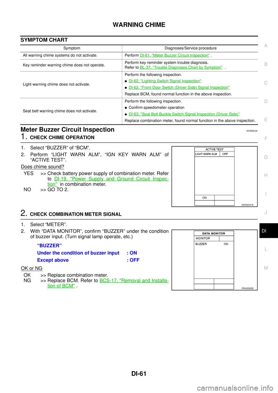
1. Select “BUZZER” of “BCM”.
2. Perform “LIGHT WARN ALM”, “IGN KEY WARN ALM” of
“ACTIVE TEST”.
Does chime sound?
YES >> Check battery power supply of combination meter. Refer
toDI-19, "
Power Supply and Ground Circuit Inspec-
tion"in combination meter.
NO >> GO TO 2.
2.CHECK COMBINATION METER SIGNAL
1. Select “METER”.
2. With “DATA MONITOR”, confirm “BUZZER” under the condition
of buzzer input. (Turn signal lamp operate, etc.)
OK or NG
OK >> Replace combination meter.
NG >> Replace BCM. Refer toBCS-17, "
Removal and Installa-
tion of BCM".
Symptom Diagnoses/Service procedure
All warning chime systems do not activate. PerformDI-61, "
Meter Buzzer Circuit Inspection".
Key reminder warning chime does not operate.Perform key reminder system trouble diagnosis.
Refer toBL-37, "
Trouble Diagnoses Chart by Symptom".
Light warning chime does not activate.Perform the following inspection.
lDI-62, "Lighting Switch Signal Inspection"
lDI-62, "Front Door Switch (Driver Side) Signal Inspection"
Replace BCM, found normal function in the above inspection.
Seat belt warning chime does not activate.Perform the following inspection.
lConfirm speedometer operation
lDI-63, "Seat Belt Buckle Switch Signal Inspection (Driver Side)"
Replace combination meter, found normal function in the above inspection.
SKIA6331E
“BUZZER”
Under the condition of buzzer input : ON
Except above : OFF
PKIA2063E