2005 NISSAN NAVARA service
[x] Cancel search: servicePage 759 of 3171
NATS(NISSAN ANTI-THEFT SYSTEM)
BL-175
C
D
E
F
G
H
J
K
L
MA
B
BL
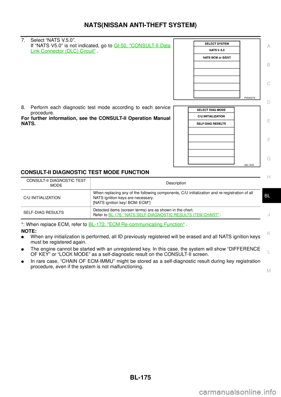
7. Select “NATS V.5.0”.
If “NATS V5.0” is not indicated, go toGI-50, "
CONSULT-II Data
Link Connector (DLC) Circuit".
8. Perform each diagnostic test mode according to each service
procedure.
For further information, see the CONSULT-II Operation Manual
NATS.
CONSULT-II DIAGNOSTIC TEST MODE FUNCTION
*: When replace ECM, refer toBL-172, "ECM Re-communicating Function".
NOTE:
lWhen any initialization is performed, all ID previously registered will be erased and all NATS ignition keys
must be registered again.
lThe engine cannot be started with an unregistered key. In this case, the system will show “DIFFERENCE
OF KEY” or “LOCK MODE” as a self-diagnostic result on the CONSULT-II screen.
lIn rare case, “CHAIN OF ECM-IMMU” might be stored as a self-diagnostic result during key registration
procedure, even if the system is not malfunctioning.
PIIA9327E
SEL150X
CONSULT-II DIAGNOSTIC TEST
MODEDescription
C/U INITIALIZATIONWhen replacing any of the following components, C/U initialization and re-registration of all
NATS ignition keys are necessary.
[NATS ignition key/ BCM/ ECM*]
SELF-DIAG RESULTSDetected items (screen terms) are as shown in the chart.
Refer toBL-176, "
NATS SELF-DIAGNOSTIC RESULTS ITEM CHART".
Page 787 of 3171

BR-1
BRAKE SYSTEM
F BRAKES
CONTENTS
C
D
E
G
H
I
J
K
L
M
SECTIONBR
A
B
BR
BRAKE SYSTEM
PRECAUTIONS .......................................................... 3
Precautions for Supplemental Restraint System
(SRS)“AIRBAG”and“SEATBELTPRE-TEN-
SIONER” .................................................................. 3
Precautions for Brake System .................................. 3
PREPARATION ........................................................... 4
Special Service Tools ............................................... 4
Commercial Service Tools ........................................ 4
NOISE, VIBRATION AND HARSHNESS (NVH)
TROUBLESHOOTING ................................................ 5
NVH Troubleshooting Chart ..................................... 5
BRAKE PEDAL .......................................................... 6
Inspection and Adjustment ....................................... 6
ADJUSTMENT ...................................................... 7
Removal and Installation .......................................... 8
COMPONENTS .................................................... 8
REMOVAL ............................................................. 8
INSPECTION AFTER REMOVAL ......................... 9
INSTALLATION ..................................................... 9
BRAKE FLUID .......................................................... 10
On-board Inspection ............................................... 10
CHECKING BRAKE FLUID LEVEL .................... 10
Drain and Refill ....................................................... 10
Bleeding Brake System ........................................... 11
LHD MODEL ........................................................ 11
RHD MODEL ........................................................ 11
BRAKE TUBE AND HOSE ....................................... 12
Hydraulic Circuit ..................................................... 12
Removal and Installation of Front Brake Tube and
Brake Hose ............................................................ 13
REMOVAL ........................................................... 13
INSTALLATION ................................................... 13
Removal and Installation of Rear Brake Tube and
Brake Hose ............................................................ 13
REMOVAL ........................................................... 13
INSTALLATION ................................................... 13
Inspection after Installation .................................... 14
LOAD SENSING VALVE .......................................... 15
Removal and Installation ........................................ 15
REMOVAL ........................................................... 15INSTALLATION ................................................... 15
Inspection ............................................................... 16
INSPECTION ...................................................... 16
BRAKE MASTER CYLINDER .................................. 17
On-Board Inspection ............................................... 17
LEAK INSPECTION ............................................ 17
Removal and Installation ........................................ 17
REMOVAL ........................................................... 17
INSTALLATION ................................................... 17
Components ........................................................... 17
Disassembly and Assembly .................................... 18
DISASSEMBLY ................................................... 18
ASSEMBLY ......................................................... 18
BRAKE BOOSTER ................................................... 19
On-Vehicle Service ................................................. 19
OPERATING CHECK .......................................... 19
AIRTIGHT CHECK .............................................. 19
Removal and Installation ........................................ 20
COMPONENTS ................................................... 20
REMOVAL ........................................................... 20
INSPECTION AFTER REMOVAL ....................... 20
INSTALLATION ................................................... 21
VACUUM LINES ....................................................... 22
Component ............................................................. 22
Removal and Installation ........................................ 23
Inspection ............................................................... 23
VISUAL INSPECTION ......................................... 23
CHECK VALVE INSPECTION ............................. 23
FRONT DISC BRAKE ............................................... 24
On-Board Inspection ............................................... 24
PAD WEAR INSPECTION ................................... 24
Components ........................................................... 24
Removal and Installation of Brake Pad .................. 25
REMOVAL ........................................................... 25
INSTALLATION ................................................... 25
Removal and Installation of Brake Caliper Assembly
... 26
REMOVAL ........................................................... 26
INSTALLATION ................................................... 26
Disassembly and Assembly of Brake Caliper
Page 788 of 3171

BR-2
Assembly ................................................................ 26
DISASSEMBLY ................................................... 26
INSPECTION AFTER DISASSEMBLY ................ 27
ASSEMBLY ......................................................... 28
DISC ROTOR INSPECTION ............................... 28
BRAKE BURNISHING PROCEDURE ................. 29
REAR DRUM BRAKE ............................................... 30
Components ........................................................... 30
Removal and Installation of Drum Brake Assembly... 31
REMOVAL ........................................................... 31
INSPECTION AFTER REMOVAL ........................ 32
INSTALLATION .................................................... 33
Removal and Installation of Wheel Cylinder ........... 34REMOVAL ............................................................ 34
INSTALLATION .................................................... 34
Disassembly and Assembly of Wheel Cylinder ....... 34
DISASSEMBLY .................................................... 34
INSPECTION AFTER DISASSEMBLY ................ 34
ASSEMBLY .......................................................... 34
SERVICE DATA AND SPECIFICATIONS (SDS) ...... 35
General Specifications ............................................ 35
Brake Pedal ............................................................ 35
Brake Booster ......................................................... 35
Check Valve ............................................................ 35
Front Disc Brake ..................................................... 35
Rear Disc Brake ...................................................... 36
Page 789 of 3171
PRECAUTIONS
BR-3
C
D
E
G
H
I
J
K
L
MA
B
BR
PRECAUTIONSPFP:00001
Precautions for Supplemental Restraint System (SRS) “AIR BAG” and “SEAT
BELT PRE-TENSIONER”
EFS006DL
The Supplemental Restraint System such as “AIR BAG” and “SEAT BELT PRE-TENSIONER”, used along
with a front seat belt, helps to reduce the risk or severity of injury to the driver and front passenger for certain
types of collision. Information necessary to service the system safely is included in the SRS and SB section of
this Service Manual.
WARNING:
lTo avoid rendering the SRS inoperative, which could increase the risk of personal injury or death
in the event of a collision which would result in air bag inflation, all maintenance must be per-
formed by an authorized NISSAN/INFINITI dealer.
lImproper maintenance, including incorrect removal and installation of the SRS, can lead to per-
sonal injury caused by unintentional activation of the system. For removal of Spiral Cable and Air
Bag Module, see the SRS section.
lDo not use electrical test equipment on any circuit related to the SRS unless instructed to in this
Service Manual. SRS wiring harnesses can be identified by yellow and/or orange harnesses or
harness connectors.
Precautions for Brake SystemEFS005SD
lClean dust on front brake and rear brake with a vacuum dust collector. Do not blow with compressed air.
lRecommended fluid is brake fluid “DOT 3” or “DOT 4”.
lNever reuse drained brake fluid.
lBe careful not to splash brake fluid on painted areas; it may cause paint damage. If brake fluid is splashed
on painted areas, wash it away with water immediately.
lTo clean or wash all parts of master cylinder, disc brake caliper, wheel cylinder, use new brake fluid.
lNever use mineral oils such as gasoline or kerosene. They will ruin rubber parts of the hydraulic system.
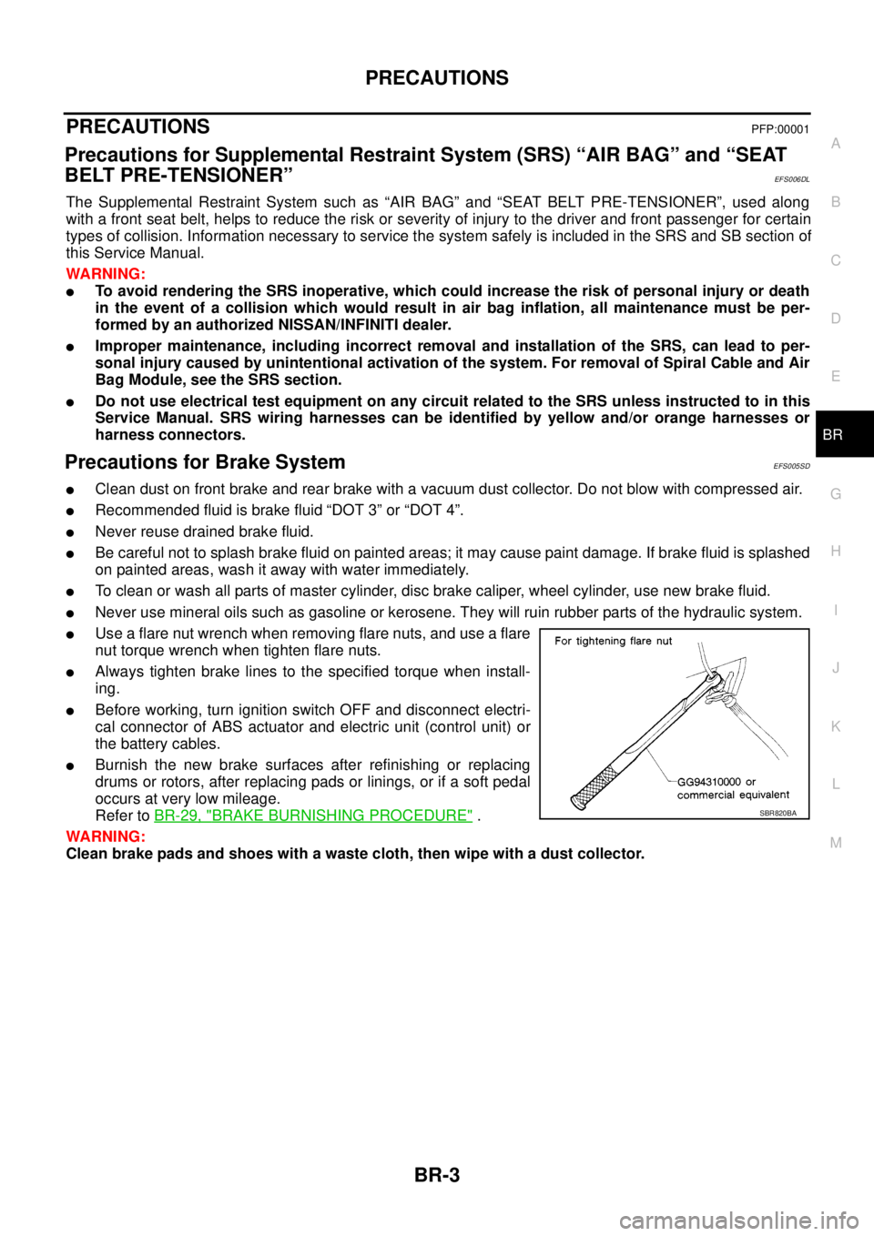
lUse a flare nut wrench when removing flare nuts, and use a flare
nut torque wrench when tighten flare nuts.
lAlways tighten brake lines to the specified torque when install-
ing.
lBefore working, turn ignition switch OFF and disconnect electri-
cal connector of ABS actuator and electric unit (control unit) or
the battery cables.
lBurnish the new brake surfaces after refinishing or replacing
drums or rotors, after replacing pads or linings, or if a soft pedal
occurs at very low mileage.
Refer toBR-29, "
BRAKE BURNISHING PROCEDURE".
WARNING:
Clean brake pads and shoes with a waste cloth, then wipe with a dust collector.SBR820BA
Page 790 of 3171
BR-4
PREPARATION
PREPARATION
PFP:00002
Special Service ToolsEFS005SE
Commercial Service ToolsEFS005TE
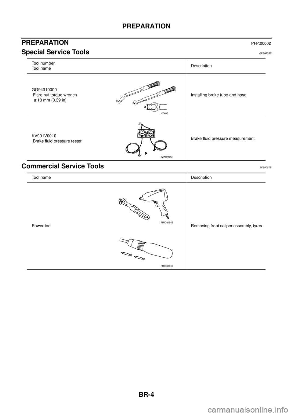
Tool number
Tool nameDescription
GG94310000
Flare nut torque wrench
a:10 mm (0.39 in)Installing brake tube and hose
KV991V0010
Brake fluid pressure testerBrake fluid pressure measurement
NT406
ZZA0752D
Tool nameDescription
Power toolRemoving front caliper assembly, tyres
PBIC0190E
PBIC0191E
Page 802 of 3171
BR-16
LOAD SENSING VALVE
Inspection
EFS006A8
INSPECTION
1. With the vehicle in unladen condition, a person should sit in driver's seat at the rear. Then he/she should
get out of car gently. (This is to stabilize suspension deflection.)
NOTE:
“Unladen condition”: with full coolant, lubricant, 6 to 8 litters of fuel, spare tyre, jack, and hand tools
loaded.
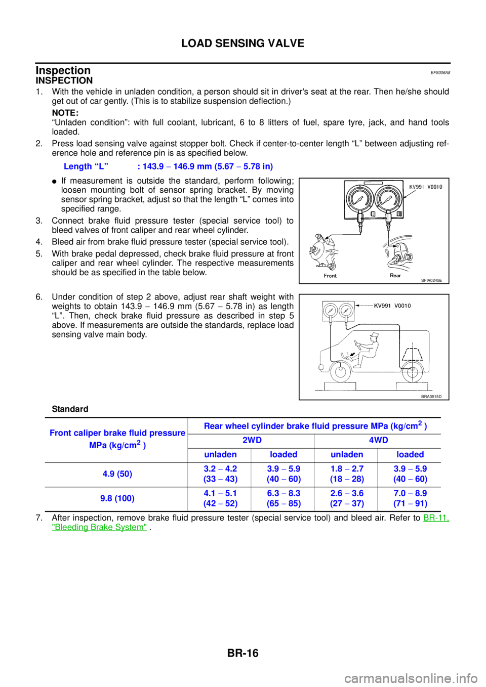
2. Press load sensing valve against stopper bolt. Check if center-to-center length “L” between adjusting ref-
erence hole and reference pin is as specified below.
lIf measurement is outside the standard, perform following;
loosen mounting bolt of sensor spring bracket. By moving
sensor spring bracket, adjust so that the length “L” comes into
specified range.
3. Connect brake fluid pressure tester (special service tool) to
bleed valves of front caliper and rear wheel cylinder.
4. Bleed air from brake fluid pressure tester (special service tool).
5. With brake pedal depressed, check brake fluid pressure at front
caliper and rear wheel cylinder. The respective measurements
should be as specified in the table below.
6. Under condition of step 2 above, adjust rear shaft weight with
weights to obtain 143.9-146.9 mm (5.67-5.78 in) as length
“L”. Then, check brake fluid pressure as described in step 5
above. If measurements are outside the standards, replace load
sensing valve main body.
Standard
7. After inspection, remove brake fluid pressure tester (special service tool) and bleed air. Refer toBR-11,
"Bleeding Brake System". Length “L” : 143.9-146.9 mm (5.67-5.78 in)
SFIA0245E
BRA0515D
Front caliper brake fluid pressure
MPa (kg/cm
2)Rear wheel cylinder brake fluid pressure MPa (kg/cm
2)
2WD 4WD
unladen loaded unladen loaded
4.9 (50)3.2-4.2
(33-43)3.9-5.9
(40-60)1.8-2.7
(18-28)3.9-5.9
(40-60)
9.8 (100)4.1-5.1
(42-52)6.3-8.3
(65-85)2.6-3.6
(27-37)7.0-8.9
(71-91)
Page 805 of 3171
BRAKE BOOSTER
BR-19
C
D
E
G
H
I
J
K
L
MA
B
BR
BRAKE BOOSTERPFP:47200
On-Vehicle ServiceEFS005ST
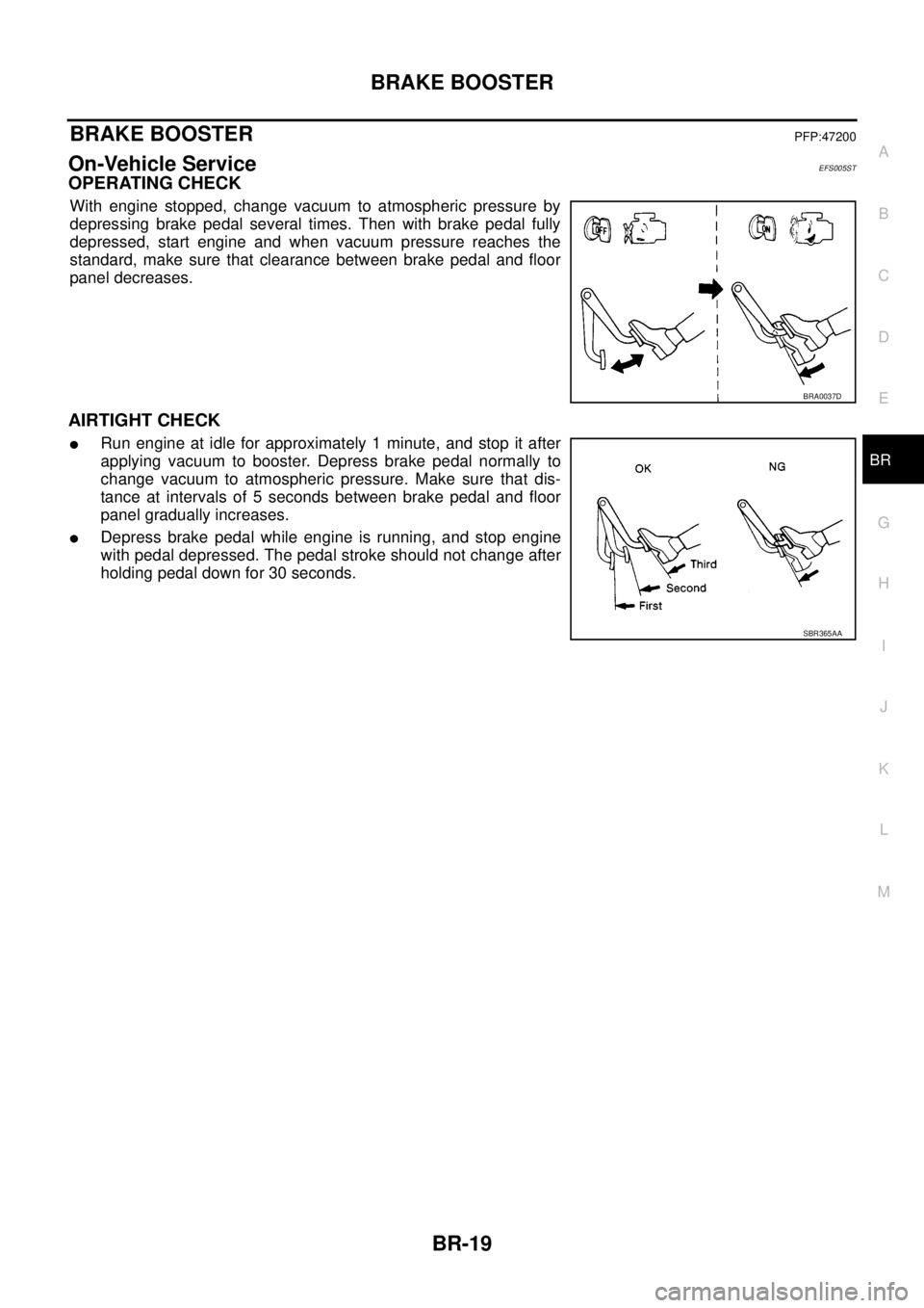
OPERATING CHECK
With engine stopped, change vacuum to atmospheric pressure by
depressing brake pedal several times. Then with brake pedal fully
depressed, start engine and when vacuum pressure reaches the
standard, make sure that clearance between brake pedal and floor
panel decreases.
AIRTIGHT CHECK
lRun engine at idle for approximately 1 minute, and stop it after
applying vacuum to booster. Depress brake pedal normally to
change vacuum to atmospheric pressure. Make sure that dis-
tance at intervals of 5 seconds between brake pedal and floor
panel gradually increases.
lDepress brake pedal while engine is running, and stop engine
with pedal depressed. The pedal stroke should not change after
holding pedal down for 30 seconds.
BRA0037D
SBR365AA
Page 821 of 3171

SERVICE DATA AND SPECIFICATIONS (SDS)
BR-35
C
D
E
G
H
I
J
K
L
MA
B
BR
SERVICE DATA AND SPECIFICATIONS (SDS)PFP:00030
General SpecificationsEFS005T8
Unit: mm (in)
Brake PedalEFS005T9
Unit: mm (in)
Brake BoosterEFS005TA
Va c u u m t y p e
Unit: mm (in)
Check ValveEFS005TB
Front Disc BrakeEFS005TC
Unit: mm (in) Front brake Brake model CLZ33VB
Cylinder bore diameter 46.4 (1.83)´2
Pad length´width´thickness 140´47.8´11 ( 5 . 5 1´1.88´0.43)
Rotor outer diameter´thickness 296´28 (11.65´1.10)
Rear brake Brake model LT30
Cylinder bore diameter 38.1 (1.50)
Lining Length´width´thickness 295´55´5.5 (11.61´2.17´0.22)
Drum inner diameter 295 (11.61)
Master cylinder Cylinder bore diameter 25.4 (1.0)
Control valve Valve model Electric brake force distribution
Brake booster Booster model C215T
Diaphragm diameterPrimary 228.5 (9.0)
Secondary 203 (8.0)
Recommended brake fluid DOT 3 or DOT 4
Brake pedal height (From dash lower panel top surface)LHD modelA/T 164.1-174.1 (6.46-6.85)
M/T 171.2-181.2 (6.74-7.13)
RHD modelA/T 174.7-184.7 (6.88-7.27)
M/T 182.1-192.1 (7.17-7.56)
Brake pedal depressed height [Under a force of 490 N (50 kg, 110 lb)
with the engine running]LHD model 120 (4.72) or more
RHD model 110 (4.33) or more
Clearance between bracket and the threaded end of the stop lamp switch 0.74 - 1.96 (0.0291 - 0.0772)
Pedal play3-11(0.12-0.43)
Input rod installation standard dimension 145 - 152 (5.71 - 5.98)
Vacuum leakage
[at vacuum of –66.7 kPa (–500 mmHg, –19.69 inHg)]within 1.3 kPa (10 mmHg, 0.39 inHg) of vacuum for 15 seconds
Brake modelCLZ33VB
Brake padStandard thickness 11.0 (0.43)
Repair limit thickness 2.0 (0.08)
Disc rotorStandard thickness 28.0 (1.102)
Repair limit 26.0 (1.024)
Thickness variation (measured at 8 positions) 0.005 (0.0002)
Runout limit (with it attached to the vehicle) 0.05 (0.002)