Page 2650 of 4323

(c) Moun")
A02859
A02889
Service Bolt
SST
Sub Gear
Main Gear
Turn
A23353Front
A23343
5 mm Hexagon
Wrench SST
A03173
± ENGINE MECHANICALCYLINDER HEAD
EM±63
2642 Author�: Date�:
2005 SEQUOIA (RM1146U)
(c) Mount the hexagon wrench head portion of the camshaft
in a vise.
NOTICE:
Be careful not to damage the camshaft.
(d) Using SST, align the holes of the camshaft main gear and
sub±gear by turning the camshaft sub±gear counter-
clockwise, and temporarily install a service bolt.
SST 09960±10010 (09962±01000, 09963±00500)
(e) Align the gear teeth of the main gear and sub±gear, and
tighten the service bolt.
7. INSTALL CAMSHAFT TIMING TUBE TO INTAKE CAM-
SHAFT
(a) Place a new oil seal to the timing tube.
NOTICE:
Be careful of the installation direction.
(b) Align the timing tube knock pin with the knock pin groove
of the drive gear, and temporarily install the drive gear
with the 4 bolts.
(c) Using SST and a 5 mm hexagon wrench, uniformly tight-
en the 4 bolts in several steps.
SST 09960±10010 (09962±01000, 09963±00500)
Torque: 7.5 N´m (76 kgf´cm, 66 in.´lbf)
NOTICE:
Be careful not to damage the timing tube.
(d) Mount the hexagon head portion of the camshaft in a vise.
NOTICE:
Be careful not to damage the camshaft.
Page 2653 of 4323

A23357
Push
A23337
A
B
C
D
E A
BC
D E
E
EE
EEE
EEEE
EE
A23337
1
4
22
8
9 2
321
6 10
17
18
5
71314
19121115
1620
A23335
Service Bolt EM±66
± ENGINE MECHANICALCYLINDER HEAD
2645 Author�: Date�:
2005 SEQUOIA (RM1146U)
(9) Push in the camshaft oil seal.
(10) Install 4 new seal washers to the bearing cap bolts
(A and B).
(11) Apply a light coat of engine oil to the threads and un-
der the heads of the bearing cap bolts (D and E).
NOTICE:
Do not apply engine oil under the heads of the bearing cap
bolts (A), (B) and (C).
HINT:
Each bolt length is indicated in the illustration.
Bolt length:
94 mm (3.70 in.) for A with seal washer
72 mm (2.83 in.) for B with seal washer
25 mm (0.98 in.) for C
52 mm (2.05 in.) for D
38 mm (1.50 in.) for E
(12) Install the oil feed pipe and the 22 bearing cap bolts
as shown in the illustration.
(13) Uniformly tighten the 22 bearing cap bolts in several
steps, in the sequence shown.
Torque:
7.5 N´m (76 kgf´cm, 66 in.´lbf) for bolt C
16 N´m (160 kgf´cm, 12 ft´lbf) for others
(14) Remove the service bolt.
Page 2656 of 4323

A23340
A
B
C
E
EA
B C
EE
E
EE
EE D
E EEE
ED
A23340
1
4
22
82
3 21
6
57
13 141912
11
15
1620
9
1017
18
A23338
Service Bolt
EM7143
Seal Packing
± ENGINE MECHANICALCYLINDER HEAD
EM±69
2648 Author�: Date�:
2005 SEQUOIA (RM1146U)
(11) Install 4 new seal washers to the bearing cap bolts
(A and B).
(12) Apply a light coat of engine oil on the threads and
under the heads of the bearing cap bolts (D and E).
NOTICE:
Do not apply engine oil under the heads of the bearing cap
bolts (A), (B) and (C).
HINT:
Each bolt length is indicated in the illustration.
Bolt length:
94 mm (3.70 in.) for A with seal washer
72 mm (2.83 in.) for B with seal washer
25 mm (0.98 in.) for C
52 mm (2.05 in.) for D
38 mm (1.50 in.) for E
(13) Install the oil feed pipe and the 22 bearing cap bolts
as shown in the illustration.
(14) Uniformly tighten the 22 bearing cap bolts in several
steps, in the sequence shown.
Torque:
7.5 N´m (76 kgf´cm, 66 in.´lbf) for bolt C
16 N´m (160 kgf´cm, 12 ft´lbf) for others
(15) Remove the service bolt.
9. CHECK AND ADJUST VALVE CLEARANCE
(See page EM±4)
Turn the camshaft so that the cam lobe faces upward, and
check and adjust the valve clearance.
10. INSTALL CAMSHAFT TIMING OIL CONTROL VALVE
(See page SF±48)
11. INSTALL SEMI±CIRCULAR PLUGS
(a) Remove any old packing material (FIPG).
(b) Apply seal packing to the semi±circular plug grooves.
Seal packing:
Part No. 08826±00080 or equivalent
Page 2718 of 4323
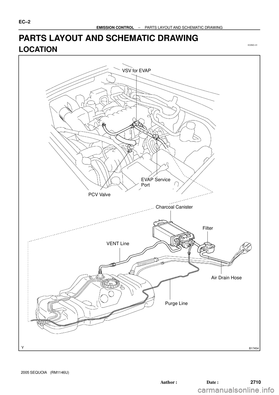
EC0NO±01
B17454
VSV for EVAP
Charcoal Canister
PCV Valve
EVAP Service
Port
Air Drain Hose VENT LineFilter
Purge Line
EC±2
± EMISSION CONTROLPARTS LAYOUT AND SCHEMATIC DRAWING
2710 Author�: Date�:
2005 SEQUOIA (RM1146U)
PARTS LAYOUT AND SCHEMATIC DRAWING
LOCATION
Page 2720 of 4323
EC089±06
B17455
Charcoal
Canister
VSV for EVAP
Air Injection
Control DriverTWC EVAP
Service
PortPurge Line VENT Line
ECM Fuel Tank
Air Filter
ECM To Intake Manifold
Pump Module
M
P
Pressure
Sensor Pump MotorVent ValveRefueling Valve
Air Inlet Line
MP
Air Switching
Valve
Air Switching
Valve No.2
VSVs Air PumpPressure
Sensor
EVAPORATIVE EMISSION (EVAP) CONTROL SYSTEM
SECONDARY AIR INJECTION SYSTEM EC±4
± EMISSION CONTROLPARTS LAYOUT AND SCHEMATIC DRAWING
2712 Author�: Date�:
2005 SEQUOIA (RM1146U)
DRAWING
Page 2725 of 4323
 CONTROL SYSTEM
EC±9
2717 Author�: Date�:
2005 SEQUOIA (RM1146U)
INSP")
EC0JL±03
B17594
Gasket
B06544
Vacuum Gauge
D13872
Hand±Held Tester
DLC3
CAN VIM
± EMISSION CONTROLEVAPORATIVE EMISSION (EVAP) CONTROL SYSTEM
EC±9
2717 Author�: Date�:
2005 SEQUOIA (RM1146U)
INSPECTION
1. INSPECT LINES AND CONNECTIONS
Visually check for loose connections, sharp bends or damage.
2. INSPECT FUEL TANK
Visually check for deformation, cracks or fuel leakage.
3. INSPECT FUEL TANK CAP
Visually check if the cap and/or gasket are deformed or dam-
aged.
If necessary, repair or replace the cap.
4. INSPECT EVAP SYSTEM LINE
(a) Warm up the engine to normal operating temperature and
stop the engine.
(b) Install a vacuum gauge (EVAP control system test equip-
ment vacuum gauge) into the EVAP service port on the
purge line.
(c) When using a hand±held tester:
Operation of the VSV for EVAP.
(1) Connect a hand±held tester to the Controller Area
Network Vehicle Interface Module (CAN VIM). Then
connect the CAN VIM to the Date Link Connector 3
(DLC3).
(2) Start the engine.
(3) Turn the hand±held tester ON.
(4) Enter the following menus: DIAGNOSIS / EN-
HANCED OBDII/ ACTIVE TEST / EVAP VAV
(ALONE)
Page 2726 of 4323
 CONTROL SYSTEM
2718 Author�: Date�:
2005 SEQUOIA (RM1146U)
(d) When not using a hand±held tester:
Ope")
B16489
Battery
B06545
Vacuum Gauge
B17595
EC±10
± EMISSION CONTROLEVAPORATIVE EMISSION (EVAP) CONTROL SYSTEM
2718 Author�: Date�:
2005 SEQUOIA (RM1146U)
(d) When not using a hand±held tester:
Operation of the VSV for the EVAP.
(1) Disconnect the VSV for the EVAP connector.
(2) Connect leads from the positive (+) and negative (±)
battery terminals to the VSV for EVAP terminals.
(3) Start the engine.
(e) Check the vacuum when the engine idles.
Vacuum:
Maintain between 0.368 and 19.713 in.Hg (5 to 268
in.Aq) for over 5 seconds
HINT:
If the vacuum does not change, the hose connecting the VSV
and the service port is loose or blocked, or the VSV is malfunc-
tioning.
(f) When using a hand±held tester:
Conclude operation of the VSV for EVAP.
(1) Stop the engine.
(2) Disconnect the hand±held tester from the DLC3.
(g) When not using a hand±held tester:
Conclude operation of the VSV for EVAP.
(1) Stop the engine.
(2) Disconnect the positive (+) and negative (±) leads
of the battery from the VSV for EVAP terminals.
(3) Connect the VSV for EVAP connector.
(h) Disconnect the vacuum gauge from the EVAP service
port on the purge line.
(i) Connect a pressure gauge to the EVAP service port on
the purge line.
(j) Check the pressure.
(1) Prepare a rubber hose that has an inside diameter
of 15 to 18.5 mm.
(2) Disconnect the atmospheric side hose of the pump
module.
(3) Connect the prepared rubber hose to the pump
module, and pinch the rubber hose with the clip to
prevent air from entering into the canister passage.
Page 2727 of 4323
 CONTROL SYSTEM
EC±11
2719 Author�: Date�")
B06546
Pressure Gauge
Pressure
B17596
Fuel Tank Cap
Pressure
Gauge
B17662
Fuel Tank CapFuel Tank
Vent Line Hose
± EMISSION CONTROLEVAPORATIVE EMISSION (EVAP) CONTROL SYSTEM
EC±11
2719 Author�: Date�:
2005 SEQUOIA (RM1146U)
(4) Apply pressure (13.5 to 15.5 in.Aq, 0.99 to 1.14
in.Hq) from the EVAP service port.
Pressure:
The gauge should still read over 7.7 to 8.8 in.Aq (0.57
to 0.65 in.Hq) for 2 minutes after the pressure is ap-
plied.
HINT:
If you cannot apply pressure, the hose connecting the VSV,
charcoal canister and fuel tank has slipped off or the VSV is
open.
(5) Check if the pressure decreases when the fuel tank
cap is removed while applying pressure.
HINT:
If the pressure does not decrease when the filler cap is re-
moved, the hose connecting the service port and the fuel tank
may be blocked.
(k) Disconnect the pressure gauge from the EVAP service
port on the purge line.
5. INSPECT FUEL CUTOFF VALVE AND FILL CHECK
VA LV E
(a) Disconnect the vent line hose from the fuel tank.
(b) Connect the pressure gauge to the fuel tank.
(c) Fill the fuel tank with fuel.
(d) Apply pressure of 4 kPa (41 gf/cm
2,0.58 psi) to the vent
port of the fuel tank.
HINT:
It is necessary to check the amount of fuel in the fuel tank. When
the fuel tank is full, the float valve of the fill check valve is closed
and no air can pass through.
(e) Remove the fuel tank cap, and check that the pressure
drops.
If the pressure does not drop, replace the fuel tank assembly.
(f) Reconnect the vent line hose to the fuel tank.