Page 3591 of 4323
H16683
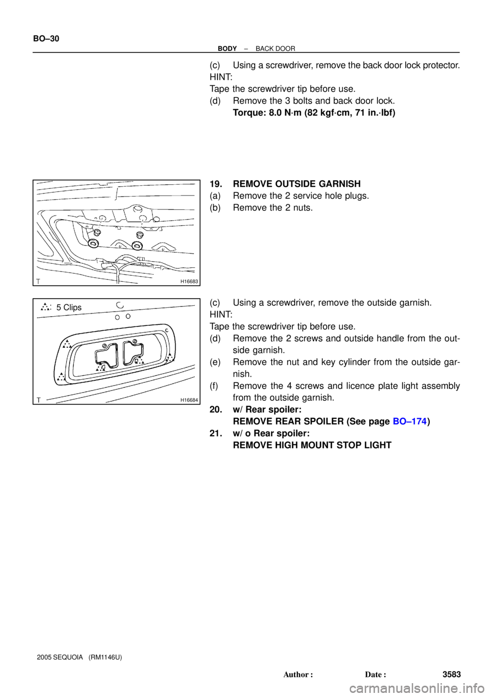
H16684
5 Clips BO±30
± BODYBACK DOOR
3583 Author�: Date�:
2005 SEQUOIA (RM1146U)
(c) Using a screwdriver, remove the back door lock protector.
HINT:
Tape the screwdriver tip before use.
(d) Remove the 3 bolts and back door lock.
Torque: 8.0 N´m (82 kgf´cm, 71 in.´lbf)
19. REMOVE OUTSIDE GARNISH
(a) Remove the 2 service hole plugs.
(b) Remove the 2 nuts.
(c) Using a screwdriver, remove the outside garnish.
HINT:
Tape the screwdriver tip before use.
(d) Remove the 2 screws and outside handle from the out-
side garnish.
(e) Remove the nut and key cylinder from the outside gar-
nish.
(f) Remove the 4 screws and licence plate light assembly
from the outside garnish.
20. w/ Rear spoiler:
REMOVE REAR SPOILER (See page BO±174)
21. w/ o Rear spoiler:
REMOVE HIGH MOUNT STOP LIGHT
Page 3596 of 4323
BO45Z±01
H09481
H16691
± BODYFRONT WIPER AND WASHER
BO±35
3588 Author�: Date�:
2005 SEQUOIA (RM1146U)
REMOVAL
1. REMOVE WIPER ARMS
(a) Using a screwdriver, remove the 2 caps.
HINT:
Tape the screwdriver tip before use.
(b) Remove the 2 nuts and wiper arms.
2. REMOVE COWL TOP VENTILATOR LOUVER
(a) Using a clip remover, remove the 6 clips.
(b) Remove the 8 screws and cowl top ventilator louver.
3. REMOVE HOOD TO COWL TOP SEAL
Remove the hood to cowl top seal from the cowl top ventilator
louver.
4. REMOVE WIPER MOTOR
(a) Disconnect the connector.
(b) Unfasten the 4 bolts.
(c) Disconnect the wiper motor from the wiper link, then re-
move the wiper motor.
5. REMOVE WIPER LINK
(a) Remove the 6 bolts.
(b) Remove the wiper link through the service hole.
6. REMOVE WASHER NOZZLE
(a) Disconnect the washer hose.
(b) Using a screwdriver, remove the nozzle.
HINT:
Tape the screwdriver tip before use.
(c) Employ the same manner described above to the other
side.
Page 3599 of 4323

INSTALLATION
1. INSTALL WASHER NOZZLES
2. INSTALL WIPER LINK
Ins")
BO462±01
H02485
Wiper Link
Cowl Panel
H09483
AB
C
C BO±38
± BODYFRONT WIPER AND WASHER
3591 Author�: Date�:
2005 SEQUOIA (RM1146U)
INSTALLATION
1. INSTALL WASHER NOZZLES
2. INSTALL WIPER LINK
Install the wiper link through the service hole, then torque the
6 bolts.
Torque: 5.5 N´m (56 kgf´cm, 49 in.´lbf)
3. INSTALL WIPER MOTOR
(a) Install the wiper motor to the wiper link.
HINT:
When installing the wiper motor, connect the claw of wiper link
to the cowl panel shown in the illustration.
(b) Torque the 4 bolts.
Torque: 5.5 N´m (56 kgf´cm, 49 in.´lbf)
(c) Connect the connector.
4. INSTALL HOOD TO COWL TOP SEAL
Install the hood to cowl top seal to the cowl top ventilator louver.
5. INSTALL COWL TOP VENTILATOR LOUVER
Install the cowl top ventilator louver with the 8 screws and 6
clips.
6. INSTALL WIPER ARMS
(a) Operate the wiper once and turn the wiper switch OFF.
(b) Install the wiper arms and tighten the nuts by hand.
(c) Adjust the installation positions of the wiper arms to the
positions shown in the illustration.
A: Approx. 25.4 mm (1.000 in)
B: Approx. 40.0 mm (1.574 in)
HINT:
When installing the wiper arms, make sure that the tips of the
blades are not beyond the ceramic edge as indicated ºCº part
in the illustration.
(d) Torque the 2 nuts.
Torque: 20 N´m (205 kgf´cm, 15 ft´lbf)
(e) Install the 2 caps.
Page 3600 of 4323
BO463±01
H16777
Washer Nozzle
Back Door Glass
Rear Wiper Arm Back Door Center Garnish
Back Door
Side Garnish
Power Window
Regulator
Step Liner
Service Hole CoverWiper Motor
Grommet
Rear Wiper Motor
Back Door Side Garnish
No. 2 Service
Hole Cover
Strap Cover
No. 1 Service Hole Cover
Back Door Trim Board
Back Door Pull Strap
: Specified torque
N´m (kgf´cm, ft´lbf)
5.5 (56, 49 in.´lbf)
8.0 (82, 71 in.´lbf)
5.5 (56, 49 in.´lbf)
8.0 (82, 71 in.´lbf)
± BODYREAR WIPER AND WASHER
BO±39
3592 Author�: Date�:
2005 SEQUOIA (RM1146U)
REAR WIPER AND WASHER
COMPONENTS
Page 3602 of 4323
H16677
H16678
H16680
H16682
± BODYREAR WIPER AND WASHER
BO±41
3594 Author�: Date�:
2005 SEQUOIA (RM1146U)
7. REMOVE NO. 1 SERVICE HOLE COVER
8. REMOVE NO. 2 SERVICE HOLE COVER
9. REMOVE BACK DOOR GLASS
(a) Open the back door glass until the bolts appear in the ser-
vice hole.
(b) Disconnect the connector.
(c) Remove the 2 bolts and guide bracket.
(d) Remove the 4 bolts and back door glass as shown in the
illustration.
NOTICE:
Be careful not to drop the back door glass.
10. REMOVE POWER WINDOW REGULATOR
(a) Disconnect the connector.
(b) Disengage the connector and clamp.
(c) Remove the 4 nuts and power window regulator.
HINT:
Remove the power window regulator through the service hole.
11. REMOVE REAR WIPER MOTOR
(a) Disconnect the connector.
(b) Disengage the connector and clamp.
(c) Remove the service hole plug.
(d) Unfasten the 3 bolts, then remove the rear wiper motor.
Page 3606 of 4323

H16698
± BODYREAR WIPER AND WASHER
BO±45
3598 Author�: Date�:
2005 SEQUOIA (RM1146U)
INSTALLATION
1. INSTALL WASHER NOZZLE
2. INSTALL R")
BO467±02
H16696
Mark
Mark to Upward
H16697
10 mm
(0.39 in.)
H16698
± BODYREAR WIPER AND WASHER
BO±45
3598 Author�: Date�:
2005 SEQUOIA (RM1146U)
INSTALLATION
1. INSTALL WASHER NOZZLE
2. INSTALL REAR WIPER MOTOR
(a) Install the rear wiper motor, then torque the 3 bolts.
Torque: 5.5 N´m (56 kgf´cm, 49 in.´lbf)
(b) Engage the connector and clamp.
(c) Connect the connector.
3. INSTALL POWER WINDOW REGULATOR
Torque: 5.5 N´m (56 kgf´cm, 49 in.´lbf)
4. INSTALL BACK DOOR GLASS
Torque: 8.0 N´m (82 kgf´cm, 71 in.´lbf)
5. INSTALL NO. 2 SERVICE HOLE COVER
6. INSTALL NO. 1 SERVICE HOLE COVER
7. INSTALL BACK DOOR TRIM BOARD
8. INSTALL BACK DOOR SIDE GARNISH
9. INSTALL BACK DOOR CENTER GARNISH
10. INSTALL BACK DOOR PULL STRAP
11. INSTALL STEP LINER
12. INSTALL REAR WIPER ARM
(a) Install the rear wiper motor grommet as shown in the il-
lustration.
(b) Operate the wiper once and turn the wiper switch OFF.
(c) Install the wiper arm as shown in the illustration, then
torque the nut.
Torque: 5.5 N´m (56 kgf´cm, 49 in.´lbf)
(d) Set the wiper arm to rise±up position as shown in the il-
lustration.
(e) Close the cover.
13. PERFORM INITIALIZATION (See page IN±20)
Back door power window control system needs initialization
when disconnecting the cable from the negative battery termi-
nal.
Page 3659 of 4323
BO4HM±01
H18897
Assist Gripw/ Rear A/C:
Rear No. 6 Air Duct
Roof Console BoxLens Map Lightw/ Rear No. 2 seat:
Assist Grip
Dome Light
LensRear Trim Roof Headlining
w/ Rear No. 2 seat:
Rear Trim Cover w/ Double Sun Visor:
Roof Headlining Roof Console Box
w/o Rear No. 2 seat:
Service Hole Cover
w/ Rear No. 2 seat:
Assist Grip
w/o Rear No. 2 seat:
Service Hole Cover
Sun VisorRoof Headlining
w/ Electro chrmic
inner rear view mirror:
Mirror Coverw/ Sliding roof:
Sun Visor
Sun Visor
Holder Holder
Assist Grip
Map Light
Lens
Sliding Roof Opening Trim
w/ Rear A/C:
Rear No.5 Air Duct
BO±98
± BODYROOF HEADLINING
3651 Author�: Date�:
2005 SEQUOIA (RM1146U)
ROOF HEADLINING
COMPONENTS
Page 3727 of 4323

DISPOSAL
HINT:
When scrapping vehicle equipped with a SRS or disposing of
a front seat outer be")
BO47S±02
AB0152
SST BO±166
± BODYSEAT BELT PRETENSIONER
3719 Author�: Date�:
2005 SEQUOIA (RM1146U)
DISPOSAL
HINT:
When scrapping vehicle equipped with a SRS or disposing of
a front seat outer belt (with seat belt pretensioner), always first
deploy the airbag in accordance with the procedure given in RS
section or activate the seat belt pretensioner. If any abnormality
occurs with the airbag deployment or seat belt pretensioner ac-
tivation, contact the SERVICE DEP. of the TOYOTA MOTOR
SALES, U.S.A. INC. When disposing of a front seat outer belt
(with seat belt pretensioner) activated in a collision, follow the
same procedure given in step 1±(d) in ºDISPOSALº.
CAUTION:
�Never dispose of front seat outer belt which has inac-
tivated pretensioner.
�The seat belt pretensioner produces a sizeable ex-
ploding sound when it activates, so perform the op-
eration out±of±door and where it will not create a nui-
sance to nearby residents.
�When activating the seat belt pretensioner, always
use the specified SST. (SRS Airbag Deployment Tool)
Perform the operation in a place away from electrical
noise.
SST 09082±00700, 09082±00740
�When activating a front seat outer belt (with seat belt
pretensioner), perform the operation at least
10 m (33 ft) away from the front seat outer belt.
�Use gloves and safety glasses when handling a front
seat outer belt with activated pretensioner.
�Always wash your hands with water after completing
the operation.
�Do not apply water, etc. to a front seat outer belt with
activated pretensioner.