Page 2302 of 4323

I28277
*1
*2
*4*3*6
*5 *7
*8 *8
*8
DI±2100
± DIAGNOSTICSREAR SEAT ENTERTAINMANT SYSTEM
2294 Author�: Date�:
2005 SEQUOIA (RM1146U)
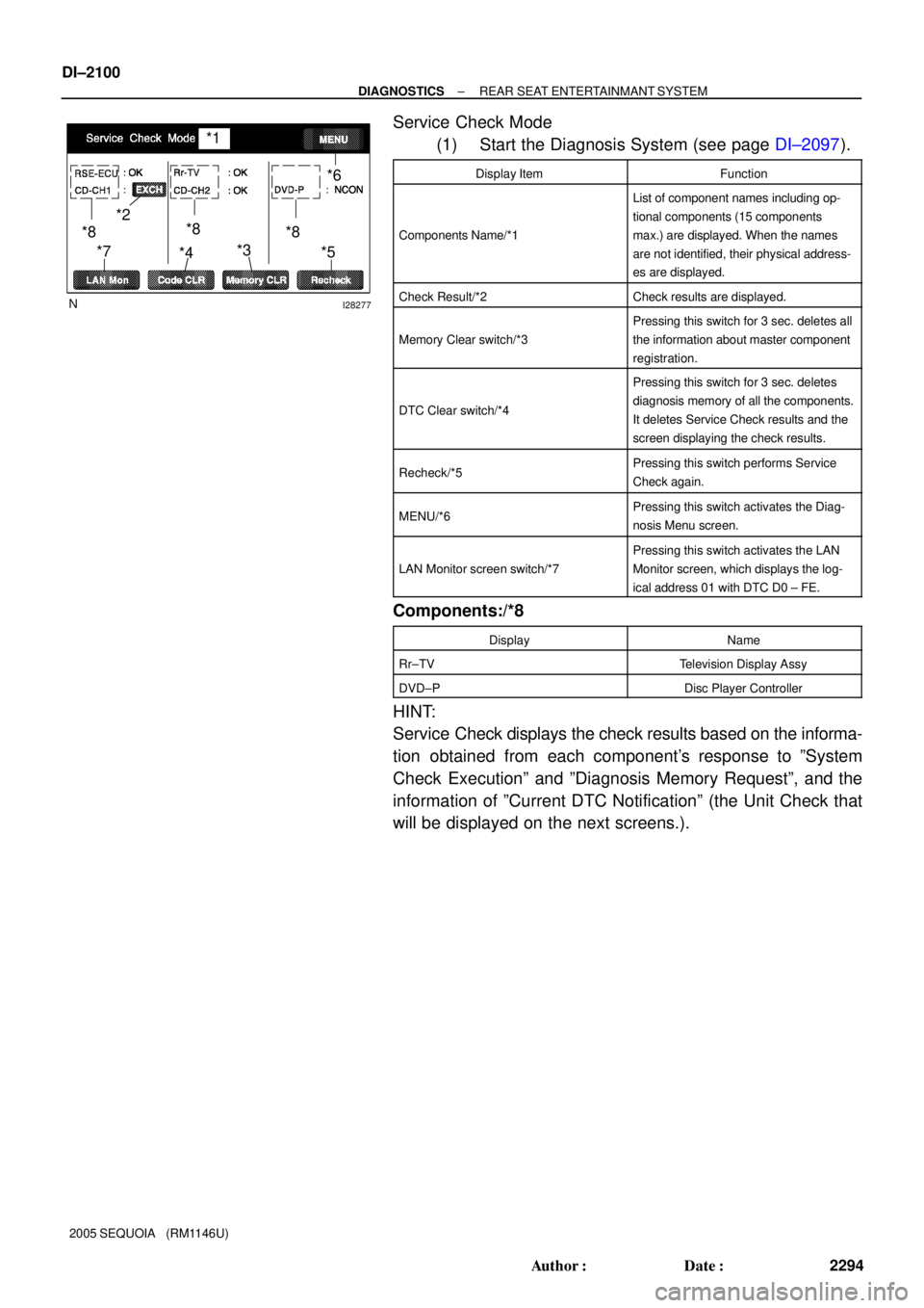
Service Check Mode
(1) Start the Diagnosis System (see page DI±2097).
Display ItemFunction
Components Name/*1
List of component names including op-
tional components (15 components
max.) are displayed. When the names
are not identified, their physical address-
es are displayed.
Check Result/*2Check results are displayed.
Memory Clear switch/*3
Pressing this switch for 3 sec. deletes all
the information about master component
registration.
DTC Clear switch/*4
Pressing this switch for 3 sec. deletes
diagnosis memory of all the components.
It deletes Service Check results and the
screen displaying the check results.
Recheck/*5Pressing this switch performs Service
Check again.
MENU/*6Pressing this switch activates the Diag-
nosis Menu screen.
LAN Monitor screen switch/*7
Pressing this switch activates the LAN
Monitor screen, which displays the log-
ical address 01 with DTC D0 ± FE.
Components:/*8
DisplayName
Rr±TVTelevision Display Assy
DVD±PDisc Player Controller
HINT:
Service Check displays the check results based on the informa-
tion obtained from each component's response to ºSystem
Check Executionº and ºDiagnosis Memory Requestº, and the
information of ºCurrent DTC Notificationº (the Unit Check that
will be displayed on the next screens.).
Page 2303 of 4323

I28278
*1
*4*3
*2
*5*6
± DIAGNOSTICSREAR SEAT ENTERTAINMANT SYSTEM
DI±2101
2295 Author�: Date�:
2005 SEQUOIA (RM1146U)
(2) Read Check Result
Check ResultMeaning
OKNo DTC is identified.
EXCHOne or more DTC requesting for exchange are detected.
CHEKOne or more DTC requesting for check are detected.
NCON
No connection response to Diagnosis System start±up,
whereas it has the connection response to the AVC±LAN
system when the power switch is turned on (when IG is
turned to ACC).
OldOne or more DTC are detected because of old version.
NRESNo response to the information about the Diagnosis System,
whereas it responds to the Diagnosis System start±up.
HINT:
�After repair and check, press ºCode CLRº for more than
3 sec. to delete diagnosis memory.
�After deleting diagnosis memory, press ºRecheckº and
make sure ºOKº is displayed on the screen.
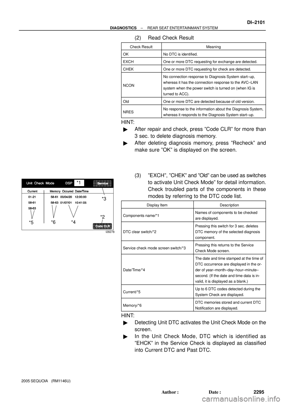
(3) ºEXCHº, ºCHEKº and ºOldº can be used as switches
to activate Unit Check Modeº for detail information.
Check troubled parts of the components in these
modes by referring to the DTC code list.
Display ItemDescription
Components name/*1Names of components to be checked
are displayed.
DTC clear switch/*2
Pressing this switch for 3 sec. deletes
DTC memory of the selected diagnosis
component.
Service check mode screen switch/*3Pressing this returns to the Service
Check Mode screen.
Date/Time/*4
The date and time stamped at the time of
DTC occurrence are displayed in the or-
der of year±month±day±hour±minute±
second. (If the date and time data is in-
valid, it is displayed as a blank.)
Current/*5Up to 6 DTC codes detected during the
System Check are displayed.
Memory/*6DTC memories stored and current DTC
Notification are displayed.
HINT:
�Detecting Unit DTC activates the Unit Check Mode on the
screen.
�In the Unit Check Mode, DTC which is identified as
ºEHCKº in the Service Check is displayed as classified
into Current DTC and Past DTC.
Page 2342 of 4323
DI±2140
± DIAGNOSTICSREAR SEAT ENTERTAINMANT SYSTEM
2334 Author�: Date�:
2005 SEQUOIA (RM1146U)
INSPECTION PROCEDURE
1 Inspect apparatus.
CHECK:
Choose the apparatus to be inspected.
RESULT:
Television display assyGo to step A
Radio and navigation assy (w/ Navigation System)Go to step B
Radio receiver assy (w/o Navigation System)Go to step C
Disc player controllerGo to step D
B Go to step 4.
C Go to step 6.
D Go to step 7.
A
2 Service check mode (Television display assy).
CHECK:
Perform the service check (See page DI±2099).
Start the diagnosis system and read the check result for the television display assy.
RESULT:
ºNCONº is displayed or result is not displayed (Rr±TV)Go to step A
ºGOODº is displayedGo to step B
HINT:
�This system has 2 kinds of AVC±LAN: main AVC±LAN and sub AVC±LAN. The television display is
connected for the sub AVC±LAN.
�Perform the communication check for the diagnosis system (See page DI±2097).
B Replace multi±display controller sub±assy.
A
Page 2344 of 4323
DI±2142
± DIAGNOSTICSREAR SEAT ENTERTAINMANT SYSTEM
2336 Author�: Date�:
2005 SEQUOIA (RM1146U)
4 Service check mode (Multi±display controller sub±assy).
CHECK:
Perform the service check (See page DI±2099).
Start the diagnosis system and read the check result for the radio and navigation assy.
RESULT:
ºNCONº is displayed or result is not displayed (RSE ECU)Go to step A
ºGOODº is displayedGo to step B
HINT:
�This system has 2 kinds of AVC±LAN: main AVC±LAN and sub AVC±LAN. The television display is
connected for the sub AVC±LAN.
�Perform the communication check for the diagnosis system (See page DI±2097).
B Replace radio and navigation assy.
A
Page 2345 of 4323

I28750
Radio and Navigation Assy:
TX±TX+
R27
I28614
TX+ Multi±display Controller Sub±assy:
R23TX±
± DIAGNOSTICSREAR SEAT ENTERTAINMANT SYSTEM
DI±2143
2337 Author�: Date�:
2005 SEQUOIA (RM1146U)
5 Check harness and connector (Radio and navigation assy ± multi±display con-
troller sub±assy).
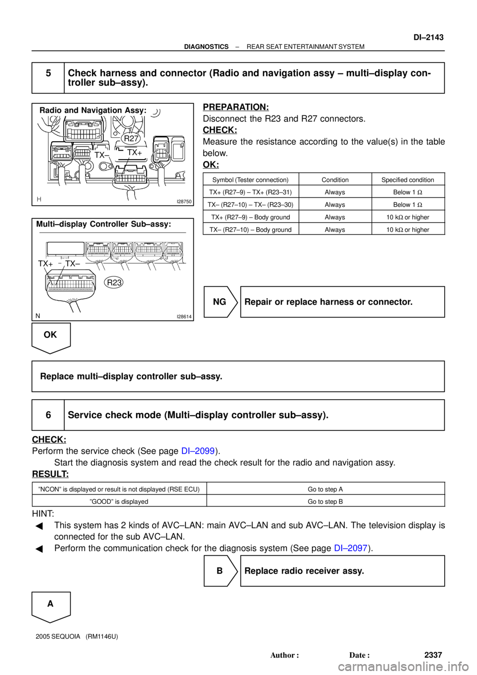
PREPARATION:
Disconnect the R23 and R27 connectors.
CHECK:
Measure the resistance according to the value(s) in the table
below.
OK:
Symbol (Tester connection)ConditionSpecified condition
TX+ (R27±9) ± TX+ (R23±31)AlwaysBelow 1 W
TX± (R27±10) ± TX± (R23±30)AlwaysBelow 1 W
TX+ (R27±9) ± Body groundAlways10 kW or higher
TX± (R27±10) ± Body groundAlways10 kW or higher
NG Repair or replace harness or connector.
OK
Replace multi±display controller sub±assy.
6 Service check mode (Multi±display controller sub±assy).
CHECK:
Perform the service check (See page DI±2099).
Start the diagnosis system and read the check result for the radio and navigation assy.
RESULT:
ºNCONº is displayed or result is not displayed (RSE ECU)Go to step A
ºGOODº is displayedGo to step B
HINT:
�This system has 2 kinds of AVC±LAN: main AVC±LAN and sub AVC±LAN. The television display is
connected for the sub AVC±LAN.
�Perform the communication check for the diagnosis system (See page DI±2097).
B Replace radio receiver assy.
A
Page 2347 of 4323

I28617
Disc Player Controller:
Multi±display Controller Sub±assy:TX±
TX+
TX3±
TX3+
D23
R22
± DIAGNOSTICSREAR SEAT ENTERTAINMANT SYSTEM
DI±2145
2339 Author�: Date�:
2005 SEQUOIA (RM1146U)
8 Service check mode (Disc player controller).
CHECK:
Perform the service check (See page DI±2099).
Start the diagnosis system and read the check result for the disc player controller.
RESULT:
ºNCONº is displayed or result is not displayed (DVD±P)Go to step A
ºGOODº is displayedGo to step B
HINT:
�This system has 2 kinds of AVC±LAN: main AVC±LAN and sub AVC±LAN. The television display is
connected for the sub AVC±LAN.
�Perform the communication check for the diagnosis system (See page DI±2097).
B Replace multi±display controller sub±assy.
A
9 Check harness and connector (Disc player controller ± Multi±display controller
sub±assy).
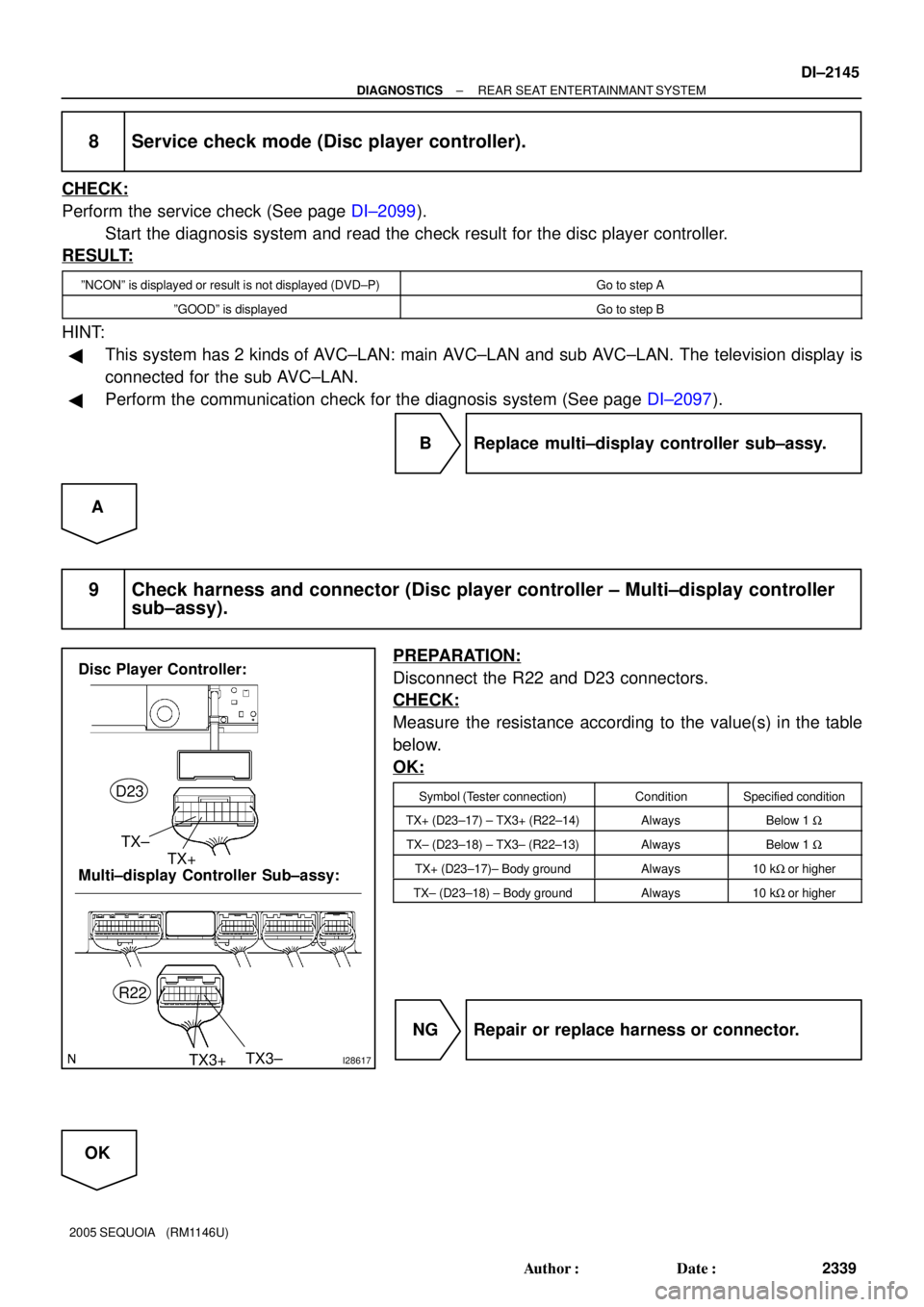
PREPARATION:
Disconnect the R22 and D23 connectors.
CHECK:
Measure the resistance according to the value(s) in the table
below.
OK:
Symbol (Tester connection)ConditionSpecified condition
TX+ (D23±17) ± TX3+ (R22±14)AlwaysBelow 1 W
TX± (D23±18) ± TX3± (R22±13)AlwaysBelow 1 W
TX+ (D23±17)± Body groundAlways10 kW or higher
TX± (D23±18) ± Body groundAlways10 kW or higher
NG Repair or replace harness or connector.
OK
Page 2376 of 4323

DIDBU±01
30 kHz 300 kHz 3 MHz 30 MHz 300 MHz
LF MF HF VHF
AM FM
Frequency modulation Frequency
Designation
Radio wave
Modulation Amplitude modulation
BE2818
FM (Stereo)
FM (Monaural)
AM
BE2819
Ionosphere Phasing: DI±2174
± DIAGNOSTICSNAVIGATION SYSTEM
2368 Author�: Date�:
2005 SEQUOIA (RM1146U)
IDENTIFICATION OF NOISE SOURCE
Radio Description
(a) Radio frequency band
Radio Broadcasts use the radio frequency bands shown in the table below.
LF: Low Frequency
MF: Medium Frequency
HF: High Frequency
VHF: Very High Frequency
(b) Service area
The service areas of the AM and FM broadcasts are vast-
ly different. Even if an AM broadcast has clear reception,
an FM broadcast originating in the same location may not
be received at all.
The service area of FM stereo broadcasts is small, and
static as well as interference (noise) easily enters the sig-
nal.
(c) Radio reception problems
HINT:
In addition to static, other problems such as ºphasingº, ºmulti±pathº, and ºfade outº exist. These problems
are not caused by electrical noise, but by the radio signal propagation method itself.
(1) Phasing
The AM frequency band reflects off the earth's iono-
sphere at night. When this occurs, the reflected sig-
nal may interfere with the direct signal sent by the
same transmitter. This phenomenon is known as
ºphasingº.
Page 2393 of 4323

DIDC5±01
I28205
I28206
Upper Left
Lower Left
I28207
± DIAGNOSTICSNAVIGATION SYSTEM
DI±2191
2385 Author�: Date�:
2005 SEQUOIA (RM1146U)
DIAGNOSIS SYSTEM
HINT:
�Illustrations may differ from the actual vehicle depending on the device settings and options. There-
fore, some detailed areas may not be shown exactly the same as on the actual vehicle.
�After the ignition switch is turned on, check that the map is displayed before starting the diagnostic
mode. Otherwise, some items cannot be checked.
1. There are 2 methods to start diagnostic mode. Start the mode by using one of them.
2. Method 1
(a) Start the engine.
(b) While pressing and holding ºINFOº switch, operate the
light control switch, OFF " TAIL " OFF " TAIL " OFF
" TAIL " OFF.
(c) The diagnostic mode starts and the service check screen
(ºSystem Check Modeº) will be displayed. Service inspec-
tion starts automatically and the result will be displayed.
3. Method 2
(a) Start the engine.
(b) Switch to the ºDisplay quality adjustmentº screen.
(c) From the display quality adjustment screen, touch the
corners of the screen in the following order: upper left "
lower left "upper left " lower left " upper left " lower
left.
(d) The diagnostic mode starts and ºService Checkº screen
will be displayed. Service inspection starts automatically
and the result will be displayed.
4. Diagnosis MENU
(a) Diagnostic screen will be displayed by pressing the menu
switch on the service check screen.