Page 2396 of 4323

I28238
*1
*2
*3 *5
*4
*6
I28239
*1
DI±2194
± DIAGNOSTICSNAVIGATION SYSTEM
2388 Author�: Date�:
2005 SEQUOIA (RM1146U)
(2) Unit Check Mode Screen
Screen Description
DisplayContents
Device name/*1Target device
Segment/*2Target device logical address
DTC/*3DTC (Diagnostic Trouble Code)
Timestamp/*4The time and date of past DTCs are displayed (The year is displayed in 2 digit
format.).
Present Code/*5The DTC output at the service check is displayed.
Past Code/*6Diagnostic memory results and recorded DTCs are displayed.
(3) LAN Monitor (Original) Screen
Check Result/*1
HINT:
Check results of all the devices are displayed.
ResultMeaningAction
No Err
(OK)There are no communication DTCs.±
CHEKThe device responds with a ºcheckº±type DTC.Look up the DTC in ºUnit Check Modeº.
NCONThe device was previously present, but does not respond in
diagnostic mode.1. Check power supply wire harness of the device.
2. Check the AVC±LAN of the device.
OldThe device responded with an old±type DTC.Look up the DTC in ºUnit Check Modeº.
NRESDevice responds in diagnostic mode, but gives no DTC
information.1. Check power supply wire harness of the device.
2. Check the AVC±LAN of the device.
Page 2401 of 4323

DIDC6±01
I28208Logical AddressDiagnostic Code
I28209
Logical AddressDiagnostic Code
± DIAGNOSTICSNAVIGATION SYSTEM
DI±2199
2393 Author�: Date�:
2005 SEQUOIA (RM1146U)
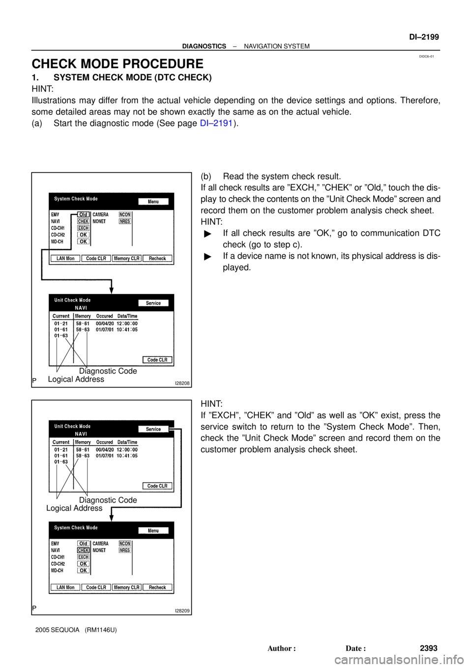
CHECK MODE PROCEDURE
1. SYSTEM CHECK MODE (DTC CHECK)
HINT:
Illustrations may differ from the actual vehicle depending on the device settings and options. Therefore,
some detailed areas may not be shown exactly the same as on the actual vehicle.
(a) Start the diagnostic mode (See page DI±2191).
(b) Read the system check result.
If all check results are ºEXCH,º ºCHEKº or ºOld,º touch the dis-
play to check the contents on the ºUnit Check Modeº screen and
record them on the customer problem analysis check sheet.
HINT:
�If all check results are ºOK,º go to communication DTC
check (go to step c).
�If a device name is not known, its physical address is dis-
played.
HINT:
If ºEXCHº, ºCHEKº and ºOldº as well as ºOKº exist, press the
service switch to return to the ºSystem Check Modeº. Then,
check the ºUnit Check Modeº screen and record them on the
customer problem analysis check sheet.
Page 2403 of 4323
I28212
I28213
I28214
± DIAGNOSTICSNAVIGATION SYSTEM
DI±2201
2395 Author�: Date�:
2005 SEQUOIA (RM1146U)
HINT:
If check results of other devices are ºCHEK,º press the ºServiceº
switch to return to the original ºLAN Monitorº screen. Then,
check the individual communication diagnostic screen for the
next device and record the result on the customer problem anal-
ysis check sheet.
2. SYSTEM CHECK MODE (DTC CLEAR/RECHECK)
HINT:
Illustrations may differ from the actual vehicle depending on the device settings and options. Therefore,
some detailed areas may not be shown exactly the same as on the actual vehicle.
(a) Enter diagnostic mode (See page DI±2191).
(b) Clear DTC
(1) Press the ºCode CLRº switch for 3 seconds.
(2) Check result is cleared.
(c) Recheck
(1) Press the ºRecheckº switch.
Page 2471 of 4323

I28747
Radio and Navigation Assy
Wire Harness View:
ATX+
ATX±
R30
I28752TX+TX±
S10
Stereo Component Amplifier Assy
Wire Harness View:
± DIAGNOSTICSNAVIGATION SYSTEM
DI±2269
2463 Author�: Date�:
2005 SEQUOIA (RM1146U)
INSPECTION PROCEDURE
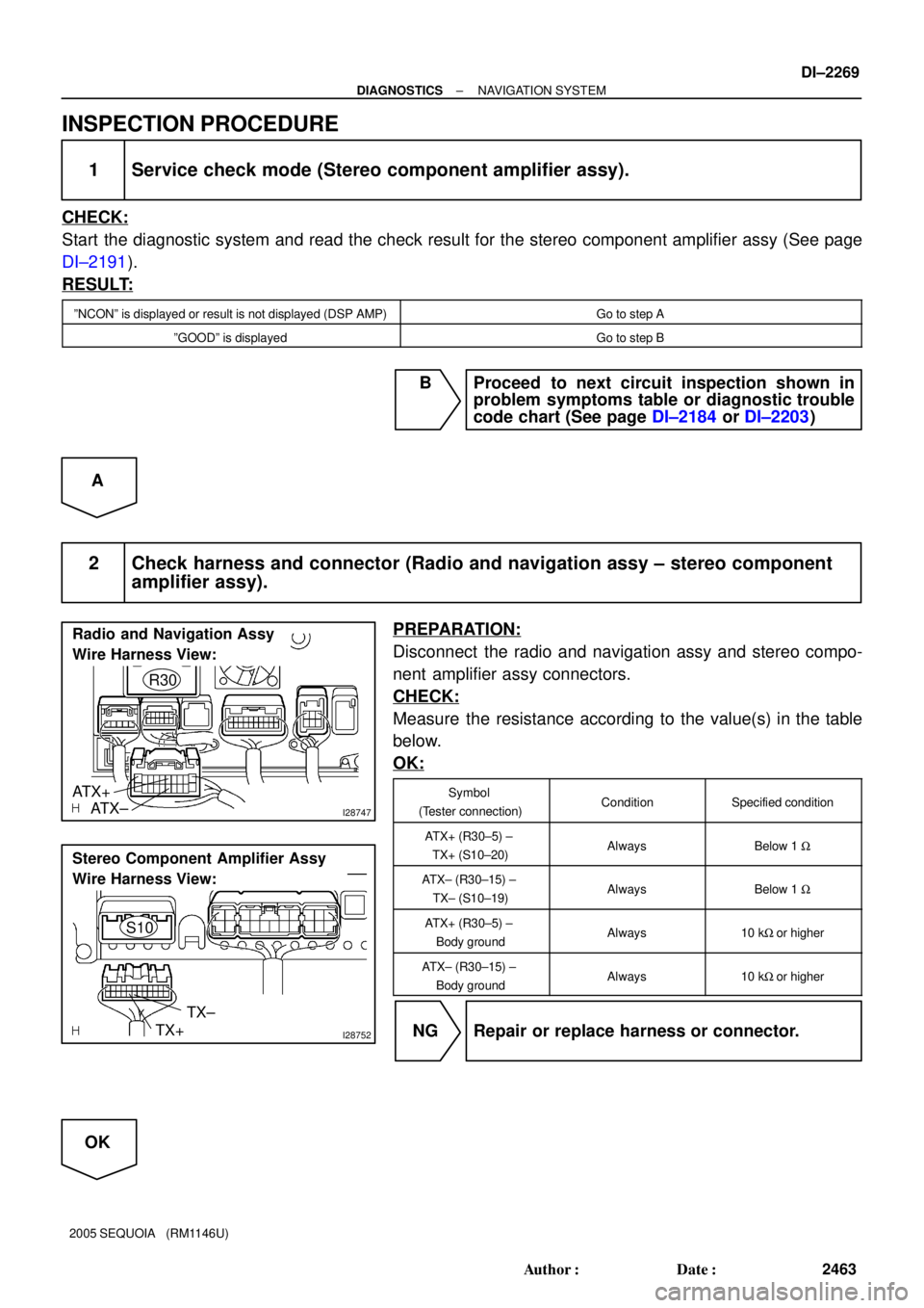
1 Service check mode (Stereo component amplifier assy).
CHECK:
Start the diagnostic system and read the check result for the stereo component amplifier assy (See page
DI±2191).
RESULT:
ºNCONº is displayed or result is not displayed (DSP AMP)Go to step A
ºGOODº is displayedGo to step B
B Proceed to next circuit inspection shown in
problem symptoms table or diagnostic trouble
code chart (See page DI±2184 or DI±2203)
A
2 Check harness and connector (Radio and navigation assy ± stereo component
amplifier assy).
PREPARATION:
Disconnect the radio and navigation assy and stereo compo-
nent amplifier assy connectors.
CHECK:
Measure the resistance according to the value(s) in the table
below.
OK:
Symbol
(Tester connection)ConditionSpecified condition
ATX+ (R30±5) ±
TX+ (S10±20)AlwaysBelow 1 W
ATX± (R30±15) ±
TX± (S10±19)AlwaysBelow 1 W
ATX+ (R30±5) ±
Body groundAlways10 kW or higher
ATX± (R30±15) ±
Body groundAlways10 kW or higher
NG Repair or replace harness or connector.
OK
Page 2500 of 4323
DI±2298
± DIAGNOSTICSAIR CONDITIONING SYSTEM
2492 Author�: Date�:
2005 SEQUOIA (RM1146U)
9. SUPPLEMENTAL RESTRAINT SYSTEM (SRS)
The SEQUOIA is equipped with an SRS (Supplemental Re-
straint System) such as the driver, passenger, side, curtain
shield airbag. Failure to carry out service operation in the cor-
rect sequence could cause the SRS to unexpectedly deploy
during servicing, possibly leading to a serious accident. Before
servicing (including removal or installation of parts, inspection
or replacement), be sure to read the precautionary notices tn
the RS section.
10. INITIALIZATION
NOTICE:
When disconnecting the battery terminal, initialize the fol-
lowing system after the terminal is reconnected.
System NameSee Page
Back Door Power Window Control Sys-
temBE±77
Page 2627 of 4323

A04456
No.2 Idler
Pulley Bolt
Timing
Mark
Crankshaft
Pulley Bolt
A23334
Movement
(25°)
SSTOil Control Valve
Installation Hole
A23335Service Bolt
A23336
EM±40
± ENGINE MECHANICALCYLINDER HEAD
2619 Author�: Date�:
2005 SEQUOIA (RM1146U)
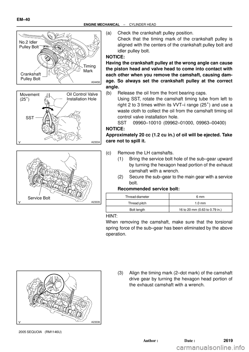
(a) Check the crankshaft pulley position.
Check that the timing mark of the crankshaft pulley is
aligned with the centers of the crankshaft pulley bolt and
idler pulley bolt.
NOTICE:
Having the crankshaft pulley at the wrong angle can cause
the piston head and valve head to come into contact with
each other when you remove the camshaft, causing dam-
age. So always set the crankshaft pulley at the correct
angle.
(b) Release the oil from the front bearing caps.
Using SST, rotate the camshaft timing tube from left to
right 2 to 3 times within its VVT±i range (25°) and use a
waste cloth to collect the oil from the camshaft timing oil
control valve installation hole.
SST 09960±10010 (09962±01000, 09963±00400)
NOTICE:
Approximately 20 cc (1.2 cu in.) of oil will be ejected. Take
care not to spill it.
(c) Remove the LH camshafts.
(1) Bring the service bolt hole of the sub±gear upward
by turning the hexagon head portion of the exhaust
camshaft with a wrench.
(2) Secure the sub±gear to the main gear with a service
bolt.
Recommended service bolt:
Thread diameter6 mm
Thread pitch1.0 mm
Bolt length16 to 20 mm (0.63 to 0.79 in.)
HINT:
When removing the camshaft, make sure that the torsional
spring force of the sub±gear has been eliminated by the above
operation.
(3) Align the timing mark (2±dot mark) of the camshaft
drive gear by turning the hexagon head portion of
the exhaust camshaft with a wrench.
Page 2628 of 4323

A23337
12
345
6
7
811
12 13
14
15
1617
18 2122
910 1920
A23338
Service Bolt
A23339
Approx.
10°
A23340
1 2
21
22
19 20
7
8 11
12
13
14
15
16
3
4 17
18
5
6 9
10
± ENGINE MECHANICALCYLINDER HEAD
EM±41
2620 Author�: Date�:
2005 SEQUOIA (RM1146U)
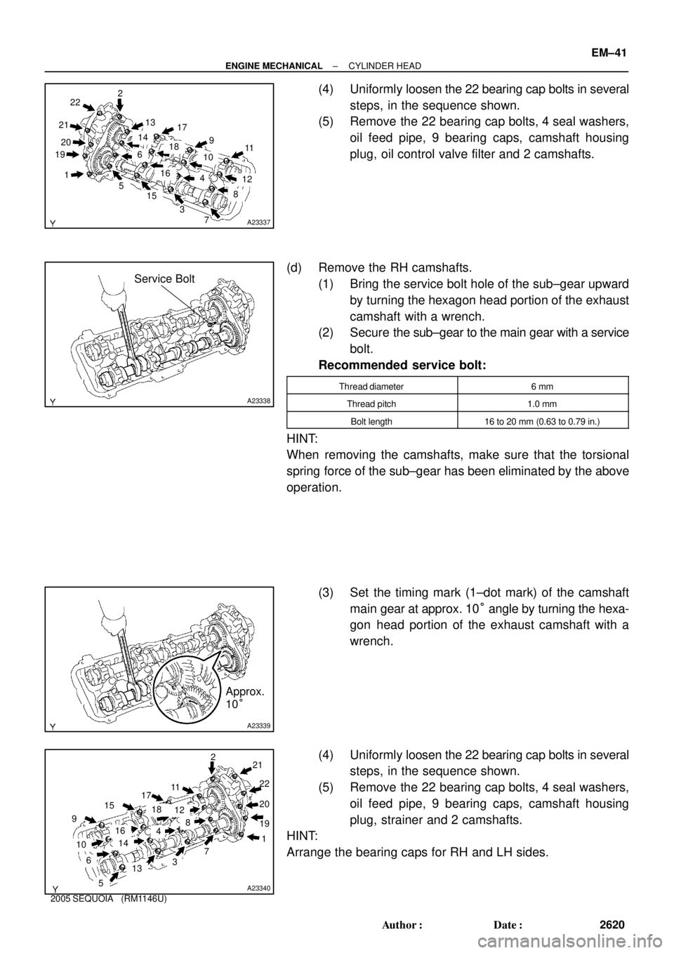
(4) Uniformly loosen the 22 bearing cap bolts in several
steps, in the sequence shown.
(5) Remove the 22 bearing cap bolts, 4 seal washers,
oil feed pipe, 9 bearing caps, camshaft housing
plug, oil control valve filter and 2 camshafts.
(d) Remove the RH camshafts.
(1) Bring the service bolt hole of the sub±gear upward
by turning the hexagon head portion of the exhaust
camshaft with a wrench.
(2) Secure the sub±gear to the main gear with a service
bolt.
Recommended service bolt:
Thread diameter6 mm
Thread pitch1.0 mm
Bolt length16 to 20 mm (0.63 to 0.79 in.)
HINT:
When removing the camshafts, make sure that the torsional
spring force of the sub±gear has been eliminated by the above
operation.
(3) Set the timing mark (1±dot mark) of the camshaft
main gear at approx. 10° angle by turning the hexa-
gon head portion of the exhaust camshaft with a
wrench.
(4) Uniformly loosen the 22 bearing cap bolts in several
steps, in the sequence shown.
(5) Remove the 22 bearing cap bolts, 4 seal washers,
oil feed pipe, 9 bearing caps, camshaft housing
plug, strainer and 2 camshafts.
HINT:
Arrange the bearing caps for RH and LH sides.
Page 2629 of 4323

A02859
A02850
SST
Service Bolt
Turn
A02861
A23341
Do Not Remove
A23342
10 mm
Hexagon
Wrench
EM±42
± ENGINE MECHANICALCYLINDER HEAD
2621 Author�: Date�:
2005 SEQUOIA (RM1146U)
25. DISASSEMBLE EXHAUST CAMSHAFTS
(a) Mount the hexagon head portion of the camshaft in a vise.
NOTICE:
Be careful not to damage the camshaft.
(b) Using SST, turn the sub±gear clockwise, and remove the
service bolt.
SST 09960±10010 (09962±01000, 09963±00500)
(c) Using snap ring pliers, remove the snap ring.
(d) Remove the wave washer.
(e) Remove the camshaft sub±gear.
(f) Remove the camshaft gear spring.
NOTICE:
Be careful not to damage the camshaft.
26. REMOVE CAMSHAFT TIMING TUBE FROM INTAKE
CAMSHAFT
(a) Mount the hexagon head portion of the intake camshaft
in a vise.
NOTICE:
�Be careful not to damage the camshaft.
�The 4 bolts shown in the illustration determine back-
lash of the gear in the timing tube, so do not remove
them. If any of the 4 bolts are removed, install a new
timing tube assembly.
(b) Remove the screw plug and seal washer.
(c) Using a 10 mm hexagon wrench, and remove the bolt.
(d) Pull out the timing tube and drive gear assembly from the
camshaft.