Page 3401 of 4592
(1)(3) Type B
± SFI (1MZ±FE)FUEL PUMP
SF±13
1512 Author�: Date�:
DISASSEMBLY
1. DISCONNECT FUEL PUMP CONNECTOR")
SF07C±03
S06028
Type B
S04603Pull Type A
S06033
PushA Type B
S06050
Type B
S06030
(2)(1)(3) Type B
± SFI (1MZ±FE)FUEL PUMP
SF±13
1512 Author�: Date�:
DISASSEMBLY
1. DISCONNECT FUEL PUMP CONNECTOR
2. TYPE B:
DISCONNECT GROUND PLATE
3. TYPE B:
DISCONNECT FUEL SENDER GAUGE CONNECTOR
4. Type A:
REMOVE FUEL PUMP FROM FUEL PUMP BRACKET
(a) Pull off the lower side of the fuel pump from the pump
bracket.
(b) Disconnect the fuel hose from the fuel pump, and remove
the fuel pump.
(c) Remove the rubber cushion from the fuel pump.
5. Type B:
REMOVE FUEL SENDER GAUGE
Push down the portion of A with a finger, and push up the send-
er gauge.
NOTICE:
Be careful that the arm of the sender gauge should not
bent.
6. Type B:
REMOVE FUEL FILTER
(a) Remove the screw, and pull out the fuel filter.
(b) Remove the O±ring from the fuel filter.
HINT:
At the time of installation, please refer to the following items.
Install the pump filter with a new clip.
7. TYPE B:
REMOVE FUEL PUMP FLANGE
Using a screwdriver, remove the snap fit portion in the order of
1, 2 and 3 as shown in the illustration.
HINT:
At the time of installation, please refer to the following items. Ap-
ply a light coat of gasoline to a new O±ring, and install it to the
fuel filter.
Page 3407 of 4592
SF07G±03
S04591
S04590
± SFI (1MZ±FE)FUEL PRESSURE REGULATOR
SF±19
1518 Author�: Date�:
REMOVAL
1. REMOVE FUEL PUMP ASSEMBLY FROM FUEL TANK
(See page SF±12)
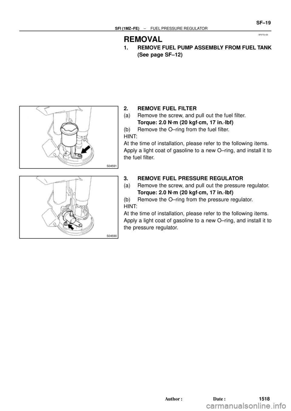
2. REMOVE FUEL FILTER
(a) Remove the screw, and pull out the fuel filter.
Torque: 2.0 N´m (20 kgf´cm, 17 in.´lbf)
(b) Remove the O±ring from the fuel filter.
HINT:
At the time of installation, please refer to the following items.
Apply a light coat of gasoline to a new O±ring, and install it to
the fuel filter.
3. REMOVE FUEL PRESSURE REGULATOR
(a) Remove the screw, and pull out the pressure regulator.
Torque: 2.0 N´m (20 kgf´cm, 17 in.´lbf)
(b) Remove the O±ring from the pressure regulator.
HINT:
At the time of installation, please refer to the following items.
Apply a light coat of gasoline to a new O±ring, and install it to
the pressure regulator.
Page 3416 of 4592
SF07M±04
B00629
California A/T
Except California A/TNew Insulator
New Grommet New
O±RingNew
O±Ring
New Grommet
New Insulator
New
O±RingNew
O±Ring
B00625
Turn
Connector
Push
Turn
Connector
Push
California A/T
Except California A/T
S04510
Spacer
Spacer SF±28
± SFI (1MZ±FE)INJECTOR
1527 Author�: Date�:
INSTALLATION
1. INSTALL INJECTORS AND DELIVERY PIPES
(a) Install new insulator and grommet to each injector.
(b) Apply a light coat of spindle oil or gasoline to 2 new O±
rings and install them to each injector.
(c) Apply a light coat of spindle oil or gasoline on the place
where a delivery pipe touches an O±ring of the injector.
(d) While turning the injector clockwise and counterclock-
wise, push it to the delivery pipes. Install the 6 injectors.
(e) Position the injector connector outward.
(f) Place the 4 spacers in position on the intake manifold.
Page 3417 of 4592
INJECTOR
SF±29
1528 Author�: Date�:
(g) Apply a light coat of spindle oil or gasoline on the place
where a intake manifold touc")
B01021
S04728
Rotate
Outward
B01020
S06525
Align
S05351
± SFI (1MZ±FE)INJECTOR
SF±29
1528 Author�: Date�:
(g) Apply a light coat of spindle oil or gasoline on the place
where a intake manifold touches an O±ring of the injector.
(h) Place the delivery pipes and fuel pipe together with the 6
injectors in position on the intake manifold.
(i) Temporarily install the 4 bolts holding the delivery pipes
to the intake manifold.
(j) Temporarily install the bolt holding the No.1 fuel pipe to
the intake manifold.
(k) Check that the injectors rotate smoothly.
HINT:
If injectors do not rotate smoothly, the probable cause is incor-
rect installation of O±rings. Replace the O±rings.
(l) Position the injector connector outward.
(m) Tighten the 4 bolts holding the delivery pipes to the intake
manifold.
Torque: 10 N´m (100 kgf´cm, 7 ft´lbf)
(n) Tighten the bolt holding the No.1 fuel pipe to the intake
manifold.
Torque: 19.5 N´m (200 kgf´cm, 14 ft´lbf)
2. CONNECT NO.1 FUEL PIPE
(a) Align the alignment marks (white paint) on the No.1 fuel
pipe.
(b) Connect the No.1 fuel pipe (fuel tube connector) to the
fuel filter.
CAUTION:
Perform connecting operations of the fuel tube connector
(quick type) after observing the precaution.
(See page SF±1)
Page 3440 of 4592
SF087±03
B06468
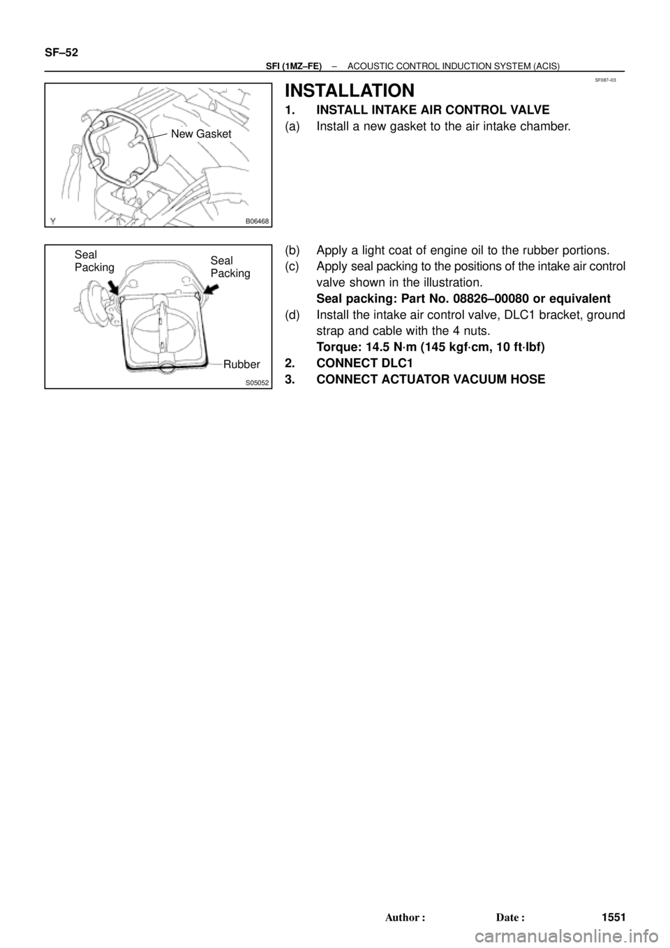
New Gasket
S05052
Seal
Packing
Rubber Seal
Packing SF±52
± SFI (1MZ±FE)ACOUSTIC CONTROL INDUCTION SYSTEM (ACIS)
1551 Author�: Date�:
INSTALLATION
1. INSTALL INTAKE AIR CONTROL VALVE
(a) Install a new gasket to the air intake chamber.
(b) Apply a light coat of engine oil to the rubber portions.
(c) Apply seal packing to the positions of the intake air control
valve shown in the illustration.
Seal packing: Part No. 08826±00080 or equivalent
(d) Install the intake air control valve, DLC1 bracket, ground
strap and cable with the 4 nuts.
Torque: 14.5 N´m (145 kgf´cm, 10 ft´lbf)
2. CONNECT DLC1
3. CONNECT ACTUATOR VACUUM HOSE
Page 3514 of 4592
R07653
SR06G±01
F01477
SR±8
± STEERINGSTEERING WHEEL
2103 Author�: Date�:
STEERING WHEEL
INSPECTION
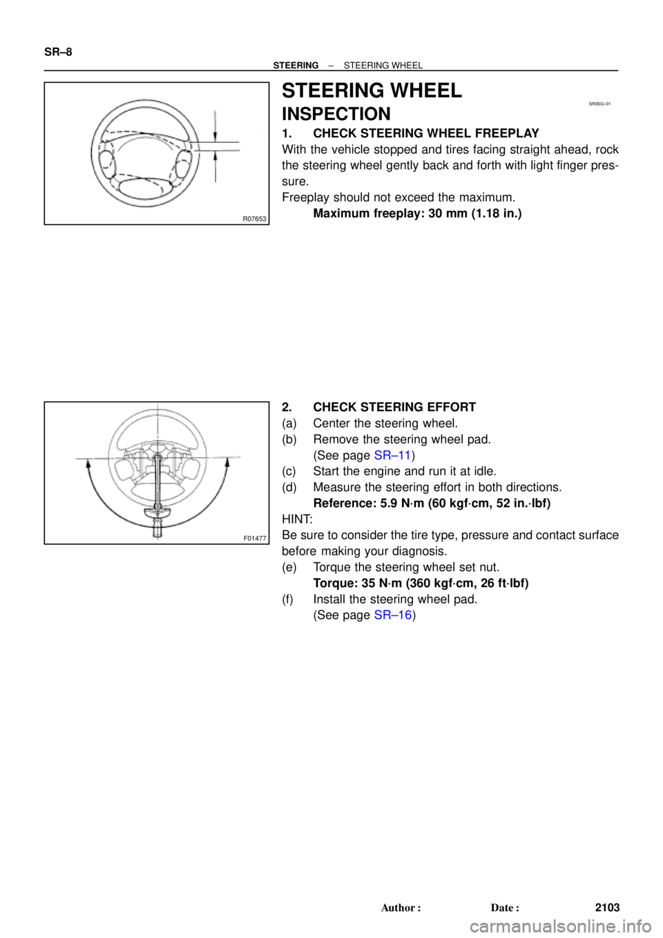
1. CHECK STEERING WHEEL FREEPLAY
With the vehicle stopped and tires facing straight ahead, rock
the steering wheel gently back and forth with light finger pres-
sure.
Freeplay should not exceed the maximum.
Maximum freeplay: 30 mm (1.18 in.)
2. CHECK STEERING EFFORT
(a) Center the steering wheel.
(b) Remove the steering wheel pad.
(See page SR±11)
(c) Start the engine and run it at idle.
(d) Measure the steering effort in both directions.
Reference: 5.9 N´m (60 kgf´cm, 52 in.´lbf)
HINT:
Be sure to consider the tire type, pressure and contact surface
before making your diagnosis.
(e) Torque the steering wheel set nut.
Torque: 35 N´m (360 kgf´cm, 26 ft´lbf)
(f) Install the steering wheel pad.
(See page SR±16)
Page 3656 of 4592
 May 16, 1997
The following precautions should be taken to keep cassettes in good condition:
1. Remove the cassette from the player when")
CLEANING CASSETTE TAPE HEADSAND CAPSTANS ± AU001±97 (Revised) May 16, 1997
The following precautions should be taken to keep cassettes in good condition:
1. Remove the cassette from the player when the cassette is not in use.
2. Store the cassette in its case.
3. Store the cassette in a cool, dry area away from direct sunlight and magnetic
components such as speakers.
4. Avoid touching the tape itself. This could result in poor sound quality or sound drop out.
5. Keep the tape tightly wound as shown in
figure 2. Tape speed can be affected by
loosely wound tape.
6. Avoid inserting a cassette into the player if
the cassette label is loose or peeling as
shown in figure 3. This can cause a
cassette to become stuck in the player.
7. Use cassettes that are 90 minutes or
less in length. Cassettes over 90
minutes use extremely thin tape that is
subject to stretch, resulting in poor
sound quality.
Page 2 of 2
Cassette
Tape Care
Procedure
Peeling Label
Use a pencil
to tighten up
loose tapes.
Tape length
in minutes
Fig. 2
Fig. 3
Fig. 4
Page 3662 of 4592

Toyota Supports ASE CertificationPage 1 of 2
AX003±00Title:
PORT INSTALLED RS3000 TVIP TRUNK
COURTESY CONNECTION
Models:
'99 Camry
Technical Service
BULLETIN
March 31, 2000
The trunk courtesy connection for 1999 model year Camry vehicles equipped with a Port
Installed Option RS3000 (V3) has been relocated from the luggage compartment light
switch to below the dash (lower finish panel) on the driver's side in the Instrument Panel
J/B. (Refer to Illustrations A & B on page 2.)
�The location was changed to improve the installation process.
�A splicing connector is used for the new trunk courtesy wire installation (blue) to the
vehicle's wire harness at Instrument Panel J/B (red/yellow).
�The previous location is the same as the dealer installed RS3000 trunk courtesy
connection to the luggage compartment light switch connection.
For service related purposes, this bulletin describes the procedures to locate the new
trunk courtesy connection at Instrument Panel J/B in vehicles equipped with PIO
RS3000.
�The remote transmitter has two
buttons, Top and Bottom.�The status monitor has a Toyota label,
LED, and microphone.
Remote Control
LED
Status Monitor
Microphone
�1999 model year Camry vehicles equipped with PIO (V3) TVIP.
OP CODEDESCRIPTIONTIMEOPNT1T2
N/ANot Applicable to Warranty ±±±±
ACCESSORIES
Introduction
Applicable
Vehicles
Warranty
Information