Page 3187 of 4592

R05403
R09690
Battery
SSTFront Passenger
Airbag Assembly
10 m (33 ft) or more
± SUPPLEMENTAL RESTRAINT SYSTEMFRONT PASSENGER AIRBAG ASSEMBLY
RS±35
2180 Au")
AB0158
Battery
SST
H04528
Tires
(5 or more)
R05403
R09690
Battery
SSTFront Passenger
Airbag Assembly
10 m (33 ft) or more
± SUPPLEMENTAL RESTRAINT SYSTEMFRONT PASSENGER AIRBAG ASSEMBLY
RS±35
2180 Author�: Date�:
(c) Check functioning of the SST.
SST 09082±00700
(d) Place tires.
(1) Place at least 2 tires under the tire to which the front
passenger airbag assembly is tied.
(2) Place at least 2 tires over the tire to which the front
passenger airbag assembly is tied. The top tire
should have the wheel installed.
(3) Tie the tires together with 2 wire harness.
CAUTION:
Make sure that the wire harness is tight. It is very danger-
ous if loose wire harness result in the tires coming free due
to the shock from the airbag deploying.
HINT:
Place the SST connector and wire harness inside tires. Provide
at least 1 m (3 ft) of slack for the wire harness.
(e) Install the SST.
Connect the connector of 2 SST to the front passenger
airbag assembly connector.
SST 09082±00700, 09082±00760
NOTICE:
To avoid damaging the SST connector and wire harness,
do not lock the secondary lock of the twin lock.
(f) Deploy the airbag.
(1) Connect the SST red clip to the battery positive (+)
terminal and the black clip to the battery negative
(±) terminal.
(2) Check that no one is within 10 m (33 ft) area around
the tire which the front passenger airbag assembly
is tied to.
(3) Press the SST activation switch and deploy the air-
bag.
HINT:
The airbag deploys simultaneously as the LED of the SST ac-
tivation switch lights up.
Page 3195 of 4592
 or more
H01326
± SUPPLEMENTAL RESTRAINT SYSTEMSIDE AIRBAG ASSEMBLY (TMC Made)
RS±43
2188 Author�: Date�:
1. AIRBAG DEPLOYMENT WHEN SC")
AB0158
Battery
SST
H01353
H01354
Battery
SST
R13455
10 m (33 ft) or more
H01326
± SUPPLEMENTAL RESTRAINT SYSTEMSIDE AIRBAG ASSEMBLY (TMC Made)
RS±43
2188 Author�: Date�:
1. AIRBAG DEPLOYMENT WHEN SCRAPPING VE-
HICLE
HINT:
Have a battery ready as the power source to deploy the airbag.
(a) Check functioning of the SST. (See page RS±18)
SST 09082±00700
(b) Disconnect the side airbag connector.
NOTICE:
When handling the airbag connector, take care not to dam-
age the airbag wire harness.
(c) Install the SST.
(1) Connect the connector of 2 SST to the airbag con-
nector.
SST 09082±00700, 09082±00750
NOTICE:
To avoid damaging the SST connector and wire harness,
do not lock the secondary lock of the twin lock.
(2) Move the SST at least 10 m (33 ft) away from the
front of the vehicle.
(3) Close all the doors and windows of the vehicle.
NOTICE:
Take care not to damage the SST wire harness.
(4) Connect the SST red clip to the battery positive (+)
terminal and the black clip to the battery negative
(±) terminal.
(d) Deploy the airbag.
(1) Check that no one is inside the vehicle or within 10
m (33 ft) area around the vehicle.
(2) Press the SST activation switch and deploy the air-
bag.
HINT:
The airbag deploys simultaneously as the LED of SST activa-
tion switch lights up.
Page 3198 of 4592

R05403
H0133710 m (33 ft) or more SSTBattery
Side Airbag
Assembly
H00544
RS±46
± SUPPLEMENTAL RESTRAINT SYSTEMSIDE AIRBAG ASSEMBLY (TMC Made)
2191 Author�: Date�:
(e) Place")
H01336
Tires
(5 or More)
R05403
H0133710 m (33 ft) or more SSTBattery
Side Airbag
Assembly
H00544
RS±46
± SUPPLEMENTAL RESTRAINT SYSTEMSIDE AIRBAG ASSEMBLY (TMC Made)
2191 Author�: Date�:
(e) Place the tires.
(1) Place at least 2 tires under the tire to which the side
airbag assembly is tied.
(2) Place at least 2 tires over the tire to which the side
airbag assembly is tied. The top tire should have the
wheel installed.
(3) Tie the tires together with the 2 wire harnesses.
CAUTION:
Make sure that the wire harnesses are tight. It is very dan-
gerous when loose wire harnesses result in the tires com-
ing free due to the shock from the airbag deploying.
HINT:
Place the SST connector and wire harness inside tires. Secure
at least 1 m (3 ft) of slack for the wire harness.
(f) Install the SST.
Connect the connector of 2 SST to the side airbag assem-
bly connector.
SST 09082±00700, 09082±00750
(g) Deploy the airbag.
(1) Connect the SST red clip to the battery positive (+)
terminal and the black clip to the battery negative
(±) terminal.
(2) Check that no one is within 10 m (33 ft) area around
the tire which the side airbag assembly is tied to.
(3) Press the SST activation switch and deploy the air-
bag.
HINT:
The airbag deploys simultaneously as the LED of the SST ac-
tivation switch lights up.
(h) Dispose of the side airbag assembly.
CAUTION:
�The side airbag assembly is very hot when the airbag
is deployed, so leave it alone for at least 30 minutes
after deployment.
�Use gloves and safety glasses when handling a side
airbag assembly with the deployed airbag.
�Do not apply water etc. to a side airbag assembly with
the deployed airbag.
Page 3215 of 4592
RS01L±14
H08233
N´m (kgf´cm, ft´lbf) : Specified torqueFront Airbag Sensor (RH)Front Airbag Sensor (LH)
20 (205, 15)
20 (205, 15)
20 (205, 15)
Turn Signal Light RH
Turn Signal Light LH
Head Light RH
Head Light LH
± SUPPLEMENTAL RESTRAINT SYSTEMFRONT AIRBAG SENSOR
RS±63
2208 Author�: Date�:
FRONT AIRBAG SENSOR
COMPONENTS
Page 3216 of 4592
RS0F0±01
H08318
H08319
RS±64
± SUPPLEMENTAL RESTRAINT SYSTEMFRONT AIRBAG SENSOR
2209 Author�: Date�:
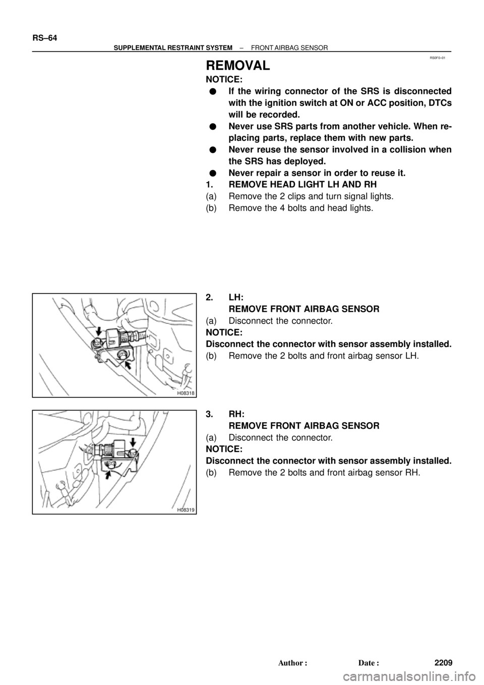
REMOVAL
NOTICE:
�If the wiring connector of the SRS is disconnected
with the ignition switch at ON or ACC position, DTCs
will be recorded.
�Never use SRS parts from another vehicle. When re-
placing parts, replace them with new parts.
�Never reuse the sensor involved in a collision when
the SRS has deployed.
�Never repair a sensor in order to reuse it.
1. REMOVE HEAD LIGHT LH AND RH
(a) Remove the 2 clips and turn signal lights.
(b) Remove the 4 bolts and head lights.
2. LH:
REMOVE FRONT AIRBAG SENSOR
(a) Disconnect the connector.
NOTICE:
Disconnect the connector with sensor assembly installed.
(b) Remove the 2 bolts and front airbag sensor LH.
3. RH:
REMOVE FRONT AIRBAG SENSOR
(a) Disconnect the connector.
NOTICE:
Disconnect the connector with sensor assembly installed.
(b) Remove the 2 bolts and front airbag sensor RH.
Page 3219 of 4592
 Install the front airbag sensor with")
RS01P±14
H06728
LH:
RH:
± SUPPLEMENTAL RESTRAINT SYSTEMFRONT AIRBAG SENSOR
RS±67
2212 Author�: Date�:
INSTALLATION
1. INSTALL FRONT AIRBAG SENSOR LH AND RH
(a) Install the front airbag sensor with the arrow on the sensor
facing toward the front of the vehicle.
Torque: 20 N´m (205 kgf´cm, 15 ft´lbf)
NOTICE:
�Connection of the connector is done after the sensor
assembly has been installed.
�Make sure the sensor is installed with the specified
torque.
�If the sensor has been dropped, or there are cracks,
dents or other defects in the case, brackets or con-
nector, replace the removed sensor with a new one.
�The front sensor is equipped with an electrical con-
nection check mechanism. Be sure to lock this mech-
anism securely when connecting the connector. If the
connector is not securely locked, a malfunction code
will be detected by the diagnostic system.
(b) Connect the front airbag sensor connector.
2. INSTALL HEAD LIGHT LH AND RH
(See page BE±28)
3. INSTALL TURN SIGNAL LIGHT LH AND RH
Page 3225 of 4592
RS01V±11
H08282
Spiral CableCombination Meter
(Warning Light)Front Passenger Airbag Assembly
Side Airbag Assembly (RH)
Side Airbag Sensor
Assembly (RH)
Seat Belt Pretensioner (RH) Steering Wheel Pad
(with Airbag)
Side Airbag Sensor
Assembly (LH)
Seat Belt Pretensioner (LH)
Side Airbag Assembly (LH)
Airbag Sensor Assembly
Front Airbag Sensor (RH)
Front Airbag
Sensor (LH)
± SUPPLEMENTAL RESTRAINT SYSTEMWIRE HARNESS AND CONNECTOR
RS±73
2218 Author�: Date�:
WIRE HARNESS AND CONNECTOR
LOCATION
Page 3287 of 4592
± SERVICE SPECIFICATIONSMANUAL TRANSAXLE (E153)
SS±49
212 Author�: Date�:
Transmission oil pump assembly x Transaxle case1717513
Transaxle case receiver x Transaxle case7.47565 in.´lbf
Clutch release fork support4748035
Control lever housing support bracket x Transaxle case1717513
Vehicle speed sensor1717513
Clutch release line bracket x Transaxle case1717513
Back±up light switch4041030
Filler and drain plug4950036
No.1 and No.2 oil receiver pipe x Transmission case1717513
Transmission oil cooler sub±assembly x Elbow3435025
Elbow x Transaxle case2727520
Transmission oil pump case x Oil pump cover101058
Transaxle case cover x Transaxle case5455040
Differential left case x Differential right case6364046
Ring gear set bolt1241,26091
 : Specified torqueFront Airbag Sensor (RH)Front Airbag Sensor (LH)
20 (205, 15)
20 (205, 15)
20 (205, 15)
Turn Signal Light RH
Turn Signal Light LH
Head Light")
Front Passenger Airbag Assembly
Side Airbag Assembly (RH)
Side Airbag Sensor
Assembly (RH)
Seat Belt Pretensioner (RH) Steering Wheel Pad")