Page 2991 of 4592

MX04F±02
Z19123
Transmission Case Cover5th Driven GearRear Bearing Retainer
No.3 Shift Fork N0.3 Hub Sleeve No.3 Clutch Hub Assembly Needle Roller BearingRelease ForkTransmission
CaseDifferential Side
Bearing Retainer
Transmission
Case Protector Straight Screw Plug
Shift and Select Lever
Assembly
Selecting Bellcrank Back±UP
Light SwitchLock Ball
Assembly Release Bearing
Retainer
Vehicle
Speed Sensor
Release
BearingReverse
Restrict Pin�
O±Ring �Shim
x 6 Slotted
Spring Pin
Gasket
Clutch Release Fork
Support
x 17
Snap RingLock Nut Filler Plug
Lock Boltx 5
Spacer
5th Gear
x 8 Boot
�
Gasket �
Gasket �Drain Plug
Snap Ring�
�
�
� �Non±reusable part
Precoated part: Specified torque
N´m (kgf´cm, ft´lbf)
5.4 (55, 48 in.´lbf)
13 (130, 9)
123 (1,250, 90)�
37 (375, 27)29 (300, 22)�
44 (450, 33)
18 (185, 13)
18 (185, 13)
42 (430, 31)
29 (300, 22)
29 (300, 22)
49 (500, 36)
39 (400, 29)
18 (185, 13)
29 (300, 22)
7.4 (75, 65 in.´lbf)
37 (380, 27)
± MANUAL TRANSAXLE (S51)MANUAL TRANSAXLE ASSEMBLY
MX±9
1859 Author�: Date�:
MANUAL TRANSAXLE ASSEMBLY
COMPONENTS
Page 2993 of 4592
MANUAL TRANSAXLE ASSEMBLY
MX±11
1861 Author�: Date�:
DISASSEMBLY
1. REMOVE RELEASE FORK AND BEARING
2. REMOVE BACK±UP LIGHT SWITCH
Torque: 44 N´m (450")
MX04G±02
Z18142FIPG
± MANUAL TRANSAXLE (S51)MANUAL TRANSAXLE ASSEMBLY
MX±11
1861 Author�: Date�:
DISASSEMBLY
1. REMOVE RELEASE FORK AND BEARING
2. REMOVE BACK±UP LIGHT SWITCH
Torque: 44 N´m (450 kgf´cm, 33 ft´lbf)
3. REMOVE BOLT AND VEHICLE SPEED SENSOR
Torque: 5.4 N´m (55 kgf´cm, 48 in.´lbf)
4. REMOVE RELEASE BEARING RETAINER
Remove the 3 bolts and retainer.
Torque: 7.4 N´m (75 kgf´cm, 65 in.´lbf)
5. REMOVE SELECTING BELLCRANK
Remove the 2 bolts and selecting bellcrank.
Torque: 37 N´m (380 kgf´cm, 27 ft´lbf)
6. REMOVE TRANSMISSION CASE COVER
(a) Remove the 8 bolts.
Sealant:
Part No.08833 ± 00080, THREE BOND 1344, LOCTITE
242 or equivalent
Torque: 29 N´m (300 kgf´cm, 22 ft´lbf)
(b) Using a plastic hammer, tap the transmission case cover
and remove it.
FIPG:
Part No. 08826 ± 00090, THREE BOND 1281 or equiva-
lent
7. REMOVE LOCK BALL ASSEMBLY
Sealant:
Part No.08833 ± 00080, THREE BOND 1344, LOCTITE
242 or equivalent
Torque: 29 N´m (300 kgf´cm, 22 ft´lbf)
8. REMOVE SHIFT AND SELECT LEVER ASSEMBLY
HINT:
At the time of installation, please refer to the following item.
Apply FIPG to the underside of the flanged portion of the control
shaft cover.
FIPG:
Part No. 08826 ± 00090, THREE BOND 1281 or equiva-
lent
Torque: 37 N´m (375 kgf´cm, 27 ft´lbf)
Page 3005 of 4592
INPUT SHAFT
MX±23
1873 Author�: Date�:
INSPECTION
1. INSPECT SYNCHRONIZER RING
(a) Check for wear or damage.
(b) Check the braking effect of th")
MX04L±01
WM0064
WM0065
WM0066
± MANUAL TRANSAXLE (S51)INPUT SHAFT
MX±23
1873 Author�: Date�:
INSPECTION
1. INSPECT SYNCHRONIZER RING
(a) Check for wear or damage.
(b) Check the braking effect of the synchronizer ring. Turn the
synchronizer ring in one direction while pushing it to the
gear cone. Check that the ring locks.
If the braking effect is insufficient, apply a small amount of the
fine lapping compound between the synchronizer ring and gear
cone. Lightly rub the synchronizer ring and gear cone together.
NOTICE:
Ensure the fine lapping compound is completely washed
off after rubbing.
(c) Check again the braking effect of the synchronizer ring.
(d) Using a feeler gauge, measure the clearance between
the synchronizer ring back and gear spline end.
Minimum clearance:
0.6 mm (0.024 in.)
If the clearance is less than the minimum, replace the synchro-
nizer ring, and apply a small amount of the fine lapping com-
pound on gear cone.
NOTICE:
Ensure the fine lapping compound is completely washed
off after rubbing.
2. INSPECT NO.2 SHIFT FORK AND HUB SLEEVE
CLEARANCE
Using a feeler gauge, measure the clearance between the hub
sleeve and shift fork.
Maximum clearance:
1.0 mm (0.039 in.)
If the clearance exceeds the maximum, replace shift fork or hub
sleeve.
Page 3013 of 4592
OUTPUT SHAFT
MX±31
1881 Author�: Date�:
INSPECTION
1. INSPECT 1ST GEAR SYNCHRONIZER RING
(a) Check for wear or damage.
(b) Check the bra")
MX04P±01
WM0064
WM0065
MT0780
MT0787
± MANUAL TRANSAXLE (S51)OUTPUT SHAFT
MX±31
1881 Author�: Date�:
INSPECTION
1. INSPECT 1ST GEAR SYNCHRONIZER RING
(a) Check for wear or damage.
(b) Check the braking effect of the synchronizer ring. Turn the
synchronizer ring in one direction while pushing it to the
gear cone. Check that the ring locks.
If the braking effect is insufficient, apply a small amount of the
fine lapping compound between the synchronizer ring and gear
cone. Lightly rub the synchronizer ring and gear cone together.
NOTICE:
Ensure the fine lapping compound is completely washed
off after rubbing.
(c) Check again the braking effect of the synchronizer ring.
(d) Using a feeler gauge, measure the clearance between
the synchronizer ring back and the gear spline end.
Minimum clearance:
0.6 mm (0.024 in.)
If the clearance is less than the minimum, replace the synchro-
nizer ring, and apply a small amount of the fine lapping com-
pound on gear cone.
NOTICE:
Ensure the fine lapping compound is completely washed
off after rubbing.
2. INSPECT 2ND GEAR SYNCHRONIZER RING
(a) Check for wear or damage.
(b) Check the braking effect of the synchronizer ring.
Turn the synchronizer ring in one direction while pushing
it to the gear cone. Check that the ring locks.
If the braking effect is insufficient, replace the synchronizer ring.
(c) Using a feeler gauge, measure the clearance between
the synchronizer ring back and gear spline end.
Minimum clearance:
0.7 mm (0.028 in.)
If the clearance is less than the minimum, replace the synchro-
nizer ring.
Page 3045 of 4592
PP1WW±01
PP±20
± PREPARATIONSFI (1MZ±FE)
72 Author�: Date�:
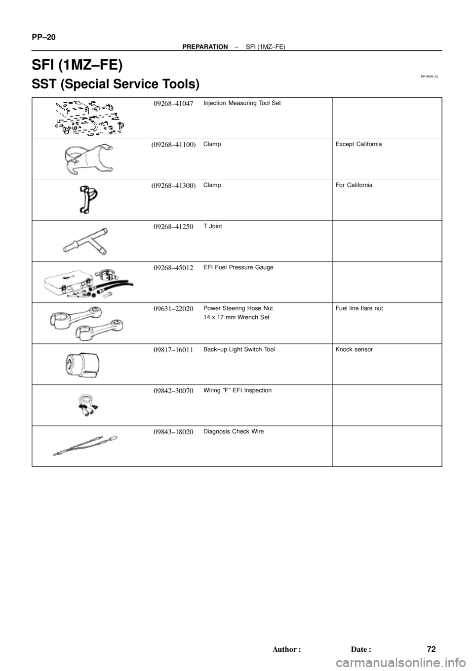
SFI (1MZ±FE)
SST (Special Service Tools)
09268±41047Injection Measuring Tool Set
(09268±41100)ClampExcept California
(09268±41300)ClampFor California
09268±41250T Joint
09268±45012EFI Fuel Pressure Gauge
09631±22020Power Steering Hose Nut
14 x 17 mm Wrench SetFuel line flare nut
09817±16011Back±up Light Switch ToolKnock sensor
09842±30070Wiring ºFº EFI Inspection
09843±18020Diagnosis Check Wire
Page 3130 of 4592
PP0MV±01
± PREPARATIONBODY
PP±105
157 Author�: Date�:
EQUIPMENT
Clip remover
Torque wrench
Drill
Drill bit, diam 3.2 mm (0.126 in.)
Hand riveter
TapeTo avoid surface damage
Adhesive tapeTo avoid surface damage
Adhesive
Cleaner
Shop ragRegulator handle
Water pump pliersWindow regulator
KnifeMoulding
Heat lightMoulding
Piano wireWindshield
Rope (no projections, difficult to break)Seat belt pretensioner disposal
Tire Width: 185 mm (7.28 in.)
Inner diam: 360 mm (14.17 in.)Seatbelt pretensioner disposal
Tire with disc wheel Width: 185 mm (7.28 in.)
Inner diam 360 mm (14.17 in.)Seat belt pretinsioner disposal
Vinyl bagSeat belt pretensioner disposal
Page 3153 of 4592

RS01Y±22
± SUPPLEMENTAL RESTRAINT SYSTEMSRS AIRBAG
RS±1
2146 Author�: Date�:
SRS AIRBAG
PRECAUTION
NOTICE:
�The CAMRY is equipped with SRS, which comprises a driver airbag, front passenger airbag,
and side airbag. Failure to carry out service operations in the correct sequence could cause
the SRS to unexpectedly deploy during servicing, possibly leading to a serious accident. Fur-
ther, if a mistake is made in servicing the SRS, it is possible that the SRS may fail to operate
when required. Before performing servicing (including removal or installation of parts, inspec-
tion or replacement), be sure to read the following items carefully, then follow the correct proce-
dures described in the repair manual.
�Malfunction symptoms of the SRS are difficult to confirm, so the DTCs become the most impor-
tant source of information when troubleshooting. When troubleshooting the SRS, always in-
spect the DTCs before disconnecting the battery.
�Even in cases of a minor collision where the SRS does not deploy, the steering wheel pad, front
passenger airbag assembly, side airbag assembly (TMC made and TMMK made), airbag sensor
assembly, front airbag sensor and side airbag sensor assembly should be inspected.
(See page RS±16, RS±29, RS±41, RS±54, RS±60, RS±65 and RS±70)
�Never use SRS parts from another vehicle. When replacing parts, replace them with new parts.
�Never disassemble and repair the steering wheel pad, front passenger airbag assembly, side
airbag assembly, airbag sensor assembly, front airbag sensor or side airbag sensor assembly
in order to reuse it.
�If the steering wheel pad, front passenger airbag assembly, side airbag assembly, airbag sen-
sor assembly, front airbag sensor or side airbag sensor assembly has been dropped, or if there
are cracks, dents or other defects in the case, bracket or connector, replace them with new
ones.
�Use a volt/ohmmeter with high impedance (10 kW/V minimum) for troubleshooting the system's
electrical circuits.
�Information labels are attached to the periphery of the SRS components. Follow the instruc-
tions on the notices.
�After work on the SRS is completed, perform the SRS warning light check (See page DI±626).
�If the vehicle is equipped with a mobile communication system, refer to the precaution in the
IN section.
CAUTION:
�Work must be started 90 seconds after the ignition switch is turned to the ºLOCKº position and
the negative (±) terminal cable is disconnected from the battery.
(The SRS is equipped with a back±up power source so that if work is started within 90 seconds
from disconnecting the negative (±) terminal cable of the battery, the SRS may be deployed.)
�When the negative (±) terminal cable is disconnected from the battery, the memory of the clock
and audio system will be canceled. So before starting work, make a record of the contents mem-
orized in the audio memory system. When work is finished, reset the audio systems as they
were before and adjust the clock. To avoid erasing the memory in each memory system, never
use a back± up power supply from outside the vehicle.
�Before repairs, remove the airbag sensor if shocks are likely to be applied to the sensor during
repairs.
�Do not expose the steering wheel pad, front passenger airbag assembly, side airbag assembly,
airbag sensor assembly, front airbag sensor or side airbag sensor assembly directly to hot air
or flames.
Page 3155 of 4592

H02309
H02266
H08235
H03284
± SUPPLEMENTAL RESTRAINT SYSTEMSRS AIRBAG
RS±3
2148 Author�: Date�:
6. SRS WARNING LIGHT
The SRS warning light is located on the combination meter. It
goes on to alert the driver of trouble in the system when a mal-
function is detected in the airbag sensor assembly self±diagno-
sis. In normal operation conditions when the ignition switch is
turned to the ACC or ON position, the light goes on for about 6
seconds and then goes off.
7. AIRBAG SENSOR ASSEMBLY
The airbag sensor assembly is mounted on the floor inside the
lower center finish panel. The airbag sensor assembly consists
of an airbag sensor, safing sensor, diagnosis circuit, ignition
control and drive circuit, etc. It receives signals from the airbag
sensor and judges whether the SRS must be activated or not.
8. FRONT AIRBAG SENSOR
A front airbag sensor is mounted inside each of the side mem-
bers. The sensor unit is a mechanical type. When the sensor
detects deceleration force above a predetermined limit, contact
is made in the sensor, sending a signal to the airbag sensor as-
sembly. The sensor cannot be disassembled.
9. SIDE AIRBAG SENSOR ASSEMBLY
The side airbag sensor assembly is mounted in the LH and RH
center pillars. The side airbag sensor assembly consists of a lat-
eral deceleration sensor, safing sensor and diagnosis circuit,
etc. It receives signals to the airbag sensor assembly to judge
from the side airbag sensors whether the SRS side airbag must
be activated or not.