Page 2882 of 4592

HSGHousing
HTHard Top
HWSHeated Windshield System
IACIdle Air Control
ICIntegrated circuit
IDIIndirect Diesel Inj")
IN±36
± INTRODUCTIONTERMS
36 Author�: Date�:
HIDHigh Intensity Discharge (Head Lamp)
HSGHousing
HTHard Top
HWSHeated Windshield System
IACIdle Air Control
ICIntegrated circuit
IDIIndirect Diesel Injection
IFSIndependent Front Suspension
IGIgnition
IIAIntegrated Ignition Assembly
INIntake (Manifold, Valve)
INTIntermittent
I/PInstrument Panel
IRSIndependent Rear Suspension
J/BJunction Block
J/CJunction Connector
KDKick±Down
LANLocal Area Network
LBLiftback
LCDLiquid Crystal Display
LEDLight Emitting Diode
LHLeft±Hand
LHDLeft±Hand Drive
L/H/WLength, Height, Width
LLCLong±Life Coolant
LNGLiquified Natural Gas
LOLow
LPGLiquified Petroleum Gas
LSDLimited Slip Differential
LSP & PVLoad Sensing Proportioning And Bypass Valve
LSPVLoad Sensing Proportioning Valve
MAX.Maximum
MICMicrophone
MILMalfunction Indicator Lamp
MIN.Minimum
MPMultipurpose
MPXMultiplex Communication System
M/TManual Transmission
MTMount
MTGMounting
NNeutral
NANatural Aspiration
No.Number
O/DOverdrive
OEMOriginal Equipment Manufacturing
OHCOverhead Camshaft
Page 2905 of 4592
LU03T±03
S05930
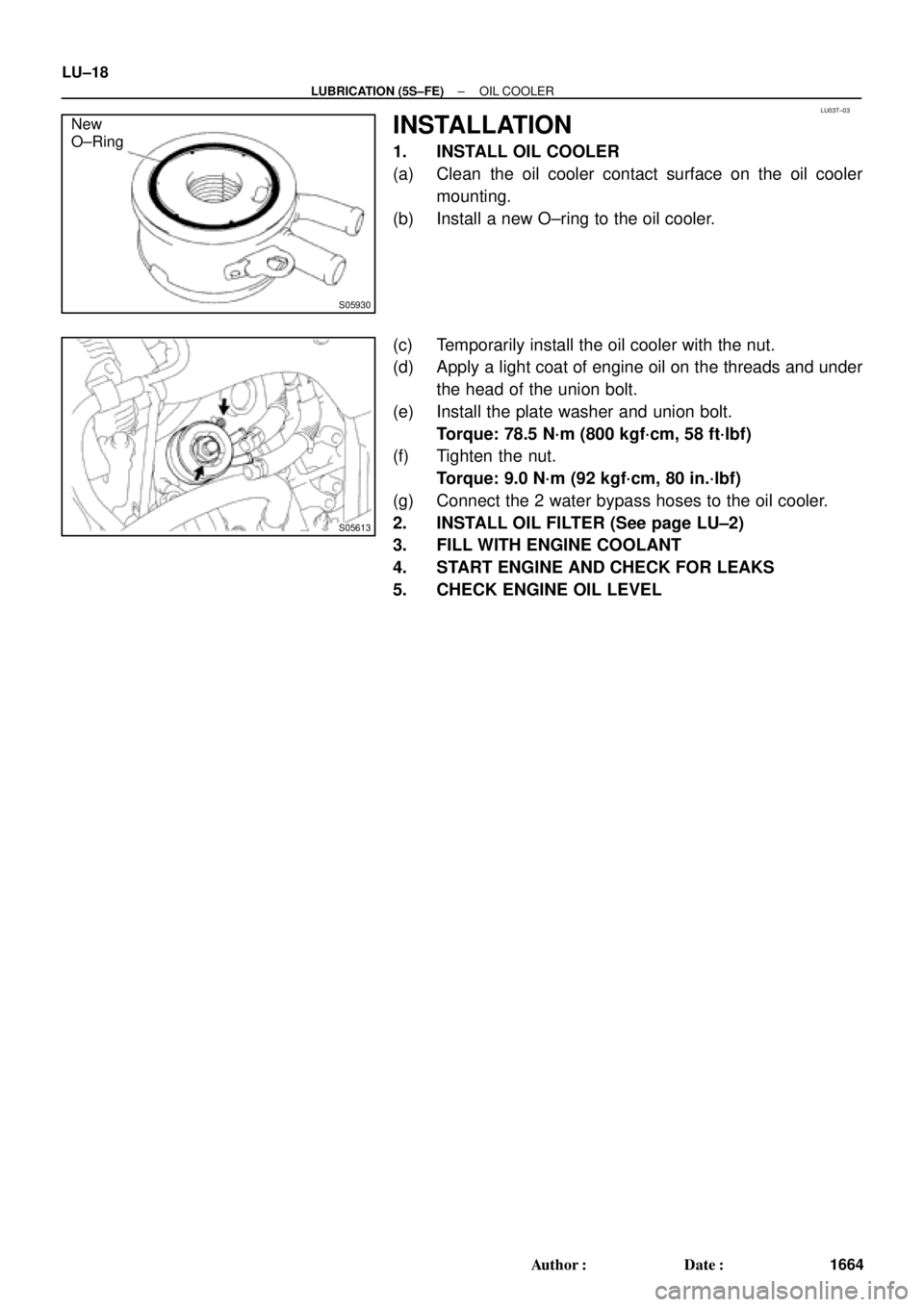
New
O±Ring
S05613
LU±18
± LUBRICATION (5S±FE)OIL COOLER
1664 Author�: Date�:
INSTALLATION
1. INSTALL OIL COOLER
(a) Clean the oil cooler contact surface on the oil cooler
mounting.
(b) Install a new O±ring to the oil cooler.
(c) Temporarily install the oil cooler with the nut.
(d) Apply a light coat of engine oil on the threads and under
the head of the union bolt.
(e) Install the plate washer and union bolt.
Torque: 78.5 N´m (800 kgf´cm, 58 ft´lbf)
(f) Tighten the nut.
Torque: 9.0 N´m (92 kgf´cm, 80 in.´lbf)
(g) Connect the 2 water bypass hoses to the oil cooler.
2. INSTALL OIL FILTER (See page LU±2)
3. FILL WITH ENGINE COOLANT
4. START ENGINE AND CHECK FOR LEAKS
5. CHECK ENGINE OIL LEVEL
Page 2908 of 4592
OIL AND FILTER
LU±3
1667 Author�: Date�:
REPLACEMENT
CAUTION:
�Prolonged and repeated contact with mineral oil wil")
LU026±03
P12486
P12580
SST
P12582
SST
Additional
3/4 Turn
± LUBRICATION (1MZ±FE)OIL AND FILTER
LU±3
1667 Author�: Date�:
REPLACEMENT
CAUTION:
�Prolonged and repeated contact with mineral oil will
result in the removal of natural fats from the skin,
leading to dryness, irritation and dermatitis. In addi-
tion, used engine oil contains potentially harmful
contaminants which may cause skin cancer.
�Exercise caution in order to minimize the length and
frequency of contact of your skin to used oil. Wear
protective clothing and gloves. Wash your skin thor-
oughly with soap and water, or use water±less hand
cleaner, to remove any used engine oil. Do not use
gasoline, thinners, or solvents.
�In order to preserve the environment, used oil and
used oil filter must be disposed of only at designated
disposal sites.
1. DRAIN ENGINE OIL
(a) Remove the oil filler cap.
(b) Remove the oil drain plug, and drain the oil into a contain-
er.
2. REPLACE OIL FILTER
(a) Using SST, remove the oil filter.
SST 09228±07501
(b) Check and clean the oil filter installation surface.
(c) Apply clean engine oil to the gasket of a new oil filter.
(d) Lightly screw the oil filter into place, and tighten it until the
gasket contacts the seat.
(e) Using SST, tighten it an additional 3/4 turn.
SST 09228±07501
Page 2925 of 4592

MA002±11
MA±2
± MAINTENANCEINSIDE VEHICLE
45 Author�: Date�:
INSIDE VEHICLE
GENERAL MAINTENANCE
These are maintenance and inspection items which are considered to be the owner's responsibility.
They can be done by the owner or they can have them done at a service shop.
These items include those which should be checked on a daily basis, those which, in most cases, do not
require (special) tools and those which are considered to be reasonable for the owner to do.
Items and procedures for general maintenance are as follows.
1. GENERAL NOTES
�Maintenance items may vary from country to country. Check the owner's manual supplement in which
the maintenance schedule is shown.
�Every service item in the periodic maintenance schedule must be performed.
�Periodic maintenance service must be performed according to whichever interval in the periodic main-
tenance schedule occurs first, the odometer reading (miles) or the time interval (months).
�Maintenance service after the last period should be performed at the same interval as before unless
otherwise noted.
�Failure to do even one item an cause the engine to run poorly and increase exhaust emissions.
2. LIGHTS
(a) Check that the headlights, stop lights, taillights, turn signal lights, and other lights are all working.
(b) Check the headlight aim.
3. WARNING LIGHTS AND BUZZERS
Check that all warning lights and buzzers function properly.
4. HORN
Check that it is working.
5. WINDSHIELD GLASS
Check for scratches, pits or abrasions.
6. WINDSHIELD WIPER AND WASHER
(a) Check operation of the wipers and washer.
(b) Check that the wipers do not streak.
7. WINDSHIELD DEFROSTER
Check that air comes out from the defroster outlet when operating the heater or air conditioner.
8. REAR VIEW MIRROR
Check that it is mounted securely.
9. SUN VISORS
Check that they move freely and are mounted securely.
10. STEERING WHEEL
Check that it has the specified freeplay. Be alert for changes in steering condition, such as hard steering,
excessive freeplay or strange noises.
11. SEATS
(a) Check that the seat adjusters operate smoothly.
(b) Check that all latches lock securely in any position.
(c) Check that the head restraints move up and down smoothly and that the locks hold securely in any
latch position.
(d) For fold±down seat backs, check that the latches lock securely.
12. SEAT BELTS
(a) Check that the seat belt system such as the buckles, retractors and anchors operate properly and
smoothly.
(b) Check that the belt webbing is not cut, frayed, worn or damaged.
Page 2929 of 4592
MA0055
MA00M±01
MA±6
± MAINTENANCEBRAKE
49 Author�: Date�:
BRAKE
INSPECTION
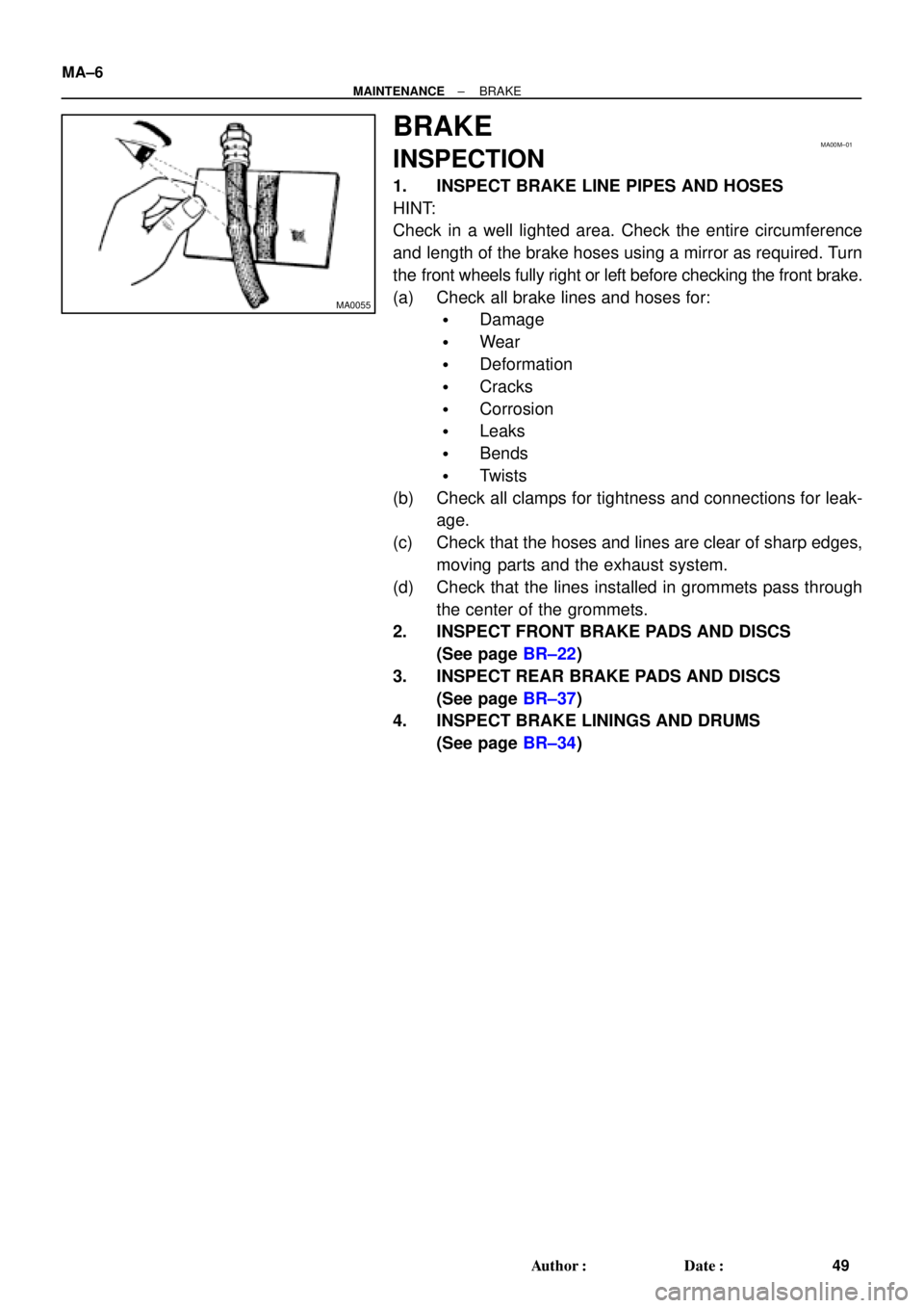
1. INSPECT BRAKE LINE PIPES AND HOSES
HINT:
Check in a well lighted area. Check the entire circumference
and length of the brake hoses using a mirror as required. Turn
the front wheels fully right or left before checking the front brake.
(a) Check all brake lines and hoses for:
�Damage
�Wear
�Deformation
�Cracks
�Corrosion
�Leaks
�Bends
�Twists
(b) Check all clamps for tightness and connections for leak-
age.
(c) Check that the hoses and lines are clear of sharp edges,
moving parts and the exhaust system.
(d) Check that the lines installed in grommets pass through
the center of the grommets.
2. INSPECT FRONT BRAKE PADS AND DISCS
(See page BR±22)
3. INSPECT REAR BRAKE PADS AND DISCS
(See page BR±37)
4. INSPECT BRAKE LININGS AND DRUMS
(See page BR±34)
Page 2936 of 4592

w/ Cruise Control :
Cruise Control Actuator
12 (120, 9)
Clutch Line Bracket
21 (210, 15)
12 (120, 9)
Clutch Release Cylinder
26 (270, 20)
RH Drive Shaft�
�32 (330, 2")
MX04Z±01
Q09981
Hood
14 (150, 10)
w/ Cruise Control :
Cruise Control Actuator
12 (120, 9)
Clutch Line Bracket
21 (210, 15)
12 (120, 9)
Clutch Release Cylinder
26 (270, 20)
RH Drive Shaft�
�32 (330, 24)
7.8 (80, 69 in.´lbf)
Flywheel Housing Under CoverRH Fender
Apron SealClutch Accumulator
Vehicle Speed Sensor
Connector
46 (470, 34)
Engine LH Mounting
Insulator with Bracket
Rear RH Suspension Member Brace
37 (380, 27)
Transaxle
64 (650, 47)
36 (370, 27)
10 (100, 7)
Steering Return Pipe
19 (195, 14)
32 (330, 24)
181 (1,850, 134)
Silver Bolt : 44 (450, 33)
Green Bolt : 66 (670, 48)
Suspension Member with
Lower Suspension Arm
Front RH Suspension
Member Brace
181 (1,850, 134)
Control
Cable
Clip13 (130, 9)
Clip
Washer
Starter
21 (210, 15)
39 (400, 29)
Air Cleaner
Case Assembly
with Air Hose
64 (650, 47)Ground Cable
x5Back±Up Light Switch Connector
Engine Wire
20 (200, 14)Hold±Down
Clamp
Battery
LH Drive Shaft
LH Fender Apron Seal RH Exhaust Manifold Stay
64 (650, 47)
181 (1,850, 134)PS Gear Assembly
No.1 Fuel Tube Protector
49 (500, 36)
294 (3,000, 217)
Lock Cap
Rear LH Suspension Member Brace
Stabilizer Bar Link
Hole
Plug
127 (1,300, 94)
39 (400, 29)
80 (820, 59)48 (490, 35)
Silver Bolt : 44 (450, 33)
Green Bolt : 66 (670, 48)
Front LH Suspension
Member Brace RH Fender
Liner
Engine Rear Side
Shutter Plate
56 (570, 41)
�
�
62 (630, 46) �
62 (630, 46) �
Front Exhaust Pipe
No.1 Exhaust Pipe
Support Bracket
33 (330, 24)
Exhaust Pipe Support Stay
33 (330, 24)LH Fender
Liner
66 (670, 48)
Snap Ring
�Snap Ring
�Cotter Pin
�Cotter Pin
�Gasket
�Gasket
�Gasket
Non±reusable part: Specified torque
N´m (kgf´cm, ft´lbf)
�
36 (370, 27)
± MANUAL TRANSAXLE (E153)MANUAL TRANSAXLE UNIT
MX±3
1804 Author�: Date�:
MANUAL TRANSAXLE UNIT
COMPONENTS
Page 2937 of 4592
MANUAL TRANSAXLE UNIT
1805 Author�: Date�:
REMOVAL
1. REMOVE HOOD
HINT:
At the time of installation, please refer to the following")
MX050±01
Q09982
Q09983
Q09984
Q09985
MX±4
± MANUAL TRANSAXLE (E153)MANUAL TRANSAXLE UNIT
1805 Author�: Date�:
REMOVAL
1. REMOVE HOOD
HINT:
At the time of installation, please refer to the following item.
Adjust the hood.
(See page BO±10)
2. REMOVE BATTERY AND AIR CLEANER CASE AS-
SEMBLY WITH AIR HOSE
3. w/ Cruise Control:
REMOVE CRUISE CONTROL ACTUATOR
(a) Disconnect the cruise control actuator connector.
(b) Remove the 3 bolts and cruise control actuator with the
bracket.
Torque: 13 N´m (130 kgf´cm, 9 ft´lbf)
4. REMOVE STARTER
(a) Disconnect the connector and wire from the starter.
(b) Remove the 2 bolts and starter.
Torque: 39 N´m (400 kgf´cm, 29 ft´lbf)
5. DISCONNECT CLUTCH RELEASE CYLINDER
(a) Remove the 2 bolts and disconnect the release cylinder.
Torque: 12 N´m (120 kgf´cm, 9 ft´lbf)
(b) Remove the 2 set bolts and nut of the clutch accumulator.
Torque:
Bolt: 21 N´m (210 kgf´cm, 15 ft´lbf)
Nut: 26 N´m (270 kgf´cm, 20 ft´lbf)
(c) Remove the set bolt of the clutch line bracket.
Torque: 12 N´m (120 kgf´cm, 9 ft´lbf)
6. DISCONNECT GROUND CABLE
Remove the set bolt of the ground cable from the transaxle.
7. DISCONNECT ENGINE WIRE FROM CLAMP
8. DISCONNECT VEHICLE SPEED SENSOR AND
BACK±UP LIGHT SWITCH CONNECTORS
9. DISCONNECT CONTROL CABLE
(a) Remove the 2 clips and washers.
(b) Remove the 2 clips from the cables.
Page 2940 of 4592
MANUAL TRANSAXLE UNIT
MX±7
1808 Author�: Date�:
21. REMOVE LH ENGINE MOUNTING INSULATOR WIT")
Q09994
Q09995
Q09996
CA
C
A
CB
AAB
C
Q09997
14 mm Head B14 mm Head B
14 mm Head A
± MANUAL TRANSAXLE (E153)MANUAL TRANSAXLE UNIT
MX±7
1808 Author�: Date�:
21. REMOVE LH ENGINE MOUNTING INSULATOR WITH
BRACKET
(a) Remove the 2 hole plugs, nuts and 3 bolts.
Torque:
Bolt: 64 N´m (650 kgf´cm, 47 ft´lbf)
Nut: 80 N´m (820 kgf´cm, 59 ft´lbf)
(b) Lift up the transaxle and remove the left engine mounting
insulator with the bracket.
22. REMOVE HOLE PLUG AND 4 ENGINE REAR SIDE
MOUNTING NUTS
Torque: 66 N´m (670 kgf´cm, 48 ft´lbf)
23. ATTACH ENGINE SLING DEVICE TO ENGINE HANG-
ER
(See page EM±69)
24. DISCONNECT STEERING RETURN PIPE FROM
FRONT SUSPENSION MEMBER
Remove the 2 bolts.
Torque: 10 N´m (100 kgf´cm, 7 ft´lbf)
25. REMOVE FRONT SUSPENSION MEMBER WITH LOW-
ER SUSPENSION ARM
(a) Remove the LH and RH fender liner set screws.
(b) Remove the 6 bolts, 4 nuts, front LH and RH suspension
member braces, rear LH and RH suspension member
braces and front suspension member with the lower sus-
pension arm.
Torque:
Bolt A: 181 N´m (1,850 kgf´cm, 134 ft´lbf)
Bolt B: 32 N´m (330 kgf´cm, 24 ft´lbf)
Nut C: 36 N´m (370 kgf´cm, 27 ft´lbf)
26. JACK UP TRANSAXLE SLIGHTLY
Using a transmission jack, support the transaxle.
27. REMOVE FLYWHEEL HOUSING UNDER COVER AND
TRANSAXLE LOWER SIDE MOUNTING BOLT
(a) Remove the 2 bolts and cover.
Torque: 7.8 N´m (80 kgf´cm, 69 in.´lbf)
(b) Remove the 3 bolts of the transaxle lower side.
Torque:
14 mm head A: 46 N´m (470 kgf´cm, 34 ft´lbf)
14 mm head B: 37 N´m (380 kgf´cm, 27 ft´lbf)