Page 3159 of 4592
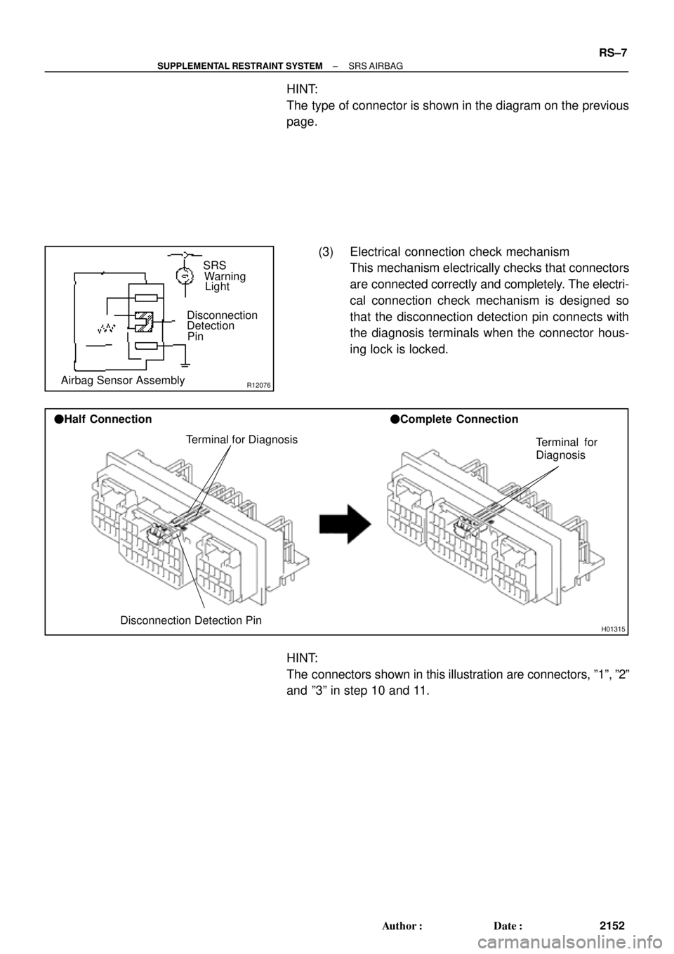
R12076Airbag Sensor AssemblyDisconnection
Detection
PinSRS
Warning
Light
H01315
Terminal for Diagnosis
Disconnection Detection Pin �Half Connection�Complete Connection
Terminal for
Diagnosis
± SUPPLEMENTAL RESTRAINT SYSTEMSRS AIRBAG
RS±7
2152 Author�: Date�:
HINT:
The type of connector is shown in the diagram on the previous
page.
(3) Electrical connection check mechanism
This mechanism electrically checks that connectors
are connected correctly and completely. The electri-
cal connection check mechanism is designed so
that the disconnection detection pin connects with
the diagnosis terminals when the connector hous-
ing lock is locked.
HINT:
The connectors shown in this illustration are connectors, º1º, º2º
and º3º in step 10 and 11.
Page 3161 of 4592

H01581
Outer
H01582
Lock of connector is released
Disconnection is completed
H01583
Outer
Outer
± SUPPLEMENTAL RESTRAINT SYSTEMSRS AIRBAG
RS±9
2154 Author�: Date�:
12. DISCONNECTION OF FRONT AIRBAG SENSOR AND
SIDE AIRBAG SENSOR CONNECTOR
(a) While holding both flank sides of the outer, slide the outer
to the direction shown by an arrow.
(b) Lock of the connectors is released, then disconnect the
connectors.
HINT:
Make sure to hold both flank sides of the outer. If holding the top
and bottom sides, it will obstruct disconnection.
13. CONNECTION OF FRONT AIRBAG SENSOR AND
SIDE AIRBAG SENSOR CONNECTOR
(a) Align the male connector (of the side of sensor) and fe-
male connector in the same direction as shown in the il-
lustration and fit in them without rubbing.
(b) As they are fitted in, the outer slides rearward. Press it un-
til the outer returns to its original position again.
If fitting stops half way, connectors will separate.
(c) Make sure to insert until they are locked. After fitting in,
pull them slightly to check that they are locked. (When
locked, make sure that the outer returns to its original
position and sound at the time of fitting in can be heard.)
HINT:
�Do not fit in while holding the outer.
�When fitting in, the outer slides. Do not touch it.
Page 3163 of 4592
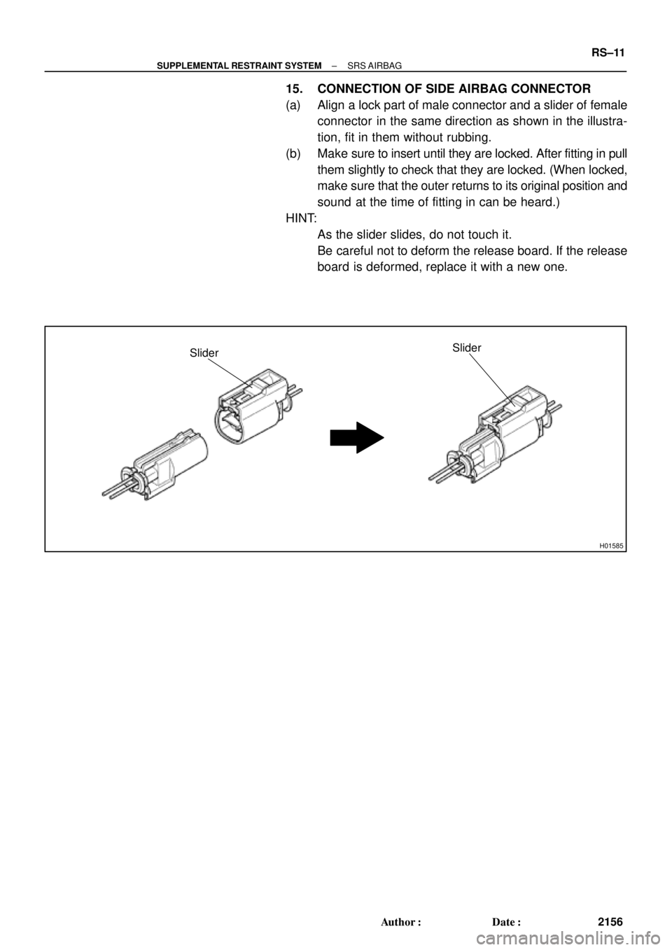
H01585
SliderSlider
± SUPPLEMENTAL RESTRAINT SYSTEMSRS AIRBAG
RS±11
2156 Author�: Date�:
15. CONNECTION OF SIDE AIRBAG CONNECTOR
(a) Align a lock part of male connector and a slider of female
connector in the same direction as shown in the illustra-
tion, fit in them without rubbing.
(b) Make sure to insert until they are locked. After fitting in pull
them slightly to check that they are locked. (When locked,
make sure that the outer returns to its original position and
sound at the time of fitting in can be heard.)
HINT:
�As the slider slides, do not touch it.
�Be careful not to deform the release board. If the release
board is deformed, replace it with a new one.
Page 3165 of 4592
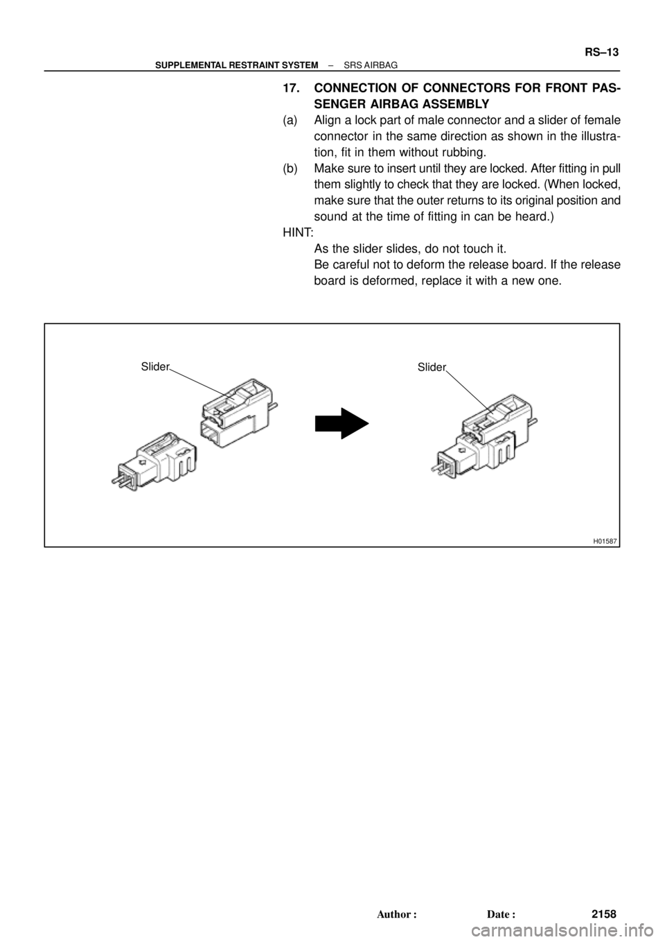
H01587
Slider
Slider
± SUPPLEMENTAL RESTRAINT SYSTEMSRS AIRBAG
RS±13
2158 Author�: Date�:
17. CONNECTION OF CONNECTORS FOR FRONT PAS-
SENGER AIRBAG ASSEMBLY
(a) Align a lock part of male connector and a slider of female
connector in the same direction as shown in the illustra-
tion, fit in them without rubbing.
(b) Make sure to insert until they are locked. After fitting in pull
them slightly to check that they are locked. (When locked,
make sure that the outer returns to its original position and
sound at the time of fitting in can be heard.)
HINT:
�As the slider slides, do not touch it.
�Be careful not to deform the release board. If the release
board is deformed, replace it with a new one.
Page 3171 of 4592

AB0158
SSTBattery
AB0152
SST
AB0158
SSTBattery
H01580
SST
W03515
± SUPPLEMENTAL RESTRAINT SYSTEMSTEERING WHEEL PAD AND SPIRAL CABLE
RS±19
2164 Author�: Date�:
1. AIRBAG DEPLOYMENT WHEN SCRAPPING VE-
HICLE
HINT:
Have a battery ready as the power source to deploy the airbag.
(a) Check functioning of the SST.
CAUTION:
When deploying the airbag, always use the specified SST:
SRS Airbag Deployment Tool.
SST 09082±00700
(1) Connect the SST to the battery.
Connect the red clip of the SST to the battery posi-
tive (+) terminal and the black clip to the battery neg-
ative (±) terminal.
HINT:
Do not connect the yellow connector which will be connected
with the supplemental restraint system.
(2) Check functioning of the SST.
Press the SST activation switch, and check that the
LED of the SST activation switch lights up.
CAUTION:
If the LED lights up when the activation switch is not being
pressed, SST malfunction is probable, so definitely do not
use the SST.
(b) Install the SST.
CAUTION:
Check that there is no looseness in the steering wheel and
steering wheel pad.
(1) Remove the steering column lower cover.
Remove the 3 screws and steering column lower
cover as shown in the illustration.
(2) Disconnect the airbag connector of the spiral cable.
Page 3172 of 4592
 or more
R06753
RS±20
± SUPPLEMENTAL RESTRAINT SYSTEMSTEERING WHEEL PAD AND SPIRAL CABLE
2165 Author�: Date�:
(3) Connect the SST connector to the airbag connector
of t")
W03508SST
R13455
10 m (33 ft) or more
R06753
RS±20
± SUPPLEMENTAL RESTRAINT SYSTEMSTEERING WHEEL PAD AND SPIRAL CABLE
2165 Author�: Date�:
(3) Connect the SST connector to the airbag connector
of the spiral cable.
SST 09082±00700
(4) Move the SST at least 10 m (33 ft) away from the
front of the vehicle.
(5) Close all the doors and windows of the vehicle.
NOTICE:
Take care not to damage the SST wire harness.
(6) Connect the SST red clip to the battery positive (+)
terminal and the black clip to the negative (±) termi-
nal.
(c) Deploy the airbag.
(1) Confirm that no one is inside the vehicle or within 10
m (33 ft) area around the vehicle.
(2) Press the SST activation switch and deploy the air-
bag.
HINT:
The airbag deploys simultaneously as the LED of the SST ac-
tivation switch lights up.
(d) Dispose of steering wheel pad (with airbag).
CAUTION:
�The steering wheel pad is very hot when the airbag is
deployed, so leave it alone for at least 30 minutes af-
ter deployment.
�Use gloves and safety glasses when handling a steer-
ing wheel pad with the deployed airbag.
�Always wash your hands with water after completing
the operation.
�Do not apply water, etc. to a steering wheel pad with
the deployed airbag.
(1) When scrapping a vehicle, deploy the airbag and
scrap the vehicle with the steering wheel pad still
installed.
(2) When moving a vehicle for scrapping which has a
steering wheel pad with deployed airbag, use
gloves and safety glasses.
Page 3176 of 4592
 or more
AB0166
RS±24
± SUPPLEMENTAL RESTRAINT SYSTEMSTEERING WHEEL PAD AND SPIRAL CABLE
2169 Author�: Date�:
CAUTION:
Do not use tires with disc wheels.
NOTICE:
The tires may be")
R13763
10 m (33 ft) or more
AB0166
RS±24
± SUPPLEMENTAL RESTRAINT SYSTEMSTEERING WHEEL PAD AND SPIRAL CABLE
2169 Author�: Date�:
CAUTION:
Do not use tires with disc wheels.
NOTICE:
The tires may be marked by the airbag deployment, so use
the redundant tires.
(g) Deploy the airbag.
(1) Connect the SST red clip to the battery positive (+)
terminal and the black clip to the battery negative
(±) terminal.
(2) Check that no one is within 10 m (33 ft) area around
the disc wheel which the steering wheel pad is tied
to.
(3) Press the SST activation switch and deploy the air-
bag.
HINT:
The airbag deploys simultaneously as the LED of the SST ac-
tivation switch lights up.
(h) Dispose of the steering wheel pad (with airbag).
CAUTION:
�The steering wheel pad is very hot when the airbag is
deployed, so leave it alone for at least 30 minutes af-
ter deployment.
�Use gloves and safety glasses when handling a steer-
ing wheel pad with deployed airbag.
�Always wash your hands with water after completing
the operation.
�Do not apply water, etc. to a steering wheel pad with
deployed airbag.
(1) Remove the steering wheel pad from the disc
wheel.
(2) Place the steering wheel pad in a vinyl bag, tie the
end tightly and dispose of it in the same way as oth-
er general parts disposal.
Page 3184 of 4592
 or more
H03286
RS±32
± SUPPLEMENTAL RESTRAINT SYSTEMFRONT PASSENGER AIRBAG ASSEMBLY
2177 Author�: Date�:
1. AIRBAG DEPLOYMENT WHEN SCRAPPING VE")
AB0158
SSTBattery
H03287
H08317SST
R13455
10 m (33 ft) or more
H03286
RS±32
± SUPPLEMENTAL RESTRAINT SYSTEMFRONT PASSENGER AIRBAG ASSEMBLY
2177 Author�: Date�:
1. AIRBAG DEPLOYMENT WHEN SCRAPPING VE-
HICLE
HINT:
Have a battery ready as the power source to deploy the airbag.
(a) Check functioning of the SST. (See page RS±18)
SST 09082±00700
(b) Disconnect the airbag connector.
(1) Remove the lower instrument cover inside the No.2
under cover.
NOTICE:
When handling the airbag connector, take care not to dam-
age the airbag wire harness.
(2) Pull up the connector.
(3) Disconnect the airbag connector.
(c) Install the SST.
(1) Connect the connector of 2 SST to the front passen-
ger airbag assembly connector.
SST 09082±00700, 09082±00760
NOTICE:
To avoid damaging the SST connector and wire harness,
do not lock the secondary lock of the twin lock.
(2) Move the SST to at least 10 m (33 ft) away from the
front of the vehicle.
(3) Close all the doors and windows of the vehicle.
NOTICE:
Take care not to damage the SST wire harness.
(4) Connect the SST red clip to the battery positive (+)
terminal and the black clip to the negative (±) termi-
nal.
(d) Deploy the airbag.
(1) Check that no one is inside the vehicle or within 10
m (33 ft) area around the vehicle.
(2) Press the SST activation switch and deploy the air-
bag.
HINT:
The airbag deploys simultaneously as the LED of the SST ac-
tivation switch lights up.