Page 3291 of 4592
± SERVICE SPECIFICATIONSMANUAL TRANSAXLE (S51)
SS±53
216 Author�: Date�:
Engine mount bracket x Transaxle5253038
Reverse shift arm bracket1818513
No.3 shift fork x Shift fork shaft1818513
Lock ball assembly2930022
Filler and Drain plugs4950036
Back±up light switch4445033
Differential side bearing retainer1818513
Release bearing retainer7.47565 in.´lbf
Straight screw plug131309
Vehicle speed sensor driven gear5.45548 in.´lbf
Clutch release fork support3940029
Page 3324 of 4592
SFI SYSTEM
1435 Author�: Date�:
(b) When installing the battery, be especially careful not to in-
correctly connect the positive")
FI2553
SST
S04600
Fuel
Pump
Connector
S05326
Plug SF±2
± SFI (5S±FE)SFI SYSTEM
1435 Author�: Date�:
(b) When installing the battery, be especially careful not to in-
correctly connect the positive (+) and negative (±) cables.
(c) Do not permit parts to receive a severe impact during re-
moval or installation. Handle all SFI parts carefully, espe-
cially the ECM.
(d) Be careful during troubleshooting as there are numerous
transistor circuit, and even slight terminal contact can
cause further troubles.
(e) Do not open the ECM cover.
(f) When inspecting during rainy weather, take care to pre-
vent entry of water. Also, when washing the engine
compartment, prevent water from getting on the SFI parts
and wiring connectors.
(g) Parts should be replaced as an assembly.
(h) Care should be taken when pulling out and inserting wir-
ing connectors.
(1) Release the lock and pull out the connector, pulling
on the connectors.
(2) Fully insert the connector and check that it is locked.
(i) Use SST for inspection or test of the injector or its wiring
connector.
SST 09842±30070
8. FUEL SYSTEM
(a) When disconnecting the high fuel pressure line, a large
amount of gasoline will spill out, so observe these proce-
dures:
(1) Disconnect the fuel pump connector.
(2) Start the engine. After the engine has stopped on
its own, turn the ignition switch OFF.
(3) Put a container under the connection.
(4) Slowly loosen the connection.
(5) Disconnect the connection.
(6) Plug the connection with a rubber plug.
(7) Reconnect the fuel pump connector.
Page 3325 of 4592
SFI SYSTEM
SF±3
1436 Author�: Date�:
(b) When connecting the union bolt on t")
S05523
New Gasket
FI1654
SST
30 cm Fulcrum Length
FI0420
Injector
GrommetO±Ring
Delivery PipeCORRECT
WRONG
± SFI (5S±FE)SFI SYSTEM
SF±3
1436 Author�: Date�:
(b) When connecting the union bolt on the high pressure pipe
union, observe these procedures:
(1) Always use 2 new gaskets.
(2) Tighten the union bolt by hand.
(3) Tighten the union bolt to the specified torque.
Torque: 29 N´m (300 kgf´cm, 21 ft´lbf)
(c) When connecting the flare nut on the high pressure pipe
union, observe these procedures:
(1) Apply a light coat of engine oil to the flare nut, and
tighten the flare nut by hand.
(2) Using SST, tighten the flare nut to specified torque.
SST 09631±22020
NOTICE:
Do not rotate the fuel pipe, when tightening the flare nut.
Torque: 28 N´m (285 kgf´cm, 21 ft´lbf) for using SST
HINT:
Use a torque wrench with a fulcrum length of 30 cm (11.81 in.).
(d) Observe these precautions when removing and installing
the injectors.
(1) Never reuse the O±ring.
(2) When placing a new O±ring on the injector, take
care not to damage it in any way.
(3) Coat a new O±ring with spindle oil or gasoline be-
fore installing±never use engine, gear or brake oil.
Page 3334 of 4592
(3)
(2) Type B SF±12
± SFI (5S±FE)FUEL PUMP
1445 Author�: Date�:
DISASSEMBLY
1. DISCONNECT FUEL PUMP CONNECTOR")
SF0DA±02
S06028
Type B
S04603Pull Type A
S06033
PushA Type B
S06050
Type B
S06030
(1)(3)
(2) Type B SF±12
± SFI (5S±FE)FUEL PUMP
1445 Author�: Date�:
DISASSEMBLY
1. DISCONNECT FUEL PUMP CONNECTOR
2. Type B:
DISCONNECT GROUND PLATE
3. Type B:
DISCONNECT FUEL SENDER GAUGE CONNECTOR
4. Type A:
REMOVE FUEL PUMP FROM FUEL PUMP BRACKET
(a) Pull off the lower side of the fuel pump from the pump
bracket.
(b) Disconnect the fuel hose from the fuel pump, and remove
the fuel pump.
(c) Remove the rubber cushion from the fuel pump.
5. Type B:
REMOVE FUEL SENDER GAUGE.
Push down the portion of A with a finger, and push up the send-
er gauge.
NOTICE:
Be careful that the arm of the sender gauge should not
bent.
6. Type B:
REMOVE FUEL FILTER
(a) Remove the screw, and pull out the fuel filter.
(b) Remove the O±ring from the fuel filter.
HINT:
At the time of installation, please refer to the following items. Ap-
ply a light coat of gasoline to a new O±ring, and install it to the
fuel filter.
Torque: 2.0 N´m (20 kgf´cm, 17 in.´lbf)
7. Type B:
REMOVE FUEL PUMP FLANGE
Using a screwdriver, remove the snap fit portion in the order of
1, 2 and 3 as shown in the illustration.
HINT:
At the time of installation, please refer to the following items. Ap-
ply a light coat of gasoline to a new O±ring of the fuel pump.
Page 3340 of 4592
SF0DE±03
S04591
S04590
SF±18
± SFI (5S±FE)FUEL PRESSURE REGULATOR
1451 Author�: Date�:
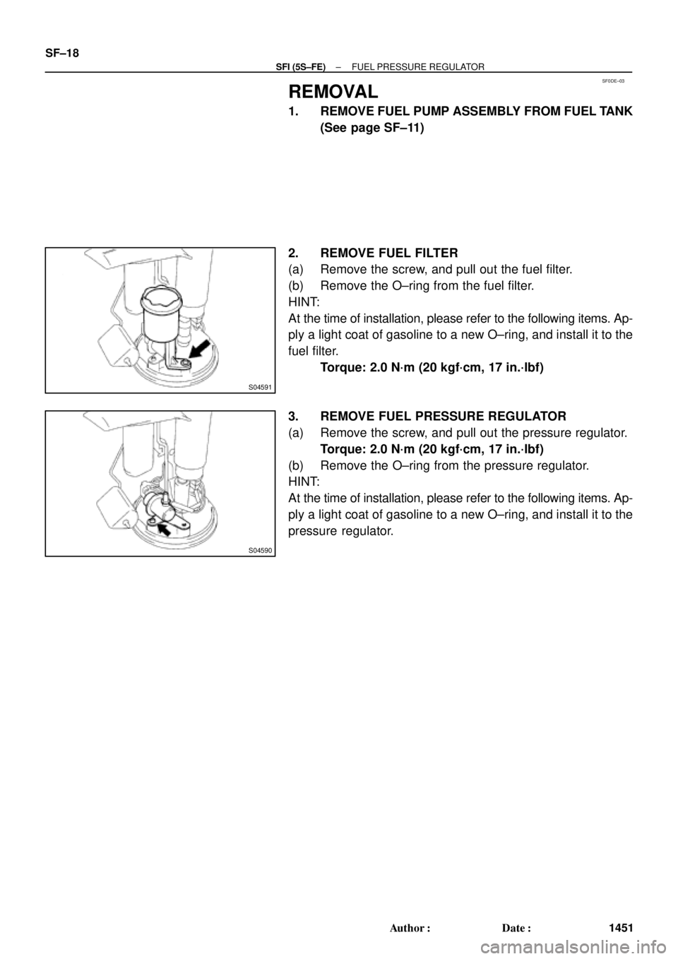
REMOVAL
1. REMOVE FUEL PUMP ASSEMBLY FROM FUEL TANK
(See page SF±11)
2. REMOVE FUEL FILTER
(a) Remove the screw, and pull out the fuel filter.
(b) Remove the O±ring from the fuel filter.
HINT:
At the time of installation, please refer to the following items. Ap-
ply a light coat of gasoline to a new O±ring, and install it to the
fuel filter.
Torque: 2.0 N´m (20 kgf´cm, 17 in.´lbf)
3. REMOVE FUEL PRESSURE REGULATOR
(a) Remove the screw, and pull out the pressure regulator.
Torque: 2.0 N´m (20 kgf´cm, 17 in.´lbf)
(b) Remove the O±ring from the pressure regulator.
HINT:
At the time of installation, please refer to the following items. Ap-
ply a light coat of gasoline to a new O±ring, and install it to the
pressure regulator.
Page 3347 of 4592
SF0Z8±01
Z09141
California
Except CaliforniaNew O±RingNew Insulator
New GrommetNew O±Ring
New GrommetNew
O±Ring
S05980
Spacer New InsulatorSpacer
S05978
Upward
Turn
Connector
Push
± SFI (5S±FE)INJECTOR
SF±25
1458 Author�: Date�:
INSTALLATION
1. INSTALL INJECTORS AND DELIVERY PIPE
(a) California:
Install new insulator and grommet to each injector.
(b) Except California:
Install a new grommet to each injector.
(c) California:
Apply a light coat of gasoline onto 2 new O±rings, and
install them to each injector.
(d) Except California:
Apply a light coat of gasoline onto a new O±ring, and
install it to each injector.
(e) Install the 2 spacers and 4 new insulators to the cylinder
head.
(f) While turning the injector left and right, install it to the de-
livery pipe. Install the 4 injectors.
(g) Position the injector connector upward.
Page 3390 of 4592
SFI SYSTEM
1501 Author�: Date�:
(b) When installing the battery, be especially careful not to in-
correctly connect the positive")
FI2553
SST
S04600
Fuel
Pump
Connector
S05039
Plug
SF±2
± SFI (1MZ±FE)SFI SYSTEM
1501 Author�: Date�:
(b) When installing the battery, be especially careful not to in-
correctly connect the positive (+) and negative (±) cables.
(c) Do not permit parts to receive a severe impact during re-
moval or installation. Handle all SFI parts carefully, espe-
cially the ECM.
(d) Be careful during troubleshooting as there are numerous
transistor circuit, and even slight terminal contact can
cause further troubles.
(e) Do not open the ECM cover.
(f) When inspecting during rainy weather, take care to pre-
vent entry of water. Also, when washing the engine
compartment, prevent water from getting on the SFI parts
and wiring connectors.
(g) Parts should be replaced as an assembly.
(h) Care should be taken when pulling out and inserting wir-
ing connectors.
(1) Release the lock and pull out the connector, pulling
on the connectors.
(2) Fully insert the connector and check that it is locked.
(i) Use SST for inspection or test of the injector or its wiring
connector.
SST 09842±30070
8. FUEL SYSTEM
(a) When disconnecting the high fuel pressure line, a large
amount of gasoline will spill out, so observe these proce-
dures:
(1) Disconnect the fuel pump connector.
(2) Start the engine. After the engine has stopped on
its own, turn the ignition switch to LOCK.
(3) Put a container under the connection.
(4) Slowly loosen the connection.
(5) Disconnect the connection.
(6) Plug the connection with a rubber plug.
Page 3391 of 4592
SFI SYSTEM
SF±3
1502 Author�: Date�:
(b) When connecting the union bolt on th")
S05054
New Gasket
FI1654
Fulcrum Length
30 cm
SST
FI6372 FI6372
New O±Ring
Grommet
InjectorCORRECT
WRONG
± SFI (1MZ±FE)SFI SYSTEM
SF±3
1502 Author�: Date�:
(b) When connecting the union bolt on the high pressure pipe
union, observe these procedures:
(1) Always use 2 new gaskets.
(2) Tighten the union bolt by hand.
(3) Tighten the union bolt to the specified torque.
Torque: 32.5 N´m (330 kgf´cm, 24 ft´lbf)
(c) When connecting the flare nut on the high pressure pipe
union, observe these procedures:
(1) Apply a light coat of engine oil to the flare nut, and
tighten the flare nut by hand.
(2) Using SST, tighten the flare nut to specified torque.
SST 09631±22020
NOTICE:
Do not rotate the fuel pipe, when tightening the flare nut.
Torque: 28 N´m (285 kgf´cm, 21 ft´lbf) for using SST
HINT:
Use a torque wrench with a fulcrum length of 30 cm (11.81 in.).
(d) Observe these precautions when removing and installing
the injectors.
(1) Never reuse the O±ring.
(2) When placing a new O±ring on the injector, take
care not to damage it in any way.
(3) Coat a new O±ring with spindle oil or gasoline be-
fore installing±never use engine, gear or brake oil.

I")