Page 3851 of 4592

1999 PAINT AND REFINISH FORMULA CODES ± PA002±99 March 12, 1999
Page 3 of 5
COLOR
CODECOLOR NAMEBASFDUPONTICI
AUTOCOLORPPGSHERWIN
WILLIAMSSIKKENSSPIES±
HECKERSTANDOX
4M7Oyster PearlTOY4M7K99685MK6B2757948841TOY4M7106554M7
4M9Cashmere Beige
MetallicTOY4M9N99246ED6B490349702TOY4M9202614M9
4N5Vintage Rose MetallicTOY4N5F2716HYV5B533954862TOY4N5158174N5
4N7Sable PearlTOY4N7F3748LJC3B544856740TOY4N7222364N7
4P1Antique Bronze MetallicTOY4P1F4465KWC1B542256659TOY4P1816424P1
4P3Desert Bronze MetallicLEX4P3F7145LVT4B2876457228LEX4P3223174P3
4P5Autumn Blaze MetallicTOY4P5F5583PEC1B552658340TOY4P5346234P5
4P6Autumn Red MicaTOY4P6F5139NPD8B556557929TOY4P6345884P6
578Golden Sand MetallicTOY578F3749LNX6B545756741TOY57822189578
6M1Dark Emerald PearlTOY6M1W9542PM72B459546589TOY6M1997466M1
6M3Silver Spruce MetallicTOY6M3W9514D381B447445931TOY6M3996796M3
6N7Sierra Green MetallicTOY6N7F10367P07B504751163TOY6N7613916N7
6P2Classic Green PearlTOY6P2F1850BAA7B517352889TOY6P2619536P2
6P3Deep Jewel
Grean PearlTOY6P3F1805ARD3B516652887TOY6P3619286P3
6P4Surfside Green MicaTOY6P4F2690GNL1B528954293TOY6P4640186P4
6Q7Imperial Jade MicaTOY6Q7F3750KWC2B542356660TOY6Q7680966Q7
6R1Woodland PearlTOY6R1F7147LVT6B556657230TOY6R1653216R1
6R3Fairway Green PearlTOY6R3F5140NPD9B556757930TOY6R3657066R3
760Mystic Teal MicaTOY760F3533LCP2B544556258TOY76065225760
762Aqua Blue MetallicTOY762F8543PEJ8B559558693TOY76256812762
8L3Blue Velvet PearlTOY8L3F2239FRC7B532854032TOY8L3546768L3
8L4Atlantis Blue MicaTOY8L4F1898BGT9B1970552994TOY8L4544838L4
8L5Royal Sapphire BlueTOY8L5F2728HDJ4B532954485TOY8L5550688L5
8L7Stellar Blue PearlTOY8L7F2059ETB9B520653072TOY8L7545628L7
8L9Denim Blue MicaTOY8L9F2722JCD1B544354872TOY8L9553258L9
8M5Mista Blue MicaTOY8M5F3562KBA1B543456261TOY8M5558258M5
8M8Twilight Blue PearlTOY8M8F7274LXY2B19092557452TOY8M8565428M8
8N1Horizon Blue MetallicTOY8N1F5223PEC2B552758341TOY8N1568138N1
930Blue Dusk PearlTOY930F2723HRE6B533054758TOY93040713930
931Frosted Iris MetallicTOY931F2724HRE7B533154759TOY93140714931
938Mystic Purple MicaTOY938F3532KWB7B542056656TOY93840930938
Paint Codes &
Color Names
(Continued)
Page 3883 of 4592

Toyota Supports ASE CertificationPage 1 of 3
PG006±03
Title:
WARRANTY PARTS
MARKING PROCEDURE
Models:
All Models
Technical Service
BULLETIN
September 26, 2003
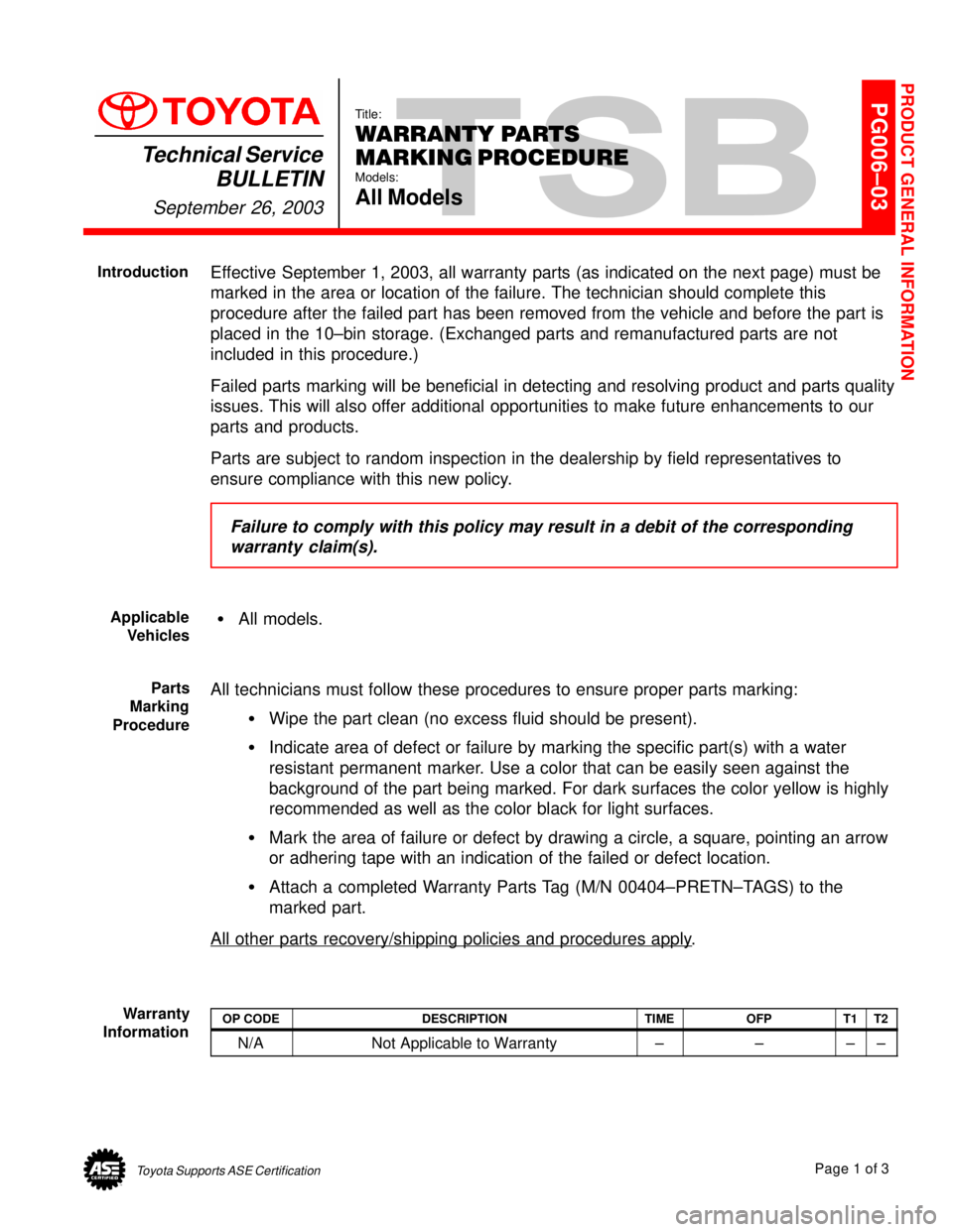
Effective September 1, 2003, all warranty parts (as indicated on the next page) must be
marked in the area or location of the failure. The technician should complete this
procedure after the failed part has been removed from the vehicle and before the part is
placed in the 10±bin storage. (Exchanged parts and remanufactured parts are not
included in this procedure.)
Failed parts marking will be beneficial in detecting and resolving product and parts quality
issues. This will also offer additional opportunities to make future enhancements to our
parts and products.
Parts are subject to random inspection in the dealership by field representatives to
ensure compliance with this new policy.
Failure to comply with this policy may result in a debit of the corresponding
warranty claim(s).
�All models.
All technicians must follow these procedures to ensure proper parts marking:
�Wipe the part clean (no excess fluid should be present).
�Indicate area of defect or failure by marking the specific part(s) with a water
resistant permanent marker. Use a color that can be easily seen against the
background of the part being marked. For dark surfaces the color yellow is highly
recommended as well as the color black for light surfaces.
�Mark the area of failure or defect by drawing a circle, a square, pointing an arrow
or adhering tape with an indication of the failed or defect location.
�Attach a completed Warranty Parts Tag (M/N 00404±PRETN±TAGS) to the
marked part.
All other parts recovery/shipping policies and procedures apply
.
OP CODEDESCRIPTIONTIMEOFPT1T2
N/ANot Applicable to Warranty±±±±
PRODUCT GENERAL INFORMATION
Introduction
Applicable
Vehicles
Parts
Marking
Procedure
Warranty
Information
Page 3884 of 4592

WARRANTY PARTS MARKING PROCEDURE ± PG006-03September 26, 2003
Page 2 of 3
Dealers are requested to mark the location of the failure of all warranty parts that are
listed below.
This list is not inclusive. There may be other components that can be
marked in the area of failure. All other parts that can be marked should be marked.
assist grip assy headlamps
audio (blemish) headliner
back door garnish hoses
bumper covers instrument panel safety pad sub±assy
cargo cover (retractable) Interior light assemblies and covers
carpet knobs, levers, handles
clutch disc l/pulley pump assy
clutch flywheel mirrors (side and rearview)
combination meter glass navigation or VES screens
console and components pillar garnish
cowl assy rack and pinion/power steering gear assy
cowl side trim sub±assy radiator
cupholders room partition board
cylinder head cover sub±assy rotors (mark where min. runout is exceeded or warped)
dash panel insulator assy seat covers/cushions
dashboard and trim seat tracks
disc wheel soft trim
display panels spare tire cover
door handle assy steering column cover
door moulding steering wheel
door trim panel & molding tail lamps and covers
emblems transmission oil pan
engine oil pan visor
exhaust manifold washer jar
floor and cargo mats wheel cap
gear shift knob wheels
grills
Parts
Marking
Requirement
Parts
Marking
List
Page 3906 of 4592
SCANTOOL IMMOBILIZER KEY CODE UTILITY ± SS001±99 April 9, 1999
Page 5 of 9
3. From the ªKEY SELECTIONº menu
(Screen C), select the Transponder
Key type to be registered and press
the (ENTER) key.
NOTE:
Do not register a SUB KEY as a
MASTER KEY. The SUB KEY is
typically left with an attendant when
the vehicle is parked. A Registered
Master Key allows the user to
add/erase transponder keys.
4. From ªKEY SELECTIONº (Screen D),
confirm the type of Transponder Key
to be registered and press the
(ENTER) key.
5. After pressing the (YES) key, remove
the Registered Master Key from the
Ignition Cylinder within 20 seconds.
After removing the key, press the
(ENTER) key.
6. Insert the New Transponder Key into
the Ignition Cylinder within 10
seconds and press the (ENTER) key.
HINT:
Look at the Security Indicator Light. It
will begin to flash as the New
Transponder Key is inserted.
Page 3909 of 4592

SCANTOOL IMMOBILIZER KEY CODE UTILITY ± SS001±99 April 9, 1999
Page 8 of 9
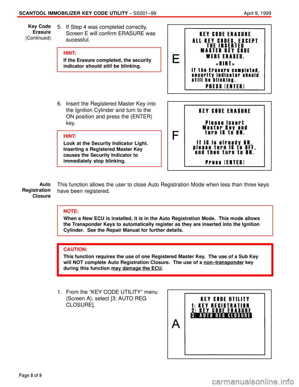
5. If Step 4 was completed correctly,
Screen E will confirm ERASURE was
sucessful.
HINT:
If the Erasure completed, the security
indicator should still be blinking.
6. Insert the Registered Master Key into
the Ignition Cylinder and turn to the
ON position and press the (ENTER)
key.
HINT:
Look at the Security Indicator Light.
Inserting a Registered Master Key
causes the Security Indicator to
immediately stop blinking.
This function allows the user to close Auto Registration Mode when less than three keys
have been registered.
NOTE:
When a New ECU is installed, it is in the Auto Registration Mode. This mode allows
the Transponder Keys to automatically register as they are inserted into the Ignition
Cylinder. See the Repair Manual for further details.
CAUTION:
This function requires the use of one Registered Master Key. The use of a Sub Key
will NOT complete Auto Registration Closure. The use of a non±transponder
key
during this function may damage the ECU
.
1. From the ªKEY CODE UTILITYª menu
(Screen A), select [3: AUTO REG
CLOSURE].
Key Code
Erasure
(Continued)
Auto
Registration
Closure
Page 3929 of 4592
TOYOTA MOTOR SALES U.S.A., INC.
Beginning in 1996, Toyota will be standardizing the size of many of its oil filters to the three inch
industry standard. This new filter size is slightly larger than the existing 75mm diameter filter
presently used on many Toyota models. This larger filter will require a three inch oil filter wrench
for easy removal.
Three inch oil filter wrenches are readily available from parts stores and tool dealers, however, for
your convenience, OTC will make this new filter wrench available under P/N 00002±17001. Dealer
cost is $5.75. To order, please call OTC at 1±800±933±8335.
NEW OIL FILTER WRENCHPage 1 of 1
NOVEMBER 10, 1995
SPECIAL SERVICE
TOOLS
SS95±004
ALL MODELS
Page 3933 of 4592

Toyota Supports ASE CertificationPage 1 of 1
ST002±98Title:
STEERING GEAR REMOVAL/
REPLACEMENT
Models:
All Models equipped with SRS Airbag
Technical Service
BULLETIN
May 22, 1998
The following information is provided to supplement the Repair Manual procedure
for
removing/installing the steering gearbox or rack and pinion on vehicles equipped with a
driver 's side Supplemental Restraint System (SRS) Airbag.
CAUTION:
When the intermediate shaft is disconnected and the steering wheel is turned freely,
the SRS spiral cable may be broken.
Therefore, as a precaution, make sure to pass
the driver's seat belt through the steering wheel to prevent it from turning freely, as
shown below.
After working on SRS/Steering components, always check the operation of the SRS
Warning Light. Refer to the appropriate repair manual if any diagnostic trouble codes
are recorded.
Tercel, Paseo, Corolla, MR2, Celica, Camry, Avalon, Supra, Previa, Sienna, RAV4,
4Runner, Tacoma, T±100 & Land Cruiser equipped with a driver's side SRS Airbag.
1. Position the front wheels facing
straight ahead.
2. Using the driver's seat belt, set the
steering wheel so that it does not turn
(see Fig. 1).
3. Paint match marks on the
intermediate shaft and control valve
shaft (see Fig. 2).
4. Remove the intermediate shaft
retaining bolt and disconnect the
intermediate shaft (see Fig. 2).
OP CODEDESCRIPTIONTIMEOPNT1T2
N/ANot Applicable to Warranty ±±±±
STEERING
Introduction
Affected
Vehicles
Fig. 1
Repair
Procedure
Match Marks
Fig.2
Warranty
Information
Page 3941 of 4592

Toyota Supports ASE CertificationPage 1 of 1
SU002±00Title:
REAR ABS SPEED SENSOR REMOVAL
Models:
'97 ± '00 Camry & Avalon, '99 ± '00 Solara
Technical Service
BULLETIN
May 5, 2000
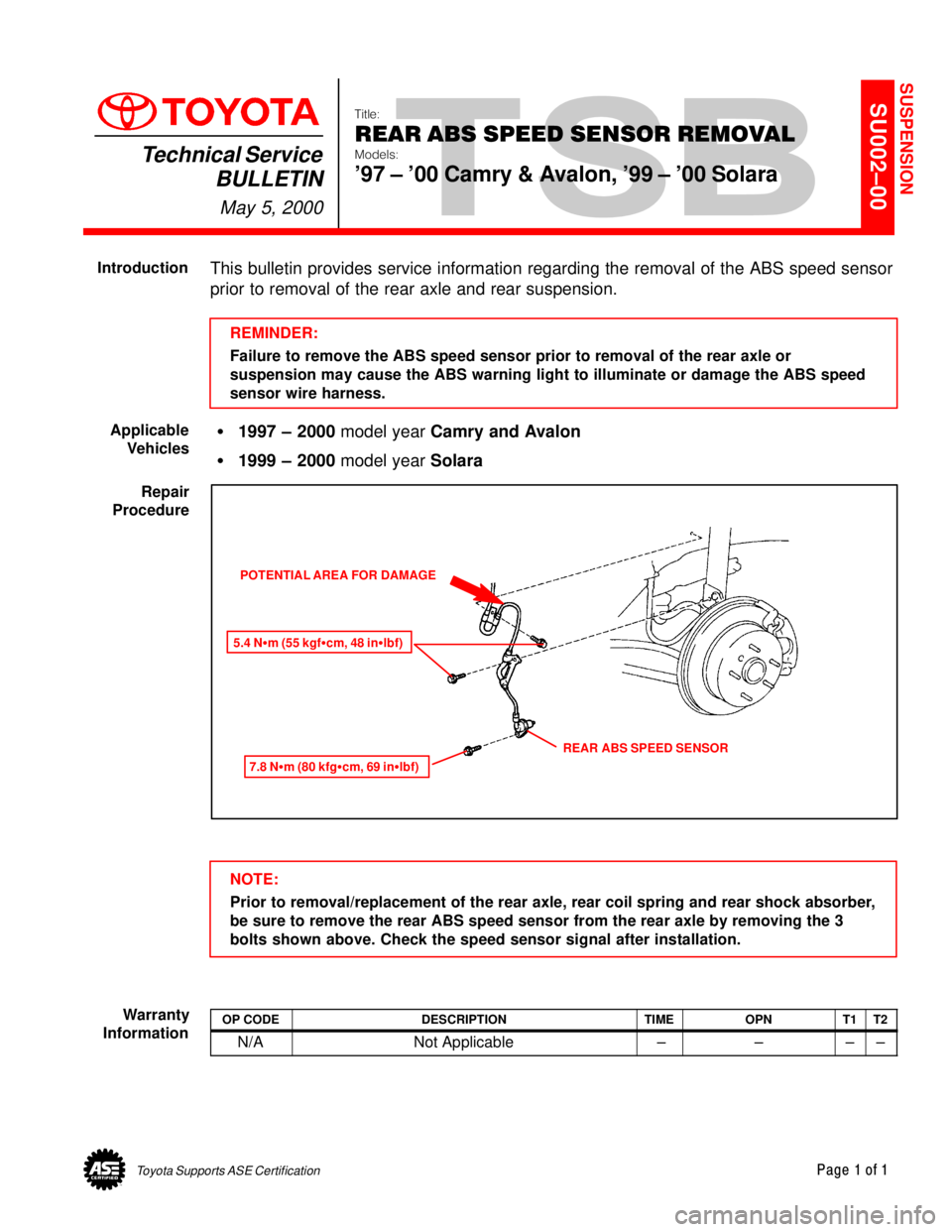
This bulletin provides service information regarding the removal of the ABS speed sensor
prior to removal of the rear axle and rear suspension.
REMINDER:
Failure to remove the ABS speed sensor prior to removal of the rear axle or
suspension may cause the ABS warning light to illuminate or damage the ABS speed
sensor wire harness.
�1997 ± 2000 model year Camry and Avalon
�1999 ± 2000 model year Solara
POTENTIAL AREA FOR DAMAGE
5.4 N�m (55 kgf�cm, 48 in�lbf)
7.8 N�m (80 kfg�cm, 69 in�lbf)
REAR ABS SPEED SENSOR
NOTE:
Prior to removal/replacement of the rear axle, rear coil spring and rear shock absorber,
be sure to remove the rear ABS speed sensor from the rear axle by removing the 3
bolts shown above. Check the speed sensor signal after installation.
OP CODEDESCRIPTIONTIMEOPNT1T2
N/ANot Applicable ±±±±
SUSPENSION
Introduction
Applicable
Vehicles
Repair
Procedure
Warranty
Information