Page 3667 of 4592
TOYOTA VIP RS3000 PROGRAMMING ± ALL MODELS ± AX005±99 April 9, 1999
Page 2 of 4
For location of the RS3000 ECU, refer to ECU Mounting Locations, Page 4.
I. To program (add) a REMOTE CONTROL to the system:
1. Insert the key into ignition switch,
and turn it to ªONº.
2. Press and hold the ECU's
PROGRAMMING SWITCH for 3
seconds.
The STATUS MONITOR LED
turns on for 5 seconds.
NOTE:
YOU MUST PERFORM THE NEXT
STEP WITHIN 5 SECONDS.
3. Press and release a REMOTE
CONTROL's top or bottom
button.*
The STATUS MONITOR LED
turns off.
The Piezo ªchirperº chirps once.
The exterior lights flash once.
4. Turn off the ignition. The ECU will
now operate with the REMOTE
CONTROL just programmed.
* Either button on your REMOTE CONTROL can be programmed to operate the system. The bottom
button can be programmed to operate a second vehicle with the Toyota VIP.
Programming
Procedure
Press and Hold
for 3 Seconds
Lights Up
Press Once
Page 3668 of 4592
TOYOTA VIP RS3000 PROGRAMMING ± ALL MODELS ± AX005±99 April 9, 1999
Page 3 of 4
II. To erase all REMOTE CONTROL codes from the system:
1. Insert key into the ignition switch,
and turn it to ªONº.
2. Press and hold the ECU's
PROGRAMMING SWITCH for 3
seconds.
The STATUS MONITOR LED
turns on for 5 seconds.
NOTE:
YOU MUST PERFORM THE NEXT
STEP WITHIN 5 SECONDS.
3. Press and hold the ECU's
PROGRAMMING SWITCH for
over 2 seconds again.
The STATUS MONITOR LED
turns off, then flashes 3 times.
The Piezo ªchirperº chirps three
times and the exterior lights flash
3 times.
4. Turn off the ignition. The ECU has cleared all REMOTE CONTROL codes; until
another REMOTE CONTROL is programmed, the system will not work with any
REMOTE CONTROL.
Programming
Procedure
(Continued)
Press and Hold
for 3 Seconds
Lights Up
Press and Hold Again, for 2
Seconds
Page 3671 of 4592

RS30000 TVIP AUTOMATIC DOOR LOCK FEATURE PROGRAMMING ± AX005±00 April 14, 2000
Page 2 of 2
AUTOMATIC (IGNITION±CONTROLLED) DOOR LOCKING/UNLOCKING FUNCTION
The factory setting for the Automatic Door Locking/Unlocking Function is ªONº.
To change this feature's operation, follow the steps below:
1. Sit in the driver's seat with driver's door open.
2. Insert the key into the ignition switch, and turn it to ªONº position (not ªACCº)
5 times (ON > LOCK > ON > LOCK > ON > LOCK > ON > LOCK > ON) within a
10 second period.
System Response: The STATUS MONITOR's LED turns on, and the PIEZO
BUZZER sounds once.
NOTE:
You must perform the next steps within 30 seconds.
3. Select the customer's preferred operating mode.
ModeProgramming StepProgramming Completion
AUTOMATIC DOOR
LOCKING/UNLOCKING ªONºClose the driver's door.
Turn the ignition switch to the
ªLOCKº position.
System Response:
The PIEZO BUZZER sounds
once, and the exterior lights
flash once.
AUTOMATIC DOOR
LOCKING/UNLOCKING ªOFFºClose the driver's door,
then open and close it
one more time.
Turn the ignition switch to the
ªLOCKº position.
System Response:
The PIEZO BUZZER sounds
twice, and the exterior lights
flash twice.
Programming
Procedure
Page 3691 of 4592

Toyota Supports ASE CertificationPage 1 of 1
BO007±99
Title:
TMMK CAMRY/SIENNA HEADLIGHT
ALIGNMENT
Models:
'97±'99 Camry, '98±'99 Sienna
Technical Service
BULLETIN
April 16, 1999
To enhance headlamp performance on dark roads, the headlamp alignment process has
been modified.
�1997±1999 TMMK Camrys produced before the following VINs:
Camry (4±Cyl) 4T1BG2 * K * XU453367
Camry (V±6) 4T1BF2 * K * XU079094
Camry (4±Cyl) 4T1BG2 * K * XU877828
Camry (V±6) 4T1BF2 * K * XU930732
�1998±1999 Siennas produced before the following VIN:
Sienna 4T3ZF13C * XU119213
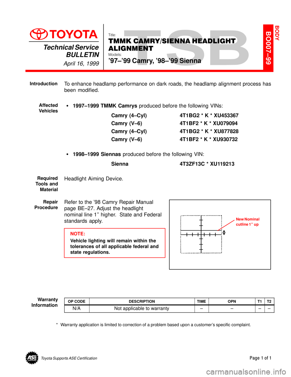
Headlight Aiming Device.
Refer to the '98 Camry Repair Manual
page BE±27. Adjust the headlight
nominal line 1'' higher. State and Federal
standards apply.
NOTE:
Vehicle lighting will remain within the
tolerances of all applicable federal and
state regulations.
OP CODEDESCRIPTIONTIMEOPNT1T2
N/ANot applicable to warranty±±±±
* Warranty application is limited to correction of a problem based upon a customer's specific complaint.
BODY
Introduction
Affected
Vehicles
Required
Tools and
Material
Repair
Procedure
New Nominal
cutline 1'' up
Warranty
Information
Page 3695 of 4592
1997 CAMRY DOOR MIRROR INSTALLATIONPage 2 of 2
INSTALLATION PROCEDURES (Cont'd):
4. Tighten the three mirror mounting nuts A , B
and C for vehicles without a tweeter.
Torque: 5.5 N.m (56 kgf.cm, 49 in.lbf)
Connect the mirror wire.
5. Tighten the two mirror mounting nuts A and
B for vehicles with a tweeter.
Torque: 5.5 N.m (56 kgf.cm, 49 in.lbf)
Connect the mirror wire.
While lightly pulling the mirror wire
backward, install the tweeter and tighten
nut C.
Torque: 5.5 N.m (56 kgf.cm, 49 in.lbf)
NOTE:Check that the mirror wire is free
from the tweeter bracket.
6. Check the following items:
�There is no clearance between the door
mirror base and the door molding lip.
�The door frame molding lip is not tucked
under the mirror base.
7. Install the front door lower frame bracket
garnish.
8. Install the black cap onto the nut.
BC
A
B
A
C
Molding Lip
Mirror Base
Garnish
Cap
Page 3709 of 4592
DOOR GLASS DISPLACEMENT FIELD FIX ± BO012±99 September 3, 1999
Page 2 of 2
Refer to 1998 Camry Repair Manual (Vol. 2) Pages BO±11±14.
1. Remove the front door trim to gain access to the window components.
2. Inspect the front and rear lower frames and the door glass run for damage as a result
of the glass being displaced.
�In cases of slight deformation of window frames, reform as necessary.
If significantly deformed or damaged, replace the frame.
�Replace the window run if cut, torn, mutilated, etc.
3. Replace any damaged parts.
4. Remove front lower frame from the door and attach the self±adhesive rubber stopper
(P/N 67212±AA010) 120 mm from the top of the frame as shown below.
NOTE:
To insure proper adhesion of the self±adhesive rubber stopper, the surface of the
frame must be cleaned to remove any foreign material.
5. Reinstall the front lower frame, door glass run, and door trim.
Stopper
67212±AA010
(50 x 12 x 4.76 mm)
(double sided tape)
120 mm
Repair
Procedure
Page 3711 of 4592

DOOR MIRROR INSTALLATION ± BO015-00 March 24, 2000
Page 2 of 2
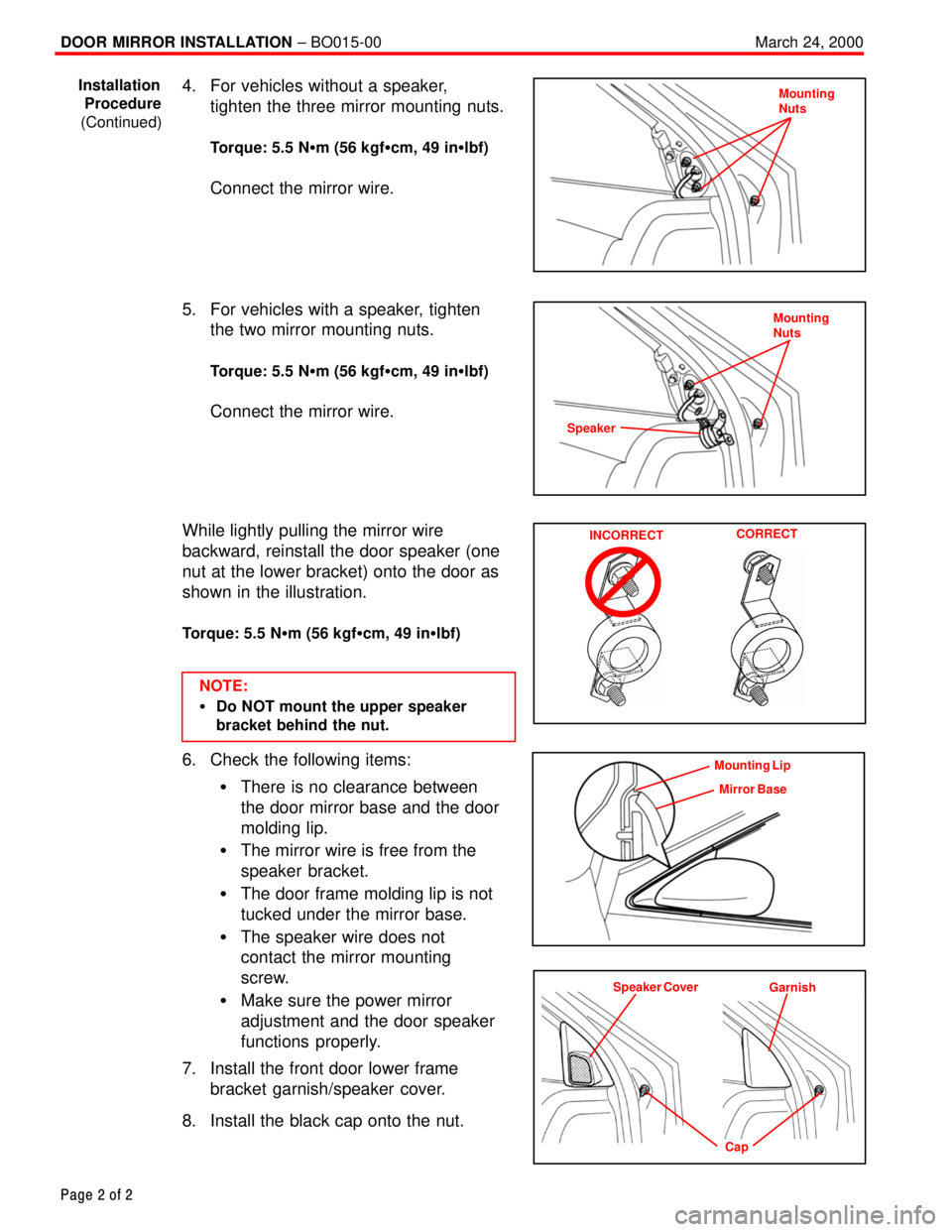
4. For vehicles without a speaker,
tighten the three mirror mounting nuts.
Torque: 5.5 N�m (56 kgf�cm, 49 in�lbf)
Connect the mirror wire.
5. For vehicles with a speaker, tighten
the two mirror mounting nuts.
Torque: 5.5 N�m (56 kgf�cm, 49 in�lbf)
Connect the mirror wire.
While lightly pulling the mirror wire
backward, reinstall the door speaker (one
nut at the lower bracket) onto the door as
shown in the illustration.
Torque: 5.5 N�m (56 kgf�cm, 49 in�lbf)
NOTE:
�Do NOT mount the upper speaker
bracket behind the nut.
6. Check the following items:
�There is no clearance between
the door mirror base and the door
molding lip.
�The mirror wire is free from the
speaker bracket.
�The door frame molding lip is not
tucked under the mirror base.
�The speaker wire does not
contact the mirror mounting
screw.
�Make sure the power mirror
adjustment and the door speaker
functions properly.
7. Install the front door lower frame
bracket garnish/speaker cover.
8. Install the black cap onto the nut.
Installation
Procedure
(Continued)Mounting
Nuts
Mounting
Nuts
Speaker
INCORRECTCORRECT
Mounting Lip
Mirror Base
Speaker Cover
Garnish
Cap
Page 3770 of 4592
During vehicle processing by Dealers, care must be taken to avoid applying undercoating in the
area surrounding the Oxygen Sensors. Application of undercoating on or near the Oxygen Sensors
can cause insufficient air to flow around the sensor, and inaccurate information storage by the ECM.
If this condition occurs, the Malfunction Indicator Light (MIL) may illuminate.
UNDERCOATING ON OXYGEN SENSORSPage 1 of 1
OCTOBER 11, 1996 ENGINE
EG003-96
ALL MODELS
Sub Oxygen Sensor
Main Oxygen SensorCenter Pipe to Muffler
Avoid undercoating this area
Front Pipe to Manifold