Page 2642 of 4592
CYLINDER BLOCK
EM±91
1263 Author�: Date�:
13. REMOVE ENGINE BALANCER
(a) Uniformly loosen and remove the 6 bolts in several")
S03789
1
4
6
5
2
3
N00991
P03166
N00924
N00993
± ENGINE MECHANICAL (5S±FE)CYLINDER BLOCK
EM±91
1263 Author�: Date�:
13. REMOVE ENGINE BALANCER
(a) Uniformly loosen and remove the 6 bolts in several
passes, in the sequence shown.
(b) Remove the engine balancer and spacers.
14. CHECK CONNECTING ROD THRUST CLEARANCE
Using a dial indicator, measure the thrust clearance while mov-
ing the connecting rod back and forth.
Standard thrust clearance:
0.160 ± 0.312 mm (0.0063 ± 0.0123 in.)
Maximum thrust clearance: 0.35 mm (0.0138 in.)
If the thrust clearance is greater than maximum, replace the
connecting rod assembly. If necessary, replace the crankshaft.
15. REMOVE CONNECTING ROD CAPS AND CHECK OIL
CLEARANCE
(a) Check the matchmarks on the connecting rod and cap to
ensure correct reassembly.
(b) Remove the 2 connecting rod cap nuts.
(c) Using a plastic±faced hammer, lightly tap the connecting
rod bolts and lift off the connecting rod cap.
HINT:
Keep the lower bearing inserted with the connecting rod cap.
(d) Cover the connecting rod bolts with a short piece of hose
to protect the crankshaft from damage.
(e) Clean the crank pin and bearing.
(f) Check the crank pin and bearing for pitting and scratches.
If the crank pin or bearing is damaged, replace the bearings. If
necessary, grind or replace the crankshaft.
Page 2647 of 4592
A06590
A06589
A06587
A01774
A01775
EM±96
± ENGINE MECHANICAL (5S±FE)CYLINDER BLOCK
1268 Author�: Date�:
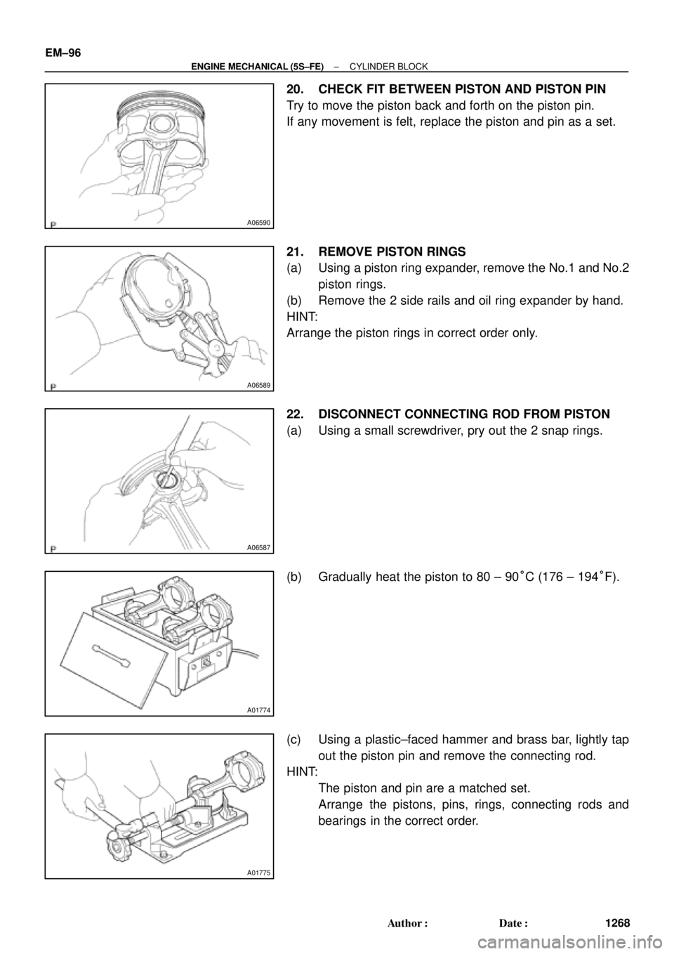
20. CHECK FIT BETWEEN PISTON AND PISTON PIN
Try to move the piston back and forth on the piston pin.
If any movement is felt, replace the piston and pin as a set.
21. REMOVE PISTON RINGS
(a) Using a piston ring expander, remove the No.1 and No.2
piston rings.
(b) Remove the 2 side rails and oil ring expander by hand.
HINT:
Arrange the piston rings in correct order only.
22. DISCONNECT CONNECTING ROD FROM PISTON
(a) Using a small screwdriver, pry out the 2 snap rings.
(b) Gradually heat the piston to 80 ± 90°C (176 ± 194°F).
(c) Using a plastic±faced hammer and brass bar, lightly tap
out the piston pin and remove the connecting rod.
HINT:
�The piston and pin are a matched set.
�Arrange the pistons, pins, rings, connecting rods and
bearings in the correct order.
Page 2660 of 4592
CYLINDER BLOCK
EM±109
1281 Author�: Date�:
(b) Align the bearing claw with the claw groove of the")
P03177
Mark
1, 2, 3, 4, or 5
P05354
P03173
S06012
P00104
1
10
735
84269
± ENGINE MECHANICAL (5S±FE)CYLINDER BLOCK
EM±109
1281 Author�: Date�:
(b) Align the bearing claw with the claw groove of the main
bearing cap, and push in the 5 lower bearings.
HINT:
A number is marked on each main bearing cap to indicate the
installation position.
5. INSTALL UPPER THRUST WASHERS
Install the 2 thrust washers under the No.3 journal position of
the cylinder block with the oil grooves facing outward.
6. PLACE CRANKSHAFT ON CYLINDER BLOCK
7. INSTALL MAIN BEARING CAPS AND LOWER
THRUST WASHERS
(a) Install the 2 thrust washers on the No.3 bearing cap with
the grooves facing outward.
(b) Install the 5 main bearing caps in their proper locations.
HINT:
Each bearing cap has a number and front mark.
(c) Apply a light coat of engine oil on the threads and under
the heads of the main bearing cap bolts.
(d) Install and uniformly tighten the 10 bolts of the main bear-
ing cap in several passes, in the sequence shown.
Torque: 59 N´m (600 kgf´cm, 43 ft´lbf)
(e) Check that the crankshaft turns smoothly.
8. CHECK CRANKSHAFT THRUST CLEARANCE
(See page EM±86)
Page 2661 of 4592

Front
N01001
Front Mark
(Protrusion)
Z19381
EM±110
± ENGINE MECHANICAL (5S±FE)CYLINDER BLOCK
1282 Author�: Date�:
9. INSTALL PISTON AND CONNECTING ROD AS-
SEM")
EM2082
A06614
Push Front Mark
(Cavity)
Front
N01001
Front Mark
(Protrusion)
Z19381
EM±110
± ENGINE MECHANICAL (5S±FE)CYLINDER BLOCK
1282 Author�: Date�:
9. INSTALL PISTON AND CONNECTING ROD AS-
SEMBLES
(a) Cover the connecting rod bolts with a short piece of hose
to protect the crankshaft from damage.
(b) Using a piston ring compressor, push the correctly num-
bered piston and connecting rod assemblies into each
cylinder with the front mark of the piston facing forward.
10. PLACE CONNECTING ROD CAP ON CONNECTING
ROD
(a) Match the numbered connecting rod cap with the con-
necting rod.
(b) Install the connecting rod cap with the front mark facing
forward.
11. INSTALL CONNECTING ROD CAP NUTS
HINT:
�The cap nuts are tightened in 2 progressive steps (steps
(b) and (d)).
�If any one of the connecting rod bolts is broken or de-
formed, replace it.
(a) Apply a light coat of engine oil on the threads and under
the nuts of the connecting rod cap.
(b) Install and alternately tighten the 2 cap nuts in several
passes.
Torque: 25 N´m (250 kgf´cm, 18 ft´lbf)
If any one of the cap nuts does not meet the torque specifica-
tion, replace the connecting rod bolt and cap nut as a set.
Page 2671 of 4592

SST (B) SST (B)
SST (A)
P12920
SST (B)
Magnetic Finger
EM0494
EM±6
± ENGINE MECHANICAL (1MZ±FE)VALVE CLEARANCE
1292 Author�: Date�:
(3) Using SS")
Z09456
Front of No.1 and No.2 Cylinder
OthersSST (A)
SST (B) SST (B)
SST (A)
P12920
SST (B)
Magnetic Finger
EM0494
EM±6
± ENGINE MECHANICAL (1MZ±FE)VALVE CLEARANCE
1292 Author�: Date�:
(3) Using SST (A), press down the valve lifter and place
SST (B) between the camshaft and valve lifter. Re-
move SST (A).
SST 09248±55040 (09248±05410, 09248±05420)
HINT:
�Apply SST (B) at a slight angle on the side marked with
º9º or º7º, at the position shown in the illustration.
�When SST (B) is inserted too deeply, it will get pinched by
the shim. To prevent it from being stuck, insert it gently
from the intake side, at a slight angle.
�Using a small screwdriver and magnetic finger, remove
the adjusting shim.
(b) Determine the replacement adjusting shim size according
to these Formula or Charts:
(1) Using a micrometer, measure the thickness of the
removed shim.
(2) Calculate the thickness of a new shim so the valve
clearance comes within the specified value.
T .......... Thickness of used shim
A .......... Measured valve clearance
N .......... Thickness of new shim
Intake
N = T + (A ± 0.20 mm (0.008 in.))
Exhaust
N = T + (A ± 0.30 mm (0.012 in.))
(3) Select a new shim with a thickness as close as pos-
sible to the calculated values.
HINT:
Shims are available in 17 sizes in increments of 0.050 mm
(0.0020 in.), from 2.500 mm (0.0984 in.) to 3.300 mm (0.1299
in.).
Page 2675 of 4592
IGNITION TIMING
1296 Author�: Date�:
IGNITION TIMING
INSPECTION
1. WARM UP ENGINE
Allow")
EM04L±03
S05358
Hand±Held Tester TOYOTA
S04529
E1DLC1
SST
TE1
DLC1
A06644
EM±10
± ENGINE MECHANICAL (1MZ±FE)IGNITION TIMING
1296 Author�: Date�:
IGNITION TIMING
INSPECTION
1. WARM UP ENGINE
Allow the engine to warm up to normal operating temperature.
2. CONNECT TOYOTA HAND±HELD TESTER OR
OBDII SCAN TOOL
(a) Connect a TOYOTA hand±held tester or OBDII scan tool
to the DLC3.
(b) Please refer to the TOYOTA hand±held tester or OBDII
scan tool operator's manual for further details.
3. CONNECT TIMING LIGHT TO ENGINE
Connect the tester probe of a timing light to the No.1 high±ten-
sion cord for No.4 cylinder.
4. CHECK IDLE SPEED
(a) Race the engine speed at 2,500 rpm for approx. 90 se-
conds.
(b) Check the idle speed.
Idle speed: 700 ± 50 rpm
5. INSPECT IGNITION TIMING
(a) Using SST, connect terminals TE1 and E1 of the DLC1.
SST 09843±18020
(b) Using a timing light, check the ignition timing.
Ignition timing: 8 ± 12° BTDC @ idle
(Transmission in neutral position)
(c) Remove the SST from the DLC1.
SST 09843±18020
Page 2676 of 4592
± ENGINE MECHANICAL (1MZ±FE)IGNITION TIMING
EM±11
1297 Author�: Date�:
6. FURTHER CHECK IGNITION TIMING
Ignition timing: 7 ± 24° BTDC @ idle
(Transmission in neutral position)
HINT:
The timing mark moves in a range between 7° and 24°.
7. DISCONNECT TIMING LIGHT FROM ENGINE
8. DISCONNECT TOYOTA HAND±HELD TESTER OR
OBDII SCAN TOOL
Page 2711 of 4592
CYLINDER HEAD
1332 Author�: Date�:
(d) Check the valve overall length.
Standard over")
EM2534
Overall Length
EM0255
P12704
P12729
Width
Z03988
45°
1.0 ± 1.4 mm30° EM±46
± ENGINE MECHANICAL (1MZ±FE)CYLINDER HEAD
1332 Author�: Date�:
(d) Check the valve overall length.
Standard overall length:
Intake95.45 mm (3.5779 in.)
Exhaust95.40 mm (3.7559 in.)
Minimum overall length:
Intake94.95 mm (3.7382 in.)
Exhaust94.90 mm (3.7362 in.)
If the overall length is less than minimum, replace the valve.
(e) Check the surface of the valve stem tip for wear.
If the valve stem tip is worn, resurface the tip with a grinder or
replace the valve.
NOTICE:
Do not grind off more than minimum.
11. INSPECT AND CLEAN VALVE SEATS
(a) Using a 45° carbide cutter, resurface the valve seats.
Remove only enough metal to clean the seats.
(b) Check the valve seating position.
Apply a light coat of prussian blue (or white lead) to the
valve face. Lightly press the valve against the seat. Do not
rotate valve.
(c) Check the valve face and seat for the following:
�If blue appears 360° around the face, the valve is
concentric. If not, replace the valve.
�If blue appears 360° around the valve seat, the
guide and face are concentric. If not, resurface the
seat.
�Check that the seat contact is in the middle of the
valve face with the following width:
1.0 ± 1.4 mm (0.039 ± 0.055 in.)
If not, correct the valve seats as follows:
(1) If the seating is too high on the valve face, use 30°
and 45° cutters to correct the seat.