Page 2505 of 4592
Input SignalIndicator Light
Blinking Pattern
Turn PNP switch
OFF (Shift to posi-
tions except D )LightON
OFFSW ON
SW OFF
± DIAGNOSTICSCRUISE CONTROL SYSTEM
DI±353
INSPECTION PROCEDURE
1 Check starter operation.
CHECK:
Check that the starter operates normally and that the engine starts.
NG Proceed to engine troubleshooting
(See Pub. No. RM654U on page ST±1).
OK
2 Input signal check.
PREPARATION:
See input signal check on page DI±319.
CHECK:
Check the indicator light when shifting into positions except D.
OK:
The indicator light goes off when shifting into posi-
tions except D.
OK Proceed to next circuit inspection shown on
problem symptoms table (See page DI±328).
NG
Page 2512 of 4592
I08465
Battery FL MAINB±G1
F9FL BLOCK
ALT1
F14 R±L
Instrument Panel J/B
2
1D
1K1
GAUGE
B±YIgnition Switch
4 IG1 AM1 2
W
B±RInstrument Panel J/B
1
1BAM12
1K CRUISE MAIN
Indicator Light
(in Combination Meter)
D DJ/CJ3
R±L10 7
C12 C12IE25
OODD
O J/CJ1
4
C16
Cruise Control ECU
PI DI±360
± DIAGNOSTICSCRUISE CONTROL SYSTEM
CRUISE MAIN Indicator Light Circuit
CIRCUIT DESCRIPTION
When the cruise control main switch is turned ON, CRUISE MAIN indicator light lights up.
WIRING DIAGRAM
DI090±20
Page 2529 of 4592
B06539
Disconnect
S05567
Air Engine Stopped
S05566
Engine at
2,500 rpm
Air
± EMISSION CONTROL (5S±FE)EXHAUST GAS RECIRCULATION (EGR) SYSTEM
EC±13
1411 Author�: Date�:
HINT:
As a large amount of exhaust gas enters, the engine will misfire
slightly.
(g) Remove the vacuum gauge, and reconnect the vacuum
hoses to the proper locations.
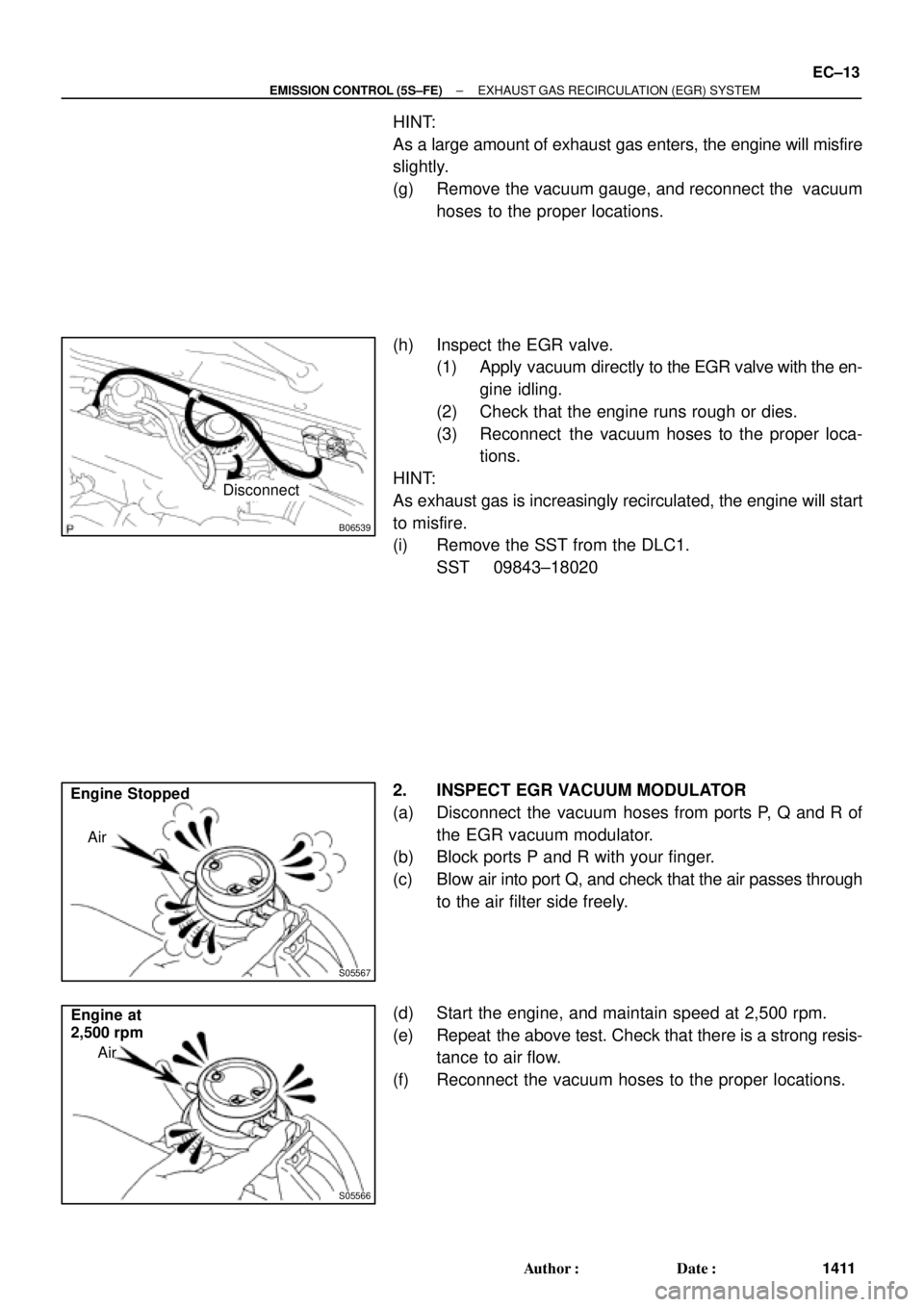
(h) Inspect the EGR valve.
(1) Apply vacuum directly to the EGR valve with the en-
gine idling.
(2) Check that the engine runs rough or dies.
(3) Reconnect the vacuum hoses to the proper loca-
tions.
HINT:
As exhaust gas is increasingly recirculated, the engine will start
to misfire.
(i) Remove the SST from the DLC1.
SST 09843±18020
2. INSPECT EGR VACUUM MODULATOR
(a) Disconnect the vacuum hoses from ports P, Q and R of
the EGR vacuum modulator.
(b) Block ports P and R with your finger.
(c) Blow air into port Q, and check that the air passes through
to the air filter side freely.
(d) Start the engine, and maintain speed at 2,500 rpm.
(e) Repeat the above test. Check that there is a strong resis-
tance to air flow.
(f) Reconnect the vacuum hoses to the proper locations.
Page 2556 of 4592
P03442
2 233 44
44
P13927
Upward
Cam Lobe
Notch
Spark Plug Side
P13988Spark Plug Side SST (A)
SST (B)
P13926
Magnetic
Finger
EM0494
± ENGINE MECHANICAL (5S±FE)VALVE CLEARANCE
EM±5
1177 Author�: Date�:
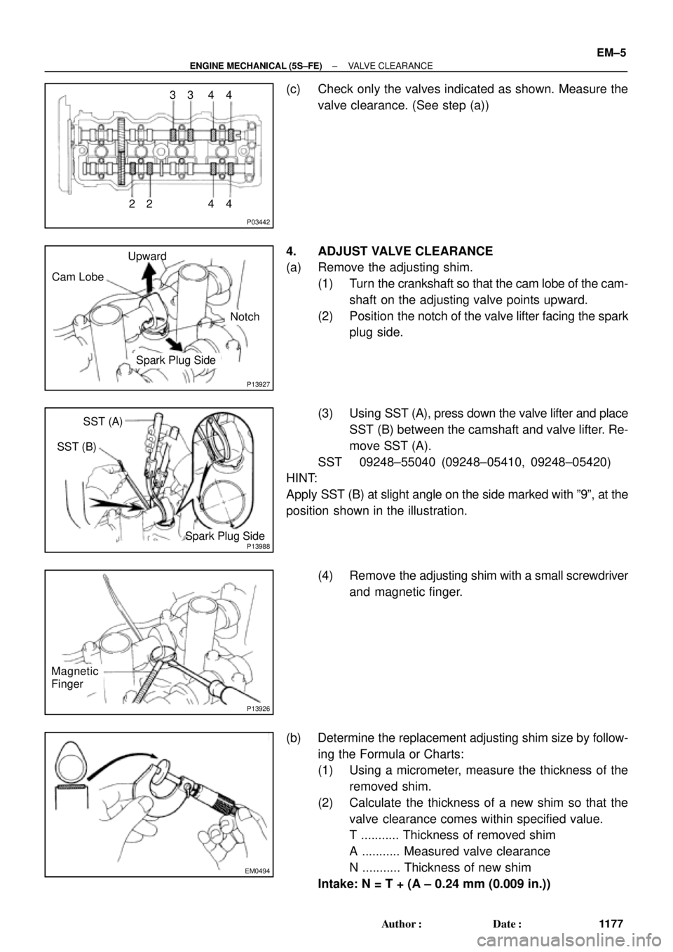
(c) Check only the valves indicated as shown. Measure the
valve clearance. (See step (a))
4. ADJUST VALVE CLEARANCE
(a) Remove the adjusting shim.
(1) Turn the crankshaft so that the cam lobe of the cam-
shaft on the adjusting valve points upward.
(2) Position the notch of the valve lifter facing the spark
plug side.
(3) Using SST (A), press down the valve lifter and place
SST (B) between the camshaft and valve lifter. Re-
move SST (A).
SST 09248±55040 (09248±05410, 09248±05420)
HINT:
Apply SST (B) at slight angle on the side marked with º9º, at the
position shown in the illustration.
(4) Remove the adjusting shim with a small screwdriver
and magnetic finger.
(b) Determine the replacement adjusting shim size by follow-
ing the Formula or Charts:
(1) Using a micrometer, measure the thickness of the
removed shim.
(2) Calculate the thickness of a new shim so that the
valve clearance comes within specified value.
T ........... Thickness of removed shim
A ........... Measured valve clearance
N ........... Thickness of new shim
Intake: N = T + (A ± 0.24 mm (0.009 in.))
Page 2560 of 4592
EM080±03
S05331
A07370
SST
E1
TE1
S05309
± ENGINE MECHANICAL (5S±FE)IGNITION TIMING
EM±9
1181 Author�: Date�:
IGNITION TIMING
INSPECTION
1. WARM UP ENGINE
Allow the engine to warm up to normal operating temperature.
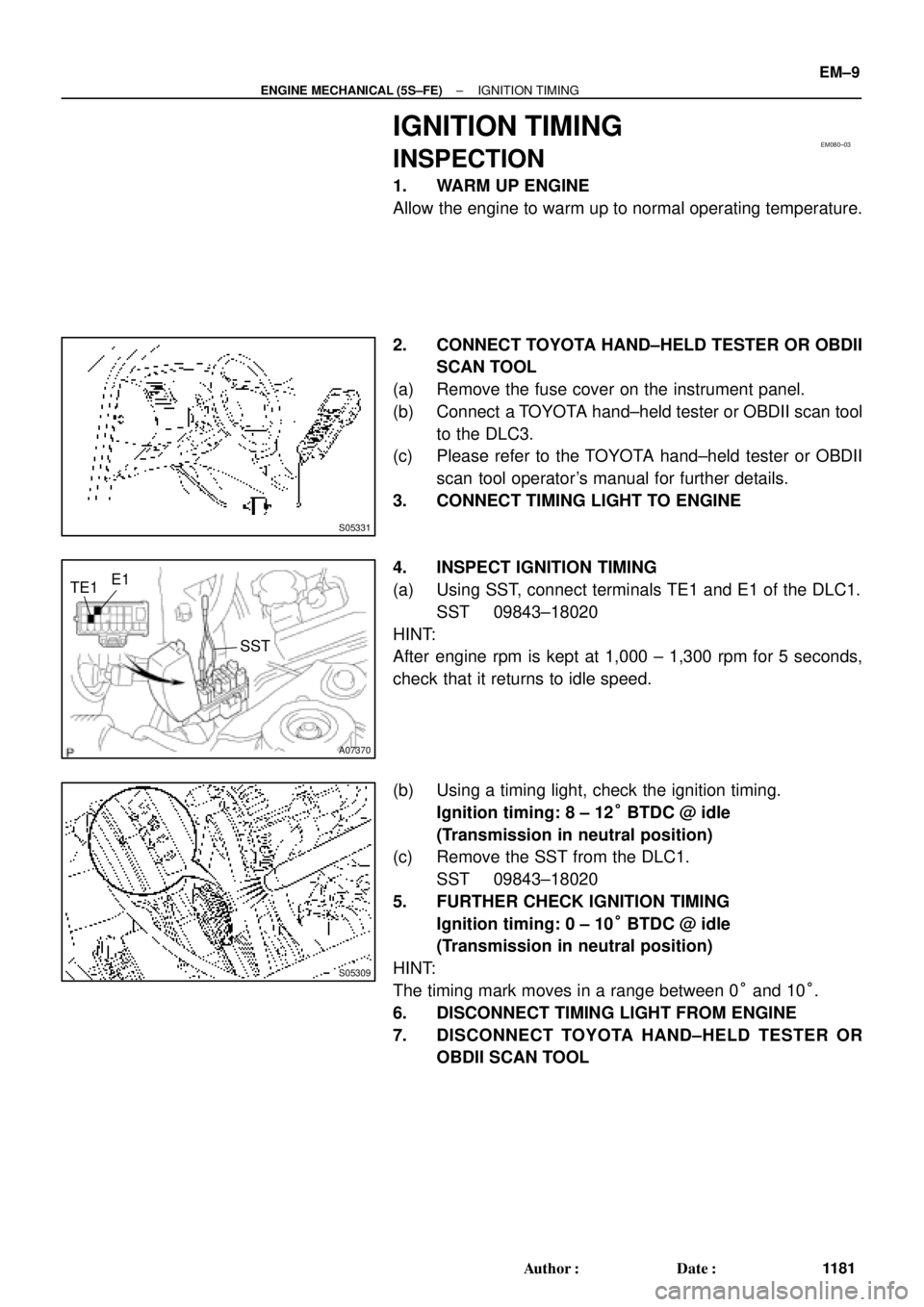
2. CONNECT TOYOTA HAND±HELD TESTER OR OBDII
SCAN TOOL
(a) Remove the fuse cover on the instrument panel.
(b) Connect a TOYOTA hand±held tester or OBDII scan tool
to the DLC3.
(c) Please refer to the TOYOTA hand±held tester or OBDII
scan tool operator's manual for further details.
3. CONNECT TIMING LIGHT TO ENGINE
4. INSPECT IGNITION TIMING
(a) Using SST, connect terminals TE1 and E1 of the DLC1.
SST 09843±18020
HINT:
After engine rpm is kept at 1,000 ± 1,300 rpm for 5 seconds,
check that it returns to idle speed.
(b) Using a timing light, check the ignition timing.
Ignition timing: 8 ± 12° BTDC @ idle
(Transmission in neutral position)
(c) Remove the SST from the DLC1.
SST 09843±18020
5. FURTHER CHECK IGNITION TIMING
Ignition timing: 0 ± 10° BTDC @ idle
(Transmission in neutral position)
HINT:
The timing mark moves in a range between 0° and 10°.
6. DISCONNECT TIMING LIGHT FROM ENGINE
7. DISCONNECT TOYOTA HAND±HELD TESTER OR
OBDII SCAN TOOL
Page 2563 of 4592
P25734
SST
Measuring Point
for Dial Indicator
P06039SST
Z19415
No.1 Balance
Shaft
Mark B
Mark A
No.2 Housing
Z19413
No.1 Balance
Shaft
Mark B
Mark A No.2 Housing EM±12
± ENGINE MECHANICAL (5S±FE)BALANCE SHAFT BACKLASH
1184 Author�: Date�:
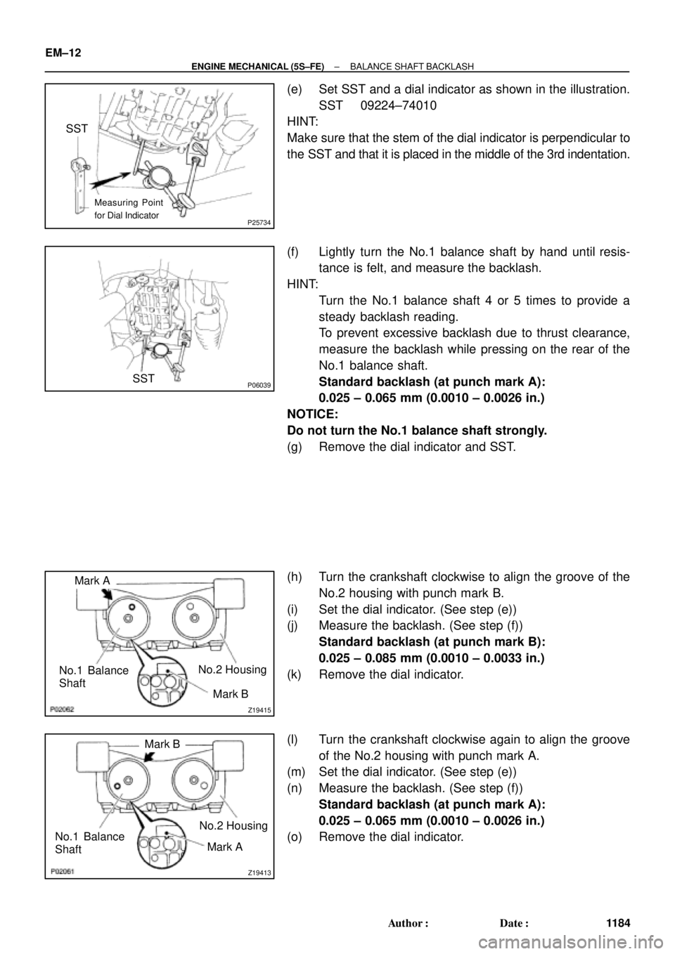
(e) Set SST and a dial indicator as shown in the illustration.
SST 09224±74010
HINT:
Make sure that the stem of the dial indicator is perpendicular to
the SST and that it is placed in the middle of the 3rd indentation.
(f) Lightly turn the No.1 balance shaft by hand until resis-
tance is felt, and measure the backlash.
HINT:
�Turn the No.1 balance shaft 4 or 5 times to provide a
steady backlash reading.
�To prevent excessive backlash due to thrust clearance,
measure the backlash while pressing on the rear of the
No.1 balance shaft.
Standard backlash (at punch mark A):
0.025 ± 0.065 mm (0.0010 ± 0.0026 in.)
NOTICE:
Do not turn the No.1 balance shaft strongly.
(g) Remove the dial indicator and SST.
(h) Turn the crankshaft clockwise to align the groove of the
No.2 housing with punch mark B.
(i) Set the dial indicator. (See step (e))
(j) Measure the backlash. (See step (f))
Standard backlash (at punch mark B):
0.025 ± 0.085 mm (0.0010 ± 0.0033 in.)
(k) Remove the dial indicator.
(l) Turn the crankshaft clockwise again to align the groove
of the No.2 housing with punch mark A.
(m) Set the dial indicator. (See step (e))
(n) Measure the backlash. (See step (f))
Standard backlash (at punch mark A):
0.025 ± 0.065 mm (0.0010 ± 0.0026 in.)
(o) Remove the dial indicator.
Page 2596 of 4592
EM2534
Overall Length
EM0255
P03272
45° Carbide
Cutter
Z00055
Width
± ENGINE MECHANICAL (5S±FE)CYLINDER HEAD
EM±45
1217 Author�: Date�:
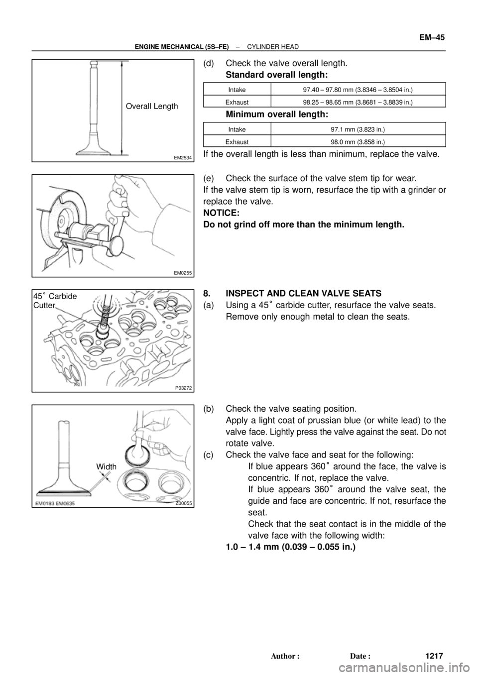
(d) Check the valve overall length.
Standard overall length:
Intake97.40 ± 97.80 mm (3.8346 ± 3.8504 in.)
Exhaust98.25 ± 98.65 mm (3.8681 ± 3.8839 in.)
Minimum overall length:
Intake97.1 mm (3.823 in.)
Exhaust98.0 mm (3.858 in.)
If the overall length is less than minimum, replace the valve.
(e) Check the surface of the valve stem tip for wear.
If the valve stem tip is worn, resurface the tip with a grinder or
replace the valve.
NOTICE:
Do not grind off more than the minimum length.
8. INSPECT AND CLEAN VALVE SEATS
(a) Using a 45° carbide cutter, resurface the valve seats.
Remove only enough metal to clean the seats.
(b) Check the valve seating position.
Apply a light coat of prussian blue (or white lead) to the
valve face. Lightly press the valve against the seat. Do not
rotate valve.
(c) Check the valve face and seat for the following:
�If blue appears 360° around the face, the valve is
concentric. If not, replace the valve.
�If blue appears 360° around the valve seat, the
guide and face are concentric. If not, resurface the
seat.
�Check that the seat contact is in the middle of the
valve face with the following width:
1.0 ± 1.4 mm (0.039 ± 0.055 in.)
Page 2603 of 4592
EM0YM±01
P03274
SST
Z02903
Intake Exhaust
Gray
Black
P03265
SST
P03276
EM±52
± ENGINE MECHANICAL (5S±FE)CYLINDER HEAD
1224 Author�: Date�:
REASSEMBLY
HINT:
�Thoroughly clean all parts to be assembled.
�Before installing the parts, apply new engine oil to all slid-
ing and rotating surfaces.
�Replace all gaskets and oil seals with new ones.
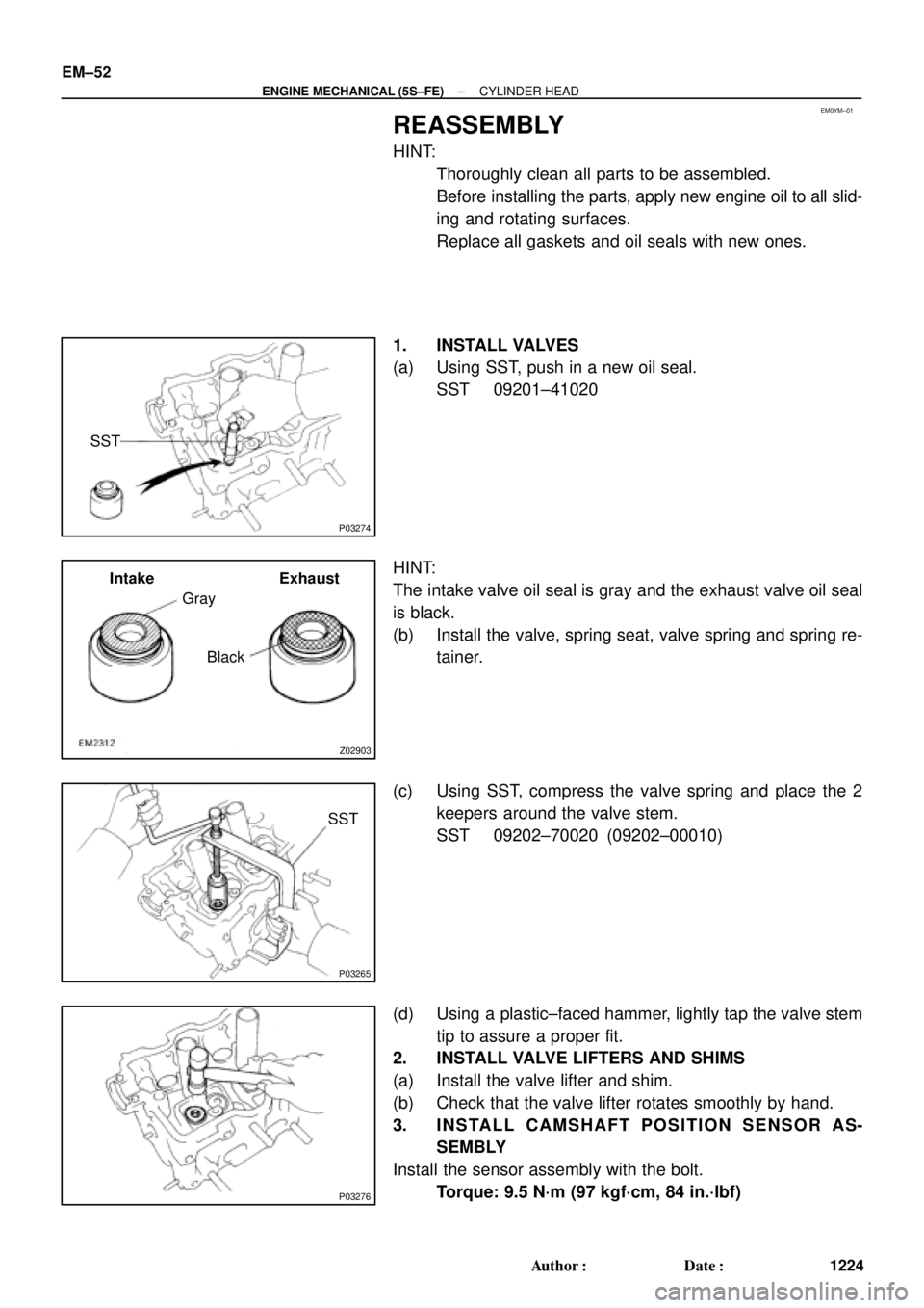
1. INSTALL VALVES
(a) Using SST, push in a new oil seal.
SST 09201±41020
HINT:
The intake valve oil seal is gray and the exhaust valve oil seal
is black.
(b) Install the valve, spring seat, valve spring and spring re-
tainer.
(c) Using SST, compress the valve spring and place the 2
keepers around the valve stem.
SST 09202±70020 (09202±00010)
(d) Using a plastic±faced hammer, lightly tap the valve stem
tip to assure a proper fit.
2. INSTALL VALVE LIFTERS AND SHIMS
(a) Install the valve lifter and shim.
(b) Check that the valve lifter rotates smoothly by hand.
3. INSTALL CAMSHAFT POSITION SENSOR AS-
SEMBLY
Install the sensor assembly with the bolt.
Torque: 9.5 N´m (97 kgf´cm, 84 in.´lbf)