Page 2465 of 4592
H08301H10309
LG±R P±B
B
BJ2 Junction
ConnectorAirbag Sensor
Assembly
C519
Tc
11
LG±R 11
Tc
E1DLC1
3 BR
A
BR
ECEC BR A
Junction
Connector
6
J6B
J7 C
BR 3
E1Tc DLC2 LG±R
4
B IG3
IG3
BR
J20
Junction Connector
A A BR J20
Junction Connector
± DIAGNOSTICSSUPPLEMENTAL RESTRAINT SYSTEM
DI±313
Tc Terminal Circuit
CIRCUIT DESCRIPTION
By connecting terminals Tc and E1 of the DLC1 the airbag sensor assembly is set in the DTC output mode.
The DTCs are displayed by blinking the SRS warning light.
WIRING DIAGRAM
DI1BQ±12
Page 2466 of 4592
AB0117AB0118AB0119H10313H10315
LOCK ACC
ON
or
AB0118
R14305AB0119
H00030
ACCON
or
E1
Tc
(+) (±)
DI±314
± DIAGNOSTICSSUPPLEMENTAL RESTRAINT SYSTEM
INSPECTION PROCEDURE
If the DTC is not displayed, do the following troubleshooting.
1 Does SRS warning light up for approx. 6 seconds?
PREPARATION:
Check operation of the SRS warning light after ignition switch
is turned from LOCK position to ACC or ON position.
NO Check SRS warning light system.
(See page DI±223)
YES
2 Check voltage between terminals Tc and E1 of DLC1.
PREPARATION:
Turn ignition switch to ACC or ON.
CHECK:
Measure the voltage between terminals Tc and E1 of DLC1.
OK:
Voltage: 10 ± 14 V
OK Go to step 4.
NG
Page 2467 of 4592

(±)
AB0117 AB0118 AB0119H01302H01303
LOCK
ACCON
or
Airbag Sensor Assembly
Tc
± DIAGNOSTICSSUPPLEMENTAL RESTRAINT SYSTEM
DI±315
3 Check voltage between term")
AB0118
R14304AB0119
H00031
ACCON
orTc
(+)
(±)
AB0117 AB0118 AB0119H01302H01303
LOCK
ACCON
or
Airbag Sensor Assembly
Tc
± DIAGNOSTICSSUPPLEMENTAL RESTRAINT SYSTEM
DI±315
3 Check voltage between terminal Tc of DLC1 and body ground.
CHECK:
Measure the voltage between terminal Tc of DLC1 and body
ground.
OK:
Voltage: 10 ± 14 V
OK Check harness between terminal E1 of DLC1
and body ground.
NG
4 Check airbag sensor assembly.
PREPARATION:
(a) Turn ignition switch to LOCK.
(b) Disconnect negative (±) terminal cable from the battery,
and wait at least for 90 seconds.
(c) Disconnect the airbag sensor assembly connector.
(d) Insert service wire into terminal Tc from back side as
shown in the illustration.
(e) Connect the airbag sensor assembly connector with ser-
vice wire.
(f) Connect negative (±) terminal cable to the battery.
(g) Turn ignition switch to ACC or ON and wait at least for 20
seconds.
(h) Connect service wire of terminal Tc to body ground.
CHECK:
Check operation of SRS warning light.
OK:
SRS waning light comes on.
NOTICE:
Pay due attention to the terminal connecting position to
avoid a malfunction.
OK Check harness between the airbag sensor as-
sembly and DLC1.
NG
Replace airbag sensor assembly.
Page 2470 of 4592

DI08G±09
CRUISE CONTROL SYSTEM Check Sheet
Inspector 's name:
Customer 's Name
Date VehicleRegistration No.
Registration Year
Frame No.
Odometer Reading / /km
Mile
Condition of
Problem Occurrence
Date of Problem
How Often does
Occurrence
Problem Occurs
Vehicle Speed when
Problem Occurred / /
Continuous Intermittent ( Times a day)
km
Mile Brought in
Auto cancel
occurs� Driving condition
� City driving � Freeway � Up hill � Down hill
� After cancel occurred, did the driver activate cruise control
again?
� Yes � No
� Cancel does not
occur� With brake ON
� Except D position shift � At 40 km/h (25 mph) or less
� When control SW turns to CANCEL position
� Cruise control
malfunction� Slip to acceleration side
� Slip to deceleration side
� Hunting occurs
� O/D cut off does not occur
� O/D does not return
� Switch
malfunction� SET � ACCEL � COAST � RESUME � CANCEL
�
� Remains ON � Does not light up � Blinking Symptoms
DTC Check1st Time2nd Time
� Normal Code � Malfunction Code (Code )
� Normal Code � Malfunction Code (Code ) DI±318
± DIAGNOSTICSCRUISE CONTROL SYSTEM
CUSTOMER PROBLEM ANALYSIS CHECK
Page 2471 of 4592
 Check the i")
I00279CRUISE MAIN Indicator Light
DI1KS±04
BE4034
Indicator light
1.5 sec.0.5 sec.
ON
OFF
I00169
DLC2
Tc E 1
± DIAGNOSTICSCRUISE CONTROL SYSTEM
DI±319
PRE±CHECK
1. DIAGNOSIS SYSTEM
(a) Check the indicator.
(1) Turn the ignition switch ON.
(2) Check that the CRUISE MAIN indicator light comes
ON when the cruise control main switch is turned
ON, and that the indicator light goes OFF when the
main switch is turned OFF.
HINT:
If the indicator check result is not normal, proceed to trouble-
shooting (See page BE±1) for the combination meter section.
(b) Check the DTC.
HINT:
If a malfunction occurs in the No. 1 vehicle speed sensor or ac-
tuator, etc. during cruise control driving, the ECU actuates
AUTO CANCEL of the cruise control and turns on and off the
CRUISE MAIN indicator light to inform the driver of a malfunc-
tion. At the same time, the malfunction is stored in memory as
a DTC.
(c) Output of DTC using diagnosis check wire.
(1) Turn the ignition switch ON.
(2) Using SST, connect terminals Tc and E
1 of DLC2.
SST 09843±18020
(3) Read the DTC on the CRUISE MAIN indicator light.
Page 2475 of 4592

(2)
(1)
No.Operation MethodCRUISE MAIN Indicator Light
Blinking PatternDiagnosis
1 Turn SET/COAST switch ON
2Turn RES/ACC switch ON
3Turn CANCEL switch ON
Turn stop light switch ON
Depress")
N17520
(1)
(2)
(1)
No.Operation MethodCRUISE MAIN Indicator Light
Blinking PatternDiagnosis
1 Turn SET/COAST switch ON
2Turn RES/ACC switch ON
3Turn CANCEL switch ON
Turn stop light switch ON
Depress brake pedal
Turn PNP switch OFF
(Shift to except D position)
4Drive at about 40 km/h
(25 mph)or higher
Drive at about 40 km/h
(25 mph) or below
LightON
OFF
LightON
OFF
LightON
OFFSwitch ON
Switch OFF
LightON
OFFSwitch OFF
Switch ONSET/COAST switch circuit
is normal
RES/ACC switch circuit
is normal
CANCEL switch circuit
is normal
Stop light switch circuit
is normal
PNP switch circuit is
normal
Vehicle Speed Sensor is
normal
LightON
OFF LightON
OFF
1sec.
0.25 sec.0.25 sec.
± DIAGNOSTICSCRUISE CONTROL SYSTEM
DI±323
5. INPUT SIGNAL CHECK
HINT:
(1): For check No.1 ± No.3
�Turn ignition switch ON.
(2): For check No.4
�Jack up the vehicle.
�Start the engine.
�Shift to D position.
(a) Pull the control switch to SET/COAST or RES/ACC posi-
tion and hold it down or up (1).
(b) Push the main switch ON (2).
(c) Check that the CRUISE MAIN indicator light blinks twice
or 3 times repeatedly after 3 seconds.
(d) Turn the SET/COAST or RES/ACC switch OFF.
(e) Operate each switch as listed in the table below.
(f) Read the blinking pattern of the CRUISE MAIN indicator
light.
(g) After performing the check, turn the main switch OFF.
HINT:
When 2 or more signals are input to the ECU, the lowest num-
bered code will be displayed first.
Page 2476 of 4592

DI08I±09
DI±324
± DIAGNOSTICSCRUISE CONTROL SYSTEM
DIAGNOSTIC TROUBLE CODE CHART
If a malfunction code is displayed during the DTC check, check the circuit listed for that code in the table
below and proceed to the appropriate page.
DTC No.
(See Page)Circuit InspectionTrouble Area
11, 15
(DI±329)Actuator Motor Circuit
�Actuator motor
�Harness or connector between cruise control ECU and
actuator motor
�Cruise control ECU
12
(DI±331)Actuator Magnetic Clutch Circuit
�STOP Fuse
�Stop light switch
�Actuator magnetic clutch
�Harness or connector between cruise control ECU and
actuator magnetic clutch, actuator magnetic clutch and body
ground
�Cruise control ECU
14
(DI±334)Actuator Mechanical Malfunction�Actuator motor (actuator lock: motor, arm)
�Cruise control ECU
21
(DI±336)Open in Vehicle Speed Sensor Circuit
�Combination meter
�Harness or connector between cruise control ECU and com-
bination meter, combination meter and vehicle speed sensor
�Vehicle speed sensor
�Cruise control ECU
23
(DI±339)Vehicle Speed Signal Abnormal�Vehicle speed sensor
�Cruise control ECU
32
(DI±340)Control Switch Circuit
�Cruise control switch
�Harness or connector between cruise control ECU and cruise
control switch, cruise control switch and body ground
�Cruise control ECU
41Cruise control ECU�Cruise control ECU
42Source voltage drop�Power source
51
(DI±343)Idle Signal Circuit
�Throttle position sensor
�Harness or connector between ECM and throttle position
sensor
�Harness or connector between cruise control ECU and ECM
�Cruise control ECU
Page 2477 of 4592
DI08J±09
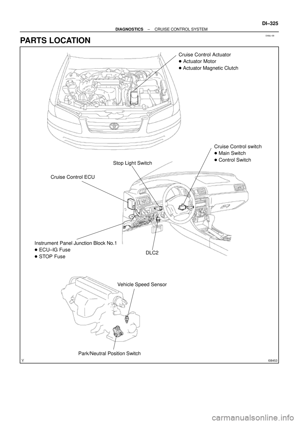
I08453
Stop Light SwitchCruise Control Actuator
� Actuator Motor
� Actuator Magnetic Clutch
Cruise Control ECUCruise Control switch
� Main Switch
� Control Switch
DLC2 Instrument Panel Junction Block No.1
� ECU±IG Fuse
� STOP Fuse
Park/Neutral Position SwitchVehicle Speed Sensor
± DIAGNOSTICSCRUISE CONTROL SYSTEM
DI±325
PARTS LOCATION

 (±)
DI±314
± DIAGNOSTICSSUPPLEMENTAL RESTRAINT SYSTEM
INSPECTION PROCEDURE
If the DTC is not displayed, d")