Page 2604 of 4592
EM08D±04
A07355
Z02750
1
10 24 6 839
7 5
S01690
90°
Front
Painted
Mark90°
P03279
± ENGINE MECHANICAL (5S±FE)CYLINDER HEAD
EM±53
1225 Author�: Date�:
INSTALLATION
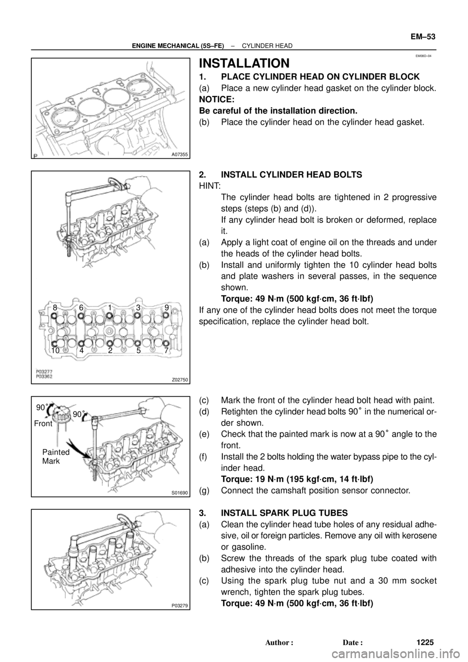
1. PLACE CYLINDER HEAD ON CYLINDER BLOCK
(a) Place a new cylinder head gasket on the cylinder block.
NOTICE:
Be careful of the installation direction.
(b) Place the cylinder head on the cylinder head gasket.
2. INSTALL CYLINDER HEAD BOLTS
HINT:
�The cylinder head bolts are tightened in 2 progressive
steps (steps (b) and (d)).
�If any cylinder head bolt is broken or deformed, replace
it.
(a) Apply a light coat of engine oil on the threads and under
the heads of the cylinder head bolts.
(b) Install and uniformly tighten the 10 cylinder head bolts
and plate washers in several passes, in the sequence
shown.
Torque: 49 N´m (500 kgf´cm, 36 ft´lbf)
If any one of the cylinder head bolts does not meet the torque
specification, replace the cylinder head bolt.
(c) Mark the front of the cylinder head bolt head with paint.
(d) Retighten the cylinder head bolts 90° in the numerical or-
der shown.
(e) Check that the painted mark is now at a 90° angle to the
front.
(f) Install the 2 bolts holding the water bypass pipe to the cyl-
inder head.
Torque: 19 N´m (195 kgf´cm, 14 ft´lbf)
(g) Connect the camshaft position sensor connector.
3. INSTALL SPARK PLUG TUBES
(a) Clean the cylinder head tube holes of any residual adhe-
sive, oil or foreign particles. Remove any oil with kerosene
or gasoline.
(b) Screw the threads of the spark plug tube coated with
adhesive into the cylinder head.
(c) Using the spark plug tube nut and a 30 mm socket
wrench, tighten the spark plug tubes.
Torque: 49 N´m (500 kgf´cm, 36 ft´lbf)
Page 2606 of 4592
P03369
80 ±115°
Knock
Pin
EM3373
2 ± 3 mm
(0.08 ± 0.12 in.)
Seal
Packing
P03370
P03371
17
5
3
98
2
6
4
10
P03372
SST
± ENGINE MECHANICAL (5S±FE)CYLINDER HEAD
EM±55
1227 Author�: Date�:
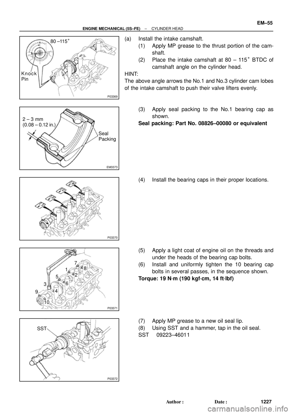
(a) Install the intake camshaft.
(1) Apply MP grease to the thrust portion of the cam-
shaft.
(2) Place the intake camshaft at 80 ± 115° BTDC of
camshaft angle on the cylinder head.
HINT:
The above angle arrows the No.1 and No.3 cylinder cam lobes
of the intake camshaft to push their valve lifters evenly.
(3) Apply seal packing to the No.1 bearing cap as
shown.
Seal packing: Part No. 08826±00080 or equivalent
(4) Install the bearing caps in their proper locations.
(5) Apply a light coat of engine oil on the threads and
under the heads of the bearing cap bolts.
(6) Install and uniformly tighten the 10 bearing cap
bolts in several passes, in the sequence shown.
Torque: 19 N´m (190 kgf´cm, 14 ft´lbf)
(7) Apply MP grease to a new oil seal lip.
(8) Using SST and a hammer, tap in the oil seal.
SST 09223±46011
Page 2607 of 4592
P03281
10 ± 45°
Knock
Pin
P03373
Assembly
Reference Mark
Timing
Mark
P03374
P03375
1 2
3 410
5 6
8
79 EM±56
± ENGINE MECHANICAL (5S±FE)CYLINDER HEAD
1228 Author�: Date�:
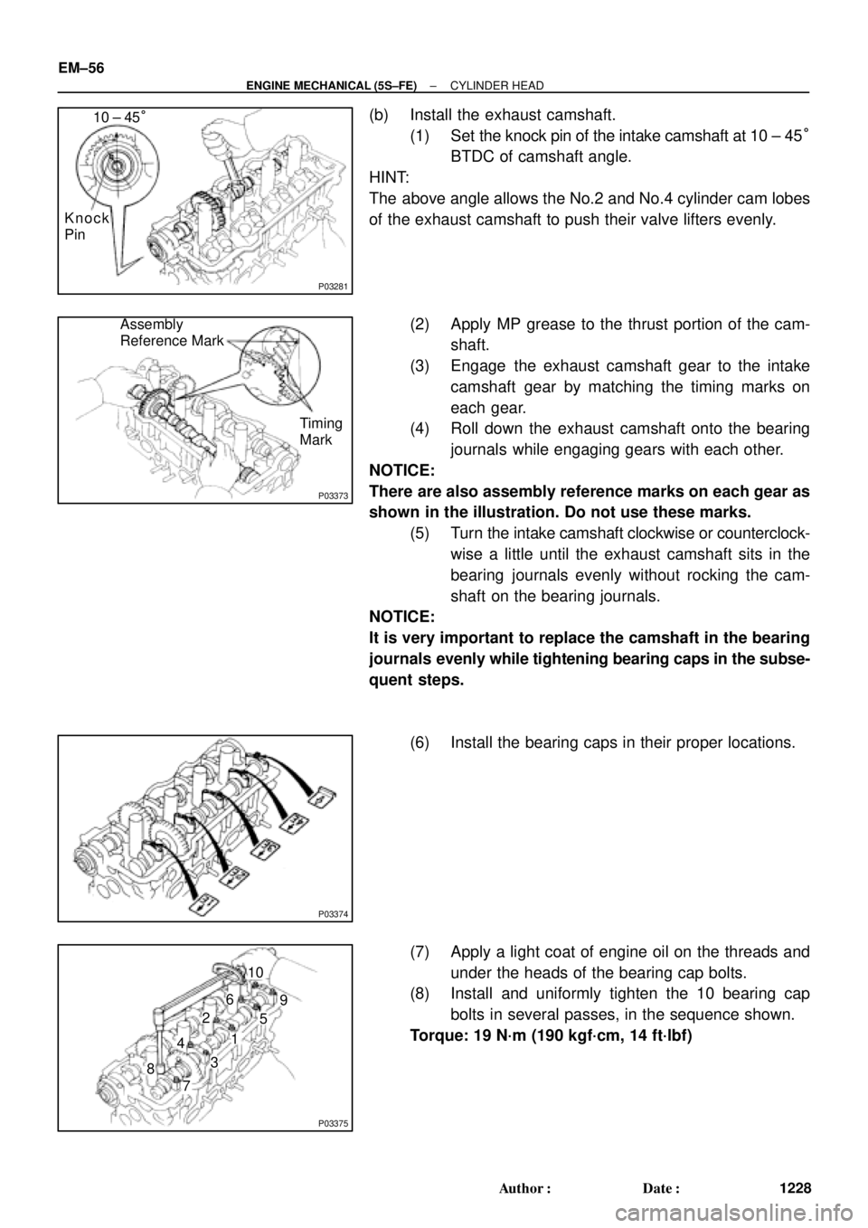
(b) Install the exhaust camshaft.
(1) Set the knock pin of the intake camshaft at 10 ± 45°
BTDC of camshaft angle.
HINT:
The above angle allows the No.2 and No.4 cylinder cam lobes
of the exhaust camshaft to push their valve lifters evenly.
(2) Apply MP grease to the thrust portion of the cam-
shaft.
(3) Engage the exhaust camshaft gear to the intake
camshaft gear by matching the timing marks on
each gear.
(4) Roll down the exhaust camshaft onto the bearing
journals while engaging gears with each other.
NOTICE:
There are also assembly reference marks on each gear as
shown in the illustration. Do not use these marks.
(5) Turn the intake camshaft clockwise or counterclock-
wise a little until the exhaust camshaft sits in the
bearing journals evenly without rocking the cam-
shaft on the bearing journals.
NOTICE:
It is very important to replace the camshaft in the bearing
journals evenly while tightening bearing caps in the subse-
quent steps.
(6) Install the bearing caps in their proper locations.
(7) Apply a light coat of engine oil on the threads and
under the heads of the bearing cap bolts.
(8) Install and uniformly tighten the 10 bearing cap
bolts in several passes, in the sequence shown.
Torque: 19 N´m (190 kgf´cm, 14 ft´lbf)
Page 2609 of 4592
P13638
Adhesive
S05962
Z09141
California
Except California New O±RingNew Insulator
New GrommetNew O±Ring
New GrommetNew
O±Ring EM±58
± ENGINE MECHANICAL (5S±FE)CYLINDER HEAD
1230 Author�: Date�:
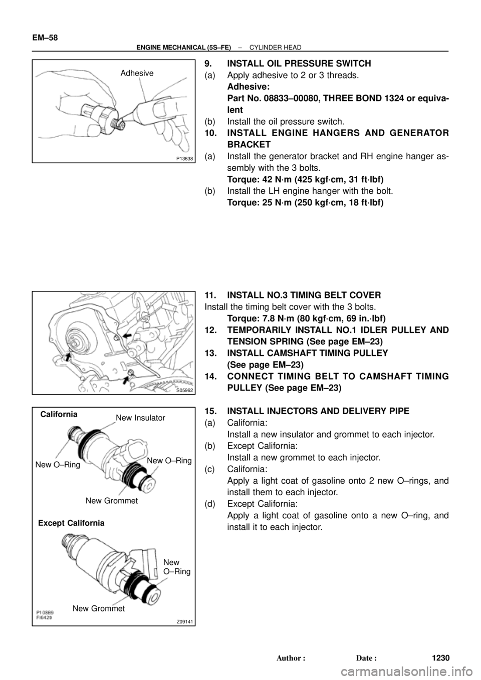
9. INSTALL OIL PRESSURE SWITCH
(a) Apply adhesive to 2 or 3 threads.
Adhesive:
Part No. 08833±00080, THREE BOND 1324 or equiva-
lent
(b) Install the oil pressure switch.
10. INSTALL ENGINE HANGERS AND GENERATOR
BRACKET
(a) Install the generator bracket and RH engine hanger as-
sembly with the 3 bolts.
Torque: 42 N´m (425 kgf´cm, 31 ft´lbf)
(b) Install the LH engine hanger with the bolt.
Torque: 25 N´m (250 kgf´cm, 18 ft´lbf)
11. INSTALL NO.3 TIMING BELT COVER
Install the timing belt cover with the 3 bolts.
Torque: 7.8 N´m (80 kgf´cm, 69 in.´lbf)
12. TEMPORARILY INSTALL NO.1 IDLER PULLEY AND
TENSION SPRING (See page EM±23)
13. INSTALL CAMSHAFT TIMING PULLEY
(See page EM±23)
14. CONNECT TIMING BELT TO CAMSHAFT TIMING
PULLEY (See page EM±23)
15. INSTALL INJECTORS AND DELIVERY PIPE
(a) California:
Install a new insulator and grommet to each injector.
(b) Except California:
Install a new grommet to each injector.
(c) California:
Apply a light coat of gasoline onto 2 new O±rings, and
install them to each injector.
(d) Except California:
Apply a light coat of gasoline onto a new O±ring, and
install it to each injector.
Page 2618 of 4592
S05316
M/T
Engine
No.2 Exhaust
Manifold Stay
(TMMK Made)
(TMC Made)
Exhaust Pipe Bracket
Oil Pan
Insulator
No.1 Exhaust
Manifold Stay
Back±Up Light Switch ConnectorNo.2 Rear End Plate Flywheel
LH Stiffener Plate
Clutch Disk
Clutch Cover
Engine Wire
VSS Connector
Wire Clamp
Ground Strap
Transaxle No.1 Rear End PlateIntake Manifold
Stay RH Stiffener Plate
N´m (kgf´cm, ft´lbf)
� Precoated partx 8
88 (900, 65)
19 (195, 14)
64(650, 47)
64(650, 47)
64(650, 47)64(650, 47)
�
: Specified torquex 6
± ENGINE MECHANICAL (5S±FE)ENGINE UNIT
EM±67
1239 Author�: Date�:
Page 2624 of 4592
S05526
TMMK
Made
TMC
Made
A02198
S05530
S05529
Turn
± ENGINE MECHANICAL (5S±FE)ENGINE UNIT
EM±73
1245 Author�: Date�:
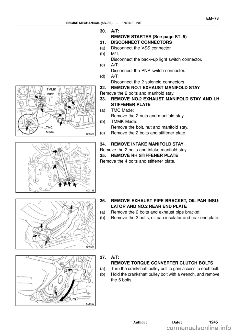
30. A/T:
REMOVE STARTER (See page ST±5)
31. DISCONNECT CONNECTORS
(a) Disconnect the VSS connector.
(b) M/T:
Disconnect the back±up light switch connector.
(c) A/T:
Disconnect the PNP switch connector.
(d) A/T:
Disconnect the 2 solenoid connectors.
32. REMOVE NO.1 EXHAUST MANIFOLD STAY
Remove the 2 bolts and manifold stay.
33. REMOVE NO.2 EXHAUST MANIFOLD STAY AND LH
STIFFENER PLATE
(a) TMC Made:
Remove the 2 nuts and manifold stay.
(b) TMMK Made:
Remove the bolt, nut and manifold stay.
(c) Remove the 2 bolts and stiffener plate.
34. REMOVE INTAKE MANIFOLD STAY
Remove the 2 bolts and intake manifold stay.
35. REMOVE RH STIFFENER PLATE
Remove the 4 bolts and stiffener plate.
36. REMOVE EXHAUST PIPE BRACKET, OIL PAN INSU-
LATOR AND NO.2 REAR END PLATE
(a) Remove the 2 bolts and exhaust pipe bracket.
(b) Remove the 2 bolts, oil pan insulator and rear end plate.
37. A/T:
REMOVE TORQUE CONVERTER CLUTCH BOLTS
(a) Turn the crankshaft pulley bolt to gain access to each bolt.
(b) Hold the crankshaft pulley bolt with a wrench, and remove
the 6 bolts.
Page 2628 of 4592

± ENGINE MECHANICAL (5S±FE)ENGINE UNIT
EM±77
1249 Author�: Date�:
Torque:
37 N´m (380 kgf´cm, 27 ft´lbf) for M/T
42 N´m (430 kgf´cm, 31 ft´lbf) for A/T
(d) TMC Made:
Tighten the nut holding the manifold stay to the cylinder
block.
Torque: 58 N´m (591 kgf´cm, 43 ft´lbf)
(e) TMMK Made:
Tighten the bolt holding the manifold stay to the cylinder
block.
Torque: 42 N´m (425 kgf´cm, 31 ft´lbf)
(f) Tighten the nut holding the manifold stay to the exhaust
manifold.
Torque: 42 N´m (425 kgf´cm, 31 ft´lbf)
12. INSTALL NO.1 EXHAUST MANIFOLD STAY
Install the manifold stay with the 2 bolts.
Torque: 42 N´m (425 kgf´cm, 31 ft´lbf)
13. CONNECT CONNECTORS
(a) Connect the VSS connector.
(b) M/T:
Connect the back±up light switch connector.
(c) A/T:
Connect the PNP switch connector.
(d) A/T:
Connect the 2 solenoid connectors.
14. A/T:
INSTALL STARTER (See page ST±19)
15. A/T:
INSTALL THROTTLE CABLE TO THROTTLE BODY
16. INSTALL NO.2 RH ENGINE MOUNTING BRACKET TO
ENGINE
Install the mounting insulator with the 3 bolts.
Torque: 52 N´m (530 kgf´cm, 38 ft´lbf)
17. INSTALL REAR ENGINE MOUNTING INSULATOR TO
ENGINE
Install the mounting insulator with the 4 bolts.
Torque: 64 N´m (650 kgf´cm, 47 ft´lbf)
18. INSTALL FRONT ENGINE MOUNTING INSULATOR TO
ENGINE
Install the mounting insulator with the 4 bolts.
Torque: 64 N´m (650 kgf´cm, 47 ft´lbf)
Page 2639 of 4592
Z19412
No.1 Balance
Shaft Mark A
Mark B No.2 Housing
S05942
Measuring Point
for Dial Indicator
SST
S05943
Z19414
No.1 Balance
Shaft
Mark A Mark B
No.2 Housing EM±88
± ENGINE MECHANICAL (5S±FE)CYLINDER BLOCK
1260 Author�: Date�:
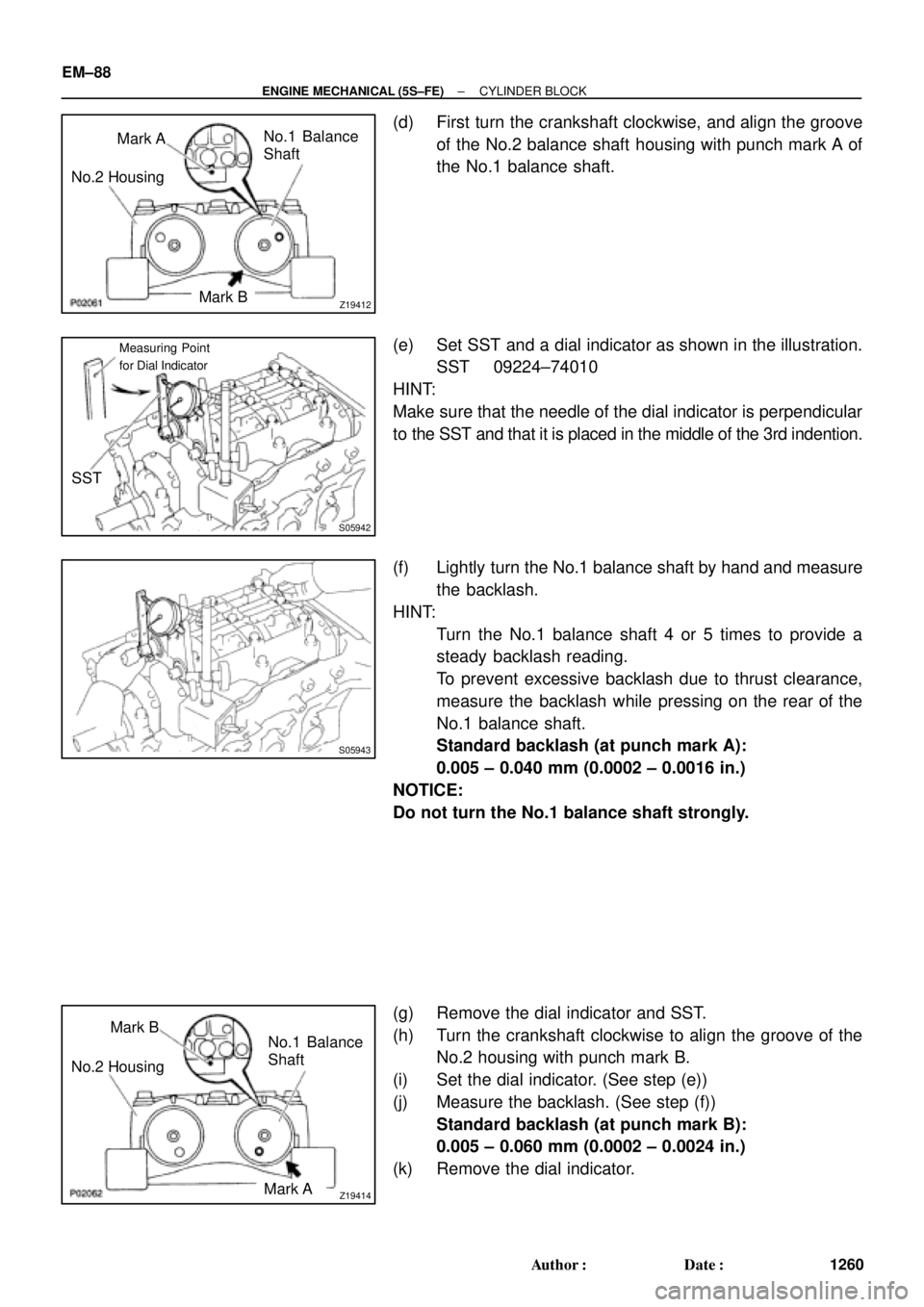
(d) First turn the crankshaft clockwise, and align the groove
of the No.2 balance shaft housing with punch mark A of
the No.1 balance shaft.
(e) Set SST and a dial indicator as shown in the illustration.
SST 09224±74010
HINT:
Make sure that the needle of the dial indicator is perpendicular
to the SST and that it is placed in the middle of the 3rd indention.
(f) Lightly turn the No.1 balance shaft by hand and measure
the backlash.
HINT:
�Turn the No.1 balance shaft 4 or 5 times to provide a
steady backlash reading.
�To prevent excessive backlash due to thrust clearance,
measure the backlash while pressing on the rear of the
No.1 balance shaft.
Standard backlash (at punch mark A):
0.005 ± 0.040 mm (0.0002 ± 0.0016 in.)
NOTICE:
Do not turn the No.1 balance shaft strongly.
(g) Remove the dial indicator and SST.
(h) Turn the crankshaft clockwise to align the groove of the
No.2 housing with punch mark B.
(i) Set the dial indicator. (See step (e))
(j) Measure the backlash. (See step (f))
Standard backlash (at punch mark B):
0.005 ± 0.060 mm (0.0002 ± 0.0024 in.)
(k) Remove the dial indicator.