Page 2719 of 4592
CYLINDER HEAD
1340 Author�: Date�:
(f) Using SST and a hammer, tap in a new guide bushing to
the specified protrusion he")
P12802
SST
Z09124
P13235
P13236
P13224
SST EM±54
± ENGINE MECHANICAL (1MZ±FE)CYLINDER HEAD
1340 Author�: Date�:
(f) Using SST and a hammer, tap in a new guide bushing to
the specified protrusion height.
SST 09201±01055, 09950±70010 (09951±07100)
Protrusion height:
Intake11.1 ± 11.3 mm (0.437 ± 0.453 in.)
Exhaust8.9 ± 9.3 mm ± (0.350 ± 0.366 in.)
(g) Using a sharp 5.5 mm reamer, ream the guide bushing to
obtain the standard specified clearance (See page
EM±43) between the guide bushing and valve stem.
2. REPLACE SPARK PLUG TUBE GASKETS
(a) Bend up the tab on the ventilation baffle plate which pre-
vents the gasket from the slipping out.
(b) Using a screwdriver and hammer, tap out the gasket.
(c) Using needle±nose pliers, pry out the gasket.
(d) Using SST and a hammer, tap in a new gasket until its sur-
face is flush with the upper edge of the cylinder head cov-
er.
SST 09608±03071
(e) Apply a light coat of MP grease to the gasket lip.
(f) Return the ventilation plate tab to its original position.
Page 2721 of 4592
Z19062
Intake ExhaustMark
TMC made
ºNOKº
TMMK made
ºFN , INº
Light Brown SurfaceGray Surface
P12668
(4)
(3)
(2)
(1)
P12476
SST
A05246
EM±56
± ENGINE MECHANICAL (1MZ±FE)CYLINDER HEAD
1342 Author�: Date�:
HINT:
The intake valve oil seal is light brown and the exhaust valve oil
seal is gray.
NOTICE:
Pay much attention when assembling the oil seal for intake
and exhaust. Assembling the wrong one may cause a fail-
ure.
(b) Install the valve (1), spring seat (2), valve spring (3) and
spring retainer (4).
(c) Using SST, compress the valve spring and place the 2
keepers around the valve stem.
SST 09202±70020 (09202±00010)
(d) Using a plastic±faced hammer and the valve stem (not in
use) tip wound with vinyl tape, lightly tap the valve stem
tip to assure proper fit.
NOTICE:
Be careful not do damage the valve stem tip.
4. INSTALL VALVE LIFTERS AND SHIMS
(a) Install the valve lifter and shim.
(b) Check that the valve lifter rotates smoothly by hand.
Page 2722 of 4592
CYLINDER HEAD
EM±57
1343 Author�: Date�:
INSTALLATION
1. PLACE C")
EM0YR±01
P12393
P12736
12 Pointed Head Bolt
Front7246
5318
7246 5318
P25742
Painted Mark
90°
Front90°
± ENGINE MECHANICAL (1MZ±FE)CYLINDER HEAD
EM±57
1343 Author�: Date�:
INSTALLATION
1. PLACE CYLINDER HEAD ON CYLINDER BLOCK
(a) Place 2 new cylinder head gaskets in position on the cylin-
der block.
NOTICE:
Be careful of the installation direction.
(b) Place the 2 cylinder heads in position on the cylinder head
gaskets.
2. INSTALL 12 POINTED HEAD CYLINDER HEAD BOLTS
HINT:
�The cylinder head bolts are tightened in 2 progressive
steps (steps (c) and (e)).
�If any bolt is broken or deformed, replace it.
(a) Apply a light coat of engine oil on the threads and under
the heads of the cylinder head bolts.
(b) Install the plate washer to the cylinder head bolt.
(c) Install and uniformly tighten the cylinder head bolts on
each cylinder head, in several passes, in the sequence
shown, then repeat for the other side, as shown.
Torque: 54 N´m (550 kgf´cm, 40 ft´lbf)
If any of the cylinder head bolts does not meet the torque speci-
fication, replace the cylinder head bolt.
(d) Mark the front of the cylinder head bolt head with paint.
(e) Retighten the cylinder head bolts by 90° in the numerical
order shown.
(f) Check that the painted mark is now at a 90° angle to the
front.
Page 2723 of 4592
P12814
Recessed Head Bolt
8 mm Hexagon Wrench
Front
P12595
Z09320
(3)
(2)
(1)
P12590
EM±58
± ENGINE MECHANICAL (1MZ±FE)CYLINDER HEAD
1344 Author�: Date�:
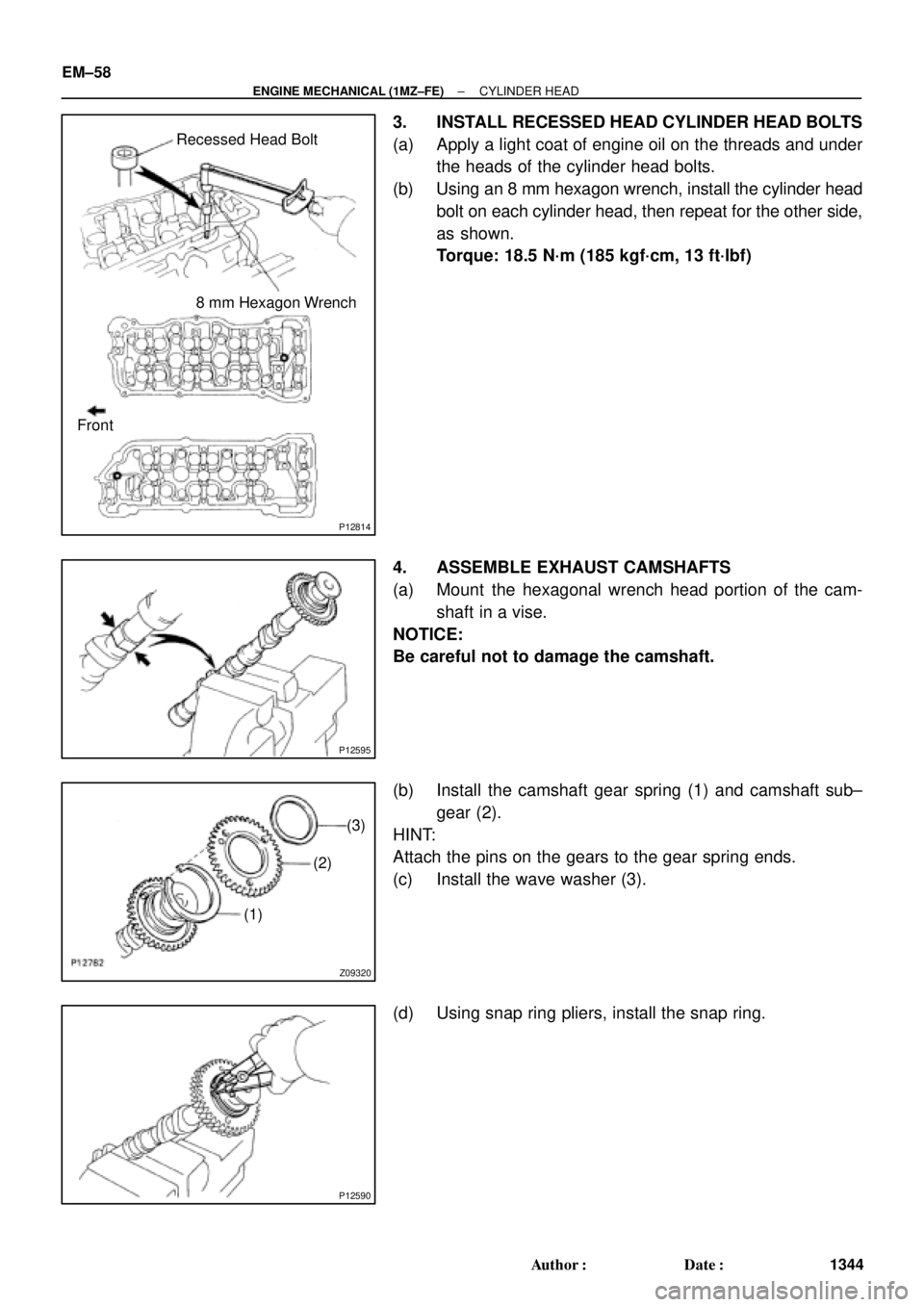
3. INSTALL RECESSED HEAD CYLINDER HEAD BOLTS
(a) Apply a light coat of engine oil on the threads and under
the heads of the cylinder head bolts.
(b) Using an 8 mm hexagon wrench, install the cylinder head
bolt on each cylinder head, then repeat for the other side,
as shown.
Torque: 18.5 N´m (185 kgf´cm, 13 ft´lbf)
4. ASSEMBLE EXHAUST CAMSHAFTS
(a) Mount the hexagonal wrench head portion of the cam-
shaft in a vise.
NOTICE:
Be careful not to damage the camshaft.
(b) Install the camshaft gear spring (1) and camshaft sub±
gear (2).
HINT:
Attach the pins on the gears to the gear spring ends.
(c) Install the wave washer (3).
(d) Using snap ring pliers, install the snap ring.
Page 2725 of 4592
CYLINDER HEAD
1346 Author�: Date�:
(b) Install th")
P12890
Exhaust
P12887
Exhaust
8
76
5
4
32
19 10
P12875
Intake
Align
P12798
Intake
P25422
Intake
8 76 5
4 32 19
10
EM±60
± ENGINE MECHANICAL (1MZ±FE)CYLINDER HEAD
1346 Author�: Date�:
(b) Install the 5 bearing caps in their proper locations.
(c) Apply a light coat of engine oil on the threads and under
the heads of the bearing cap bolts.
(d) Install and uniformly tighten the 10 bearing cap bolts, in
several passes, in the sequence shown.
Torque: 16 N´m (160 kgf´cm, 12 ft´lbf)
(e) Install the Intake camshaft.
(1) Apply new engine oil to the thrust portion and jour-
nal of the camshaft.
(2) Align the timing marks (2 dot marks) of the camshaft
drive and driven gears.
(3) Place the intake camshaft on the cylinder head.
(4) Install the 5 bearing caps in their proper locations.
(5) Apply a light coat of engine oil on the threads and
under the heads of the bearing cap bolts.
(6) Install and uniformly tighten the 10 bearing cap
bolts, in several passes, in the sequence shown.
Torque: 16 N´m (160 kgf´cm, 12 ft´lbf)
Page 2727 of 4592
CYLINDER HEAD
1348 Author�: Date�:
(7) Install t")
P12962
Exhaust
P25421
Exhaust
86 5
4 32 19
10
7
P12874
Intake
Align
P12961
Intake
P12959
Intake
6
5
4
32
19 10
7 8 EM±62
± ENGINE MECHANICAL (1MZ±FE)CYLINDER HEAD
1348 Author�: Date�:
(7) Install the 5 bearing caps in their proper locations.
(8) Apply a light coat of engine oil on the threads and
under the heads of the bearing cap bolts.
(9) Install and uniformly tighten the 10 bearing cap
bolts, in several passes, in the sequence shown.
Torque: 16 N´m (160 kgf´cm, 12 ft´lbf)
(b) Install the intake camshaft.
(1) Apply new engine oil to the thrust portion and jour-
nal of the camshaft.
(2) Align the timing marks (1 dot mark) of the camshaft
drive and driven gears.
(3) Place the intake camshaft on the cylinder head.
(4) Install the 5 bearing caps in their proper locations.
(5) Apply a light coat of engine oil on the threads and
under the heads of bearing cap bolts.
(6) Install and uniformly tighten the 10 bearing cap
bolts, in several passes, in the sequence shown.
Torque: 16 N´m (160 kgf´cm, 12 ft´lbf)
Page 2757 of 4592
P12404
P12405
P12403
P12416
60°C
P12415
EM±92
± ENGINE MECHANICAL (1MZ±FE)CYLINDER BLOCK
1378 Author�: Date�:
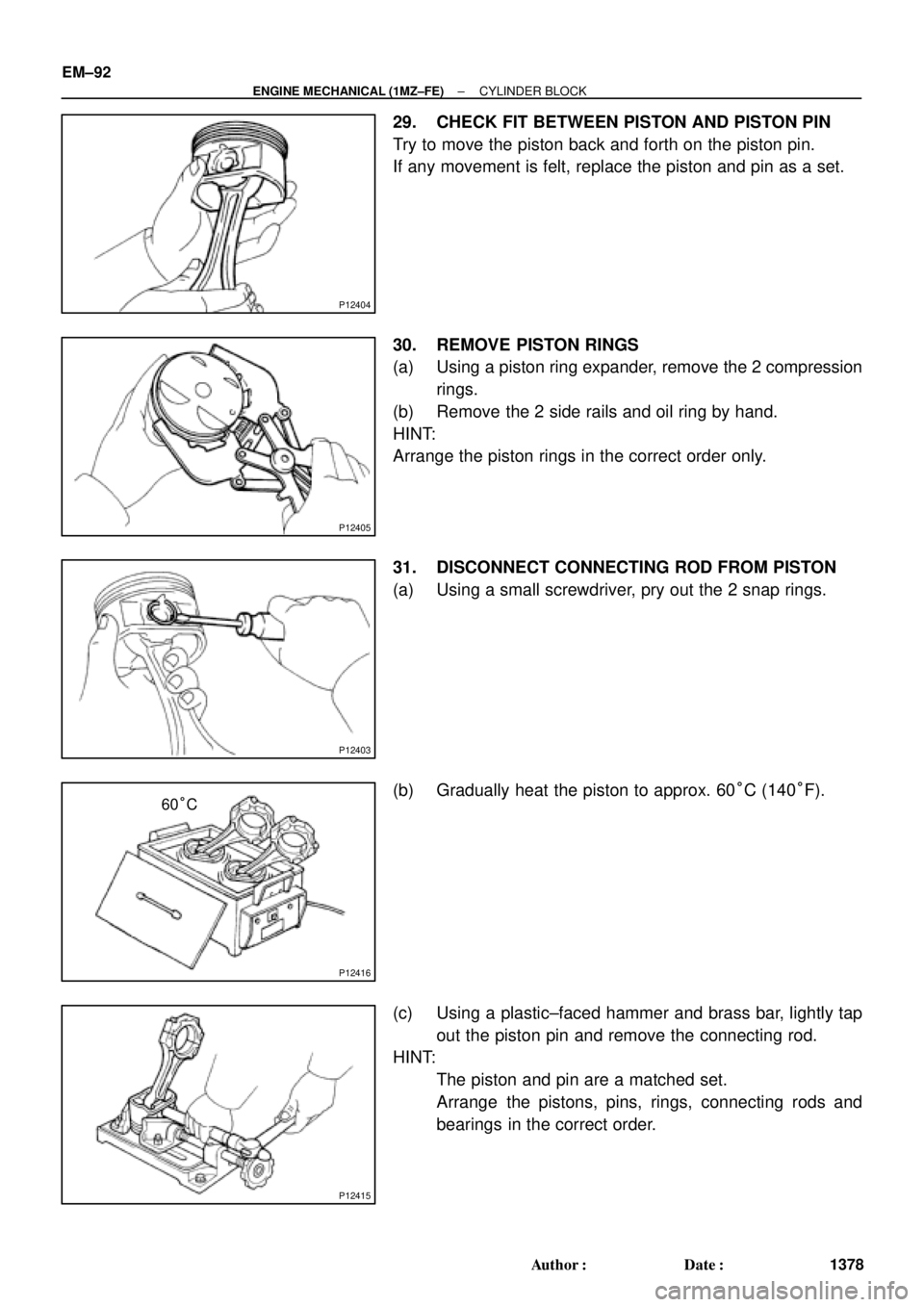
29. CHECK FIT BETWEEN PISTON AND PISTON PIN
Try to move the piston back and forth on the piston pin.
If any movement is felt, replace the piston and pin as a set.
30. REMOVE PISTON RINGS
(a) Using a piston ring expander, remove the 2 compression
rings.
(b) Remove the 2 side rails and oil ring by hand.
HINT:
Arrange the piston rings in the correct order only.
31. DISCONNECT CONNECTING ROD FROM PISTON
(a) Using a small screwdriver, pry out the 2 snap rings.
(b) Gradually heat the piston to approx. 60°C (140°F).
(c) Using a plastic±faced hammer and brass bar, lightly tap
out the piston pin and remove the connecting rod.
HINT:
�The piston and pin are a matched set.
�Arrange the pistons, pins, rings, connecting rods and
bearings in the correct order.
Page 2769 of 4592
CYLINDER BLOCK
1390 Author�: Date�:
6. PLACE CRANKSHAFT ON CYLINDER BLOCK
7. PLACE MAIN BEARING CAPS AND LOWER T")
P12495
A05264
A05265
A05266
Less than 6 mm
A05267
EM±104
± ENGINE MECHANICAL (1MZ±FE)CYLINDER BLOCK
1390 Author�: Date�:
6. PLACE CRANKSHAFT ON CYLINDER BLOCK
7. PLACE MAIN BEARING CAPS AND LOWER THRUST
WASHERS ON CYLINDER BLOCK
(a) Install the 2 thrust washers on the No.2 bearing cap with
the grooves facing outward.
(b) Temporarily place the 4 main bearing caps level and let
them in their proper locations.
(c) Apply a light coat of engine oil on the threads and under
the main bearing cap bolts for the 12 pointed head.
(d) Temporarily install the 8 main bearing cap bolts to the in-
side positions.
(e) Insert the main bearing cap with your hand until the clear-
ance between the main bearing cap and the cylinder
block will become less than 6 mm (0.23 in.) by making the
2 internal main bearing cap bolts as a guide.
(f) Using a plastic±faced hammer, lightly tap the bearing cap
to ensure a proper fit.
8. INSTALL 12 POINTED HEAD MAIN BEARING CAP
BOLTS
HINT:
�The main bearing cap bolts are tightened in 2 progressive
steps (steps (b) and (d)).
�If any of the main bearing cap bolts is broken or deformed,
replace it.

(3)
(2)
(1)
P12476
SST
A05246
EM±56
± ENGINE MECHANICAL (1MZ±FE)CYLINDER HEAD
1342 Autho")